Bosch GIS1000 Professional THERMO DETECTOR Instructions


BOSCH GIS1000 Professional THERMO DETECTOR

Safety Notes
All instructions must be read and observed in order to work safely with the measuring tool. The integrated protections in the measuring tool may be compromised if the measuring tool is not used in accordance with the instructions provided. Never make warning signs on the measuring tool unrecognisable. STORE THESE IN-STRUCTIONS IN A SAFE PLACE AND INCLUDE THEM WITH THE MEASURING TOOL WHEN GIVING IT TO A THIRD PARTY.
- Caution
The use of other operating or adjusting equipment or the application of other processing methods than those mentioned here can lead to dangerous radiation exposure. - The measuring tool is provided with a warning label (marked with number 7 in the representation of the measuring tool on the graphics page).
- Laser Radiation Class 2 do not stare into beam
- If the text of the warning label is not in your national language, stick the provided warning label in your national language over it before operating for the first time.
- Do not direct the laser beam at persons or animals and do not stare into the direct or reflected laser beam yourself, not even from a distance. You could blind somebody, cause accidents or damage your eyes.
- If laser radiation strikes your eye, you must deliberately close your eyes and immediately turn your head away from the beam.
- Do not make any modifications to the laser equipment.
- Do not use the laser viewing glasses as safety goggles. The laser viewing glasses are used for improved visualization of the laser beam, but they do not protect against laser radiation.
- Do not use the laser viewing glasses as sun glasses or in traffic. The laser viewing glasses do not afford complete UV protection and reduce colour perception
- Have the measuring tool repaired only through qualified specialists using original spare parts. This ensures that the safety of the measuring tool is maintained.
- Do not allow children to use the laser measuring tool without supervision. They could unintentionally blind other persons or themselves.
- Do not operate the measuring tool in explosive environments, such as in the presence of flammable liquids, gases or dusts. Sparks can be created in the measuring tool which may ignite the dust or fumes.
- Do not direct the light beam at persons or animals and do not stare into the light beam yourself (not even from a distance).
- Before any work on the measuring tool itself (e.g. assembling, maintenance, etc.) as well as when trans-porting and storing, remove the battery pack or the batteries from the measuring tool. Danger of injury when accidentally actuating the On/Off switch.
- Do not open the battery pack. Danger of short-circuiting.
- Protect the battery pack against heat, e.g., against continuous intense sunlight, fire, water, and moisture. Danger of explosion.
- When battery pack is not in use, keep it away from other metal objects like paper clips, coins, keys, nails, screws, or other small metal objects that can make a connection from one terminal to another. Shorting the battery terminals together may cause burns or a fire.
- Under abusive conditions, liquid may be ejected from the battery pack; avoid contact. If contact accidentally occurs, flush with water. If liquid contacts eyes, additionally seek medical help. Liquid ejected from the battery pack may cause irritations or burns
- In case of damage and improper use of the battery pack, vapours may be emitted. Provide for fresh air and seek medical help in case of complaints. The vapours can irritate the respiratory system.
- Recharge only with the charger specified by the manufacturer. A charger that is suitable for one type of battery pack may create a risk of fire when used with another
battery pack - Use the battery only in conjunction with your Bosch product. This measure alone protects the battery against dangerous overload
- Use only original Bosch battery packs with the voltage listed on the nameplate of your measuring tool. When using other battery packs, e.g. imitations, reconditioned battery packs or other brands, there is danger of injury as well as property damage through exploding battery packs.
- The battery pack can be damaged by pointed objects such as nails or screwdrivers or by force applied externally. An internal short circuit can occur and the battery pack can burn, smoke, explode or overheat.
- Caution
When using the measuring tool with Bluetooth®, interference with other devices and systems, airplanes and medical devices (e.g., cardiac pacemakers, hearing aids) may occur. Also, the possibility of humans and animals in direct vicinity being harmed cannot be completely excluded. Do not use the measuring tool with Bluetooth® in the vicinity of medical devices, petrol stations, chemical plants, areas where there is danger of explosion, and areas subject to blasting. Do not use the measuring tool with Blue-tooth® in airplanes. Avoid operation in direct vicinity of the body over longer periods.
The Bluetooth® word mark and logos are registered trade-marks owned by Bluetooth SIG, Inc. and any use of such marks by Robert Bosch GmbH is under license.
Product Description and Specifications
Please unfold the fold-out page with the representation of the measuring tool and leave it unfolded while reading the operating instructions.
Intended Use
The measuring tool is intended for contactless measurement of surface temperature, ambient temperature and relative humidity. It calculates the dew point temperature and indicates thermal bridges and mould risk. Mould spores cannot be detected with the measuring tool. It can however help with early detection of conditions in which mould spores can form. The measuring tool must not be used for temperature measurement on persons and animals or for other medical purposes. The measuring tool is not suitable for surface temperature measurement of gases. Temperature measurement of liquids is possible only with the help of a conventional thermocouple (connection type K), which can be connected to the measuring tool via the interface provided 25. The light of this measuring tool is intended to illuminate the direct work area of the measuring tool in order to take pictures. It is not suitable for household room illumination. The laser points must not be used as a laser pointer. They are used only to mark the measuring surface.
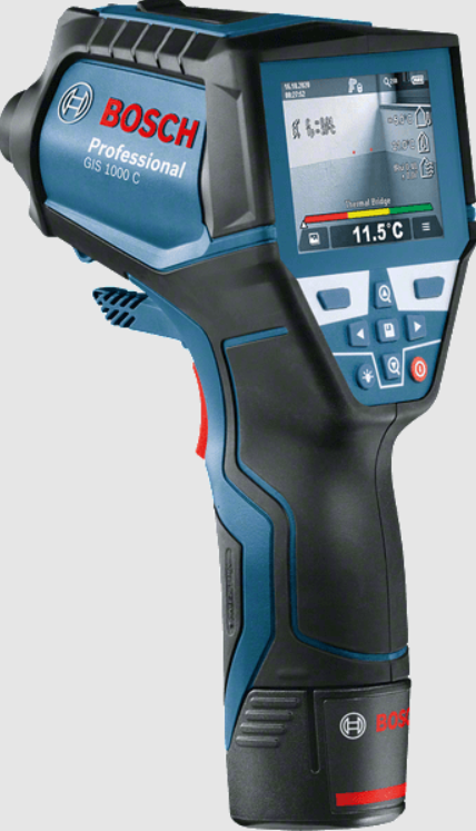
Product Features
The numbering of the product features shown refers to the illustration of the measuring tool on the graphic page.
- Cover for micro USB socket/thermocouple connection (type K)
- Exit opening for laser beam
- Unlocking button for battery pack/battery adapter/ battery lid
- Measure button/On button
- Humidity and ambient temperature sensor
- Serial number
- Laser warning label
- Micro USB cable
- Save/send by Bluetooth® button
- Right-hand function button
- Right-hand arrow button
- On/Off button
- Downward arrow button/Reduce zoom level
- Light on/off button
- Left-hand arrow button
- Upward arrow button/Increase zoom level
- Left-hand function button
- Display
- Protective cap for humidity and ambient temperature sensor
- Fixture for carrying strap
- Protective cap for infrared reception lens
- Camera
- Reception lens for infrared radiation
- Light
- Type K connection for thermocouple
- Micro USB socket
- Battery adapter cover
- Battery adapter sealing cap
- Battery port
- Battery pack*
- Battery lid
- The accessories illustrated or described are not included as standard delivery.
Technical Data

- at an ambient temperature of 20–23 °C and an emissivity degree of >0.99
- Information according to VDI/VDE 3511 Page 4.3 (publication date: July 2005); applies for 90 % of the measuring signal. Deviations of the measuring results are possible in all ranges beyond the indicated dimensions in the Technical Data.
- Refers to infrared measurement, see graphic:
- For Bluetooth® low energy devices, establishing a connection may not be possible, depending on model and operating system. Bluetooth® devices must support the SPP profile.
- limited performance at temperatures <0 °C

Technical data determined with battery from delivery scope.
The measuring tool can be clearly identified with the serial number 6 on the type plate.
Assembly
Power Supply
The measuring tool can either be operated with commercially available batteries or with a Bosch lithium-ion battery pack.
Article number 3 601 K83 370: The measuring tool can be operated only with conventional batteries.
Operation with Batteries (not for article number 3 601 K83 370)

- The non-rechargeable battery adapter is intended only for use in designated Bosch measuring tools and must not be used with power tools.
To insert the batteries, slide the cover 27 of the battery adapter into the battery port 29. Place the batteries in the cover as per the illustration on the sealing cap 28. Slide the sealing cap over the cover until you feel it engage and it is flush with the handle of the measuring tool. To remove the batteries, press the unlocking but-tons 3 of the sealing cap 28 and pull off the sealing cap. Take care that the batteries do not fall out. To do so, hold the measuring tool with the battery port 29 facing upward. Remove the batteries. To remove the inside cover 27 from the battery port 29, reach into the cover and pull it out of the measuring tool by applying light pressure to the side wall.
Always replace all batteries at the same time. Only use batter-ies from one brand and with the identical capacity. - Remove the batteries from the measuring tool when not using it for extended periods. When storing for ex-tended periods, the batteries can corrode and self-dis-charge.
Operation with Battery Pack(not for article number 3 601 K83 370)
Use of battery packs not suitable for the measuring tool can lead to malfunctions of or cause damage to the measuring tool.

- The battery pack is supplied partially charged. To ensure full capacity of the battery pack, completely charge the battery pack in the battery charger before using for the first time.
- Use only the chargers listed in the technical data. Only these battery chargers are matched to the lithium-ion battery of your measuring tool.
The lithium-ion battery pack can be charged at any time with-out reducing its service life. Interrupting the charging procedure does not damage the battery pack. - Following the automatic shut off of the measuring tool, do not continue to press the On/Off button. The battery can be damaged.
To insert the charged battery pack 30, slide it into the battery port 29 until you feel it engage and it is flush with the handle of the measuring tool. To remove the battery pack 30, press the unlocking buttons 3 and pull the battery pack out of the battery port 29. Do not exert any force.
Operation with Batteries (3 601 K83 370)

- Remove the batteries from the measuring tool when not using it for extended periods. When storing for ex-tended periods, the batteries can corrode and self-discharge.
Battery Status Indicator
The battery status indicator g on the display shows the charging state of the batteries or battery pack 30.

Operation
Initial Operation
- Keep the measuring tool dry and protect it from direct sunlight, dust and dirt.
- Do not subject the measuring tool to extreme temperatures or variations in temperature. As an example, do not leave it in vehicles for a long time. In case of large
variations in temperature, allow the measuring tool to adjust to the ambient temperature before putting it into operation. In case of extreme temperatures or variations in temperature, the accuracy of the measuring tool can be impaired. - Ensure that the measuring tool is correctly acclimatised. In case of severe variations in temperature, the aclimatisation time may be up to 15 mins.
- Avoid hard knocks to the measuring tool or dropping it. After severe external influences and in the event of abnormalities in the functionality, you should have the measuring tool checked by an authorised Bosch after-sales service agent.
- The measuring tool is equipped with a radio interface. Local operating restrictions, e.g. in airplanes or hospials, are to be observed.
Switching On and Off
Take the protective cap 21 off the infrared reception lens 23 and the protective cap 19 off the humidity and ambient temperature sensor 5. During work, ensure that the camera 22, reception lens 23 and sensor 5 are not closed off or covered, otherwise correct measurement will not be possible. To switch on the measuring tool, press the On/Off button 12 or the measure button 4. A start sequence will appear on the display 18. After the start sequence, the measuring tool will be in the operating mode that was saved the last time the tool was switched off. The lasers are not yet switched on. Only the first time the tool is started up, the “Tool” menu will additionally appear after the start sequence. In this menu you can define the settings of the measuring tool, such as the language of all indications (for operation, see ““Tool” Submenu”, page 28). Confirm the selected settings by pressing the left-hand function button 17. All settings can also be changed subsequently in the “Tool” submenu.
- Do not leave the switched-on measuring tool unattended and switch the measuring tool off after use. Other persons could be blinded by the laser beam.
- Do not point the laser beam at persons or animals and do not look into the laser beam yourself, not even from a large distance.
In the factory setting, the brightness of the display lighting is reduced 30 s after each button press to save energy. Pressing any button will switch the display lighting back to full strength. You can change this lighting time in the “Light Duration” menu (see “Light Duration”, page 29). To switch off the measuring tool, press the On/Off button. The measuring tool saves the current operating mode and the settings and then switches off. Put the protective cap 21 back on the reception lens 23 and the protective cap 19 on the humidity and ambient temperature sensor 5. Do not switch off the measuring tool by removing the battery pack or battery adapter because this may damage the internal memory in certain cases. In the “Shutdown Time” menu you can set whether and after which time interval the measuring tool will automatically switch off if no button press/measurement occurs (see “Shut-down Time”, page 29). The current operating mode and the settings are also saved when the tool switches off automatically.
If the battery or the measuring tool is not within the operating temperature range stated in the Technical Data, the measuring tool will shut down automatically after a brief warning (see “Troubleshooting – Causes and Corrective Measures”, page 29). Allow the measuring tool to reach to the correct temperature and then switch it back on. To save energy, only switch the measuring tool on when you are using it.
Setting the Zoom Level
For ongoing measurements and when rendering saved screenshots, the image detail on the display can be shown in three different zoom levels: 0.5 m, 2 m and 5 m.
The zoom levels are optimized for the corresponding distance between measuring tool and measuring object: at a measuring distance of 2 m, the zoom level “2 m” renders the (typically) best image detail. The current zoom level appears in the indicator e. Press the upward arrow button 16 to increase the zoom level, and the downward arrow button 13 to reduce it.
Illuminating the Measuring Surface
When measuring in dark areas, you can switch on the light 24 to improve the display of the screen content. This can help you to achieve a better result when saving screenshots. Press the button 14 to switch the light 24 on or off. To save energy, the light switches off automatically when the brightness of the display lighting is reduced. You can change this lighting time in the “Light Duration” menu (see “Light Duration”, page 29). The light is not automatically switched on when the display lighting is switched back on. For energy-saving reasons, the light is not available when the charging state of the battery is in the critical range.
Preparing for Measurement
Setting the Emissivity Degree for Surface-temperature Measurements
To determine the surface temperature, the natural infrared heat radiation emitted by the object is measured contact-free. For correct measurements, the emissivity degree set on the measuring tool (see “Emissivity Degree”, page 30) must be checked and if required, adapted to the object being measured prior to each measurement.
To change the set emissivity degree, open the “Main Menu” (see “Navigating the “Main Menu””, page 28).
- A selection of saved emissivity degrees is available for some of the most common materials. Select the appropriate material in the “Material” menu item. The
corresponding emissivity degree is shown in the line beneath. - If you know the exact emissivity degree of your measuring object, you can also set it as a numerical value in the “Emissivity Degree” menu item.
Inform yourself of the emissivity degree of your material. In addition to the materials stored in the measuring tool, you will find more in the table below. - Correct surface-temperature indications are only possible when the set emissivity degree and the emissivity degree of the object correspond. Correct notes on thermal bridges and the risk of mould thus also depend on the set emissivity degree.

If multiple objects made of a different material or having a different structure are measured during a measurement, the sur-face temperature indication is only binding for the objects matching the set emissivity degree.
Measuring Surface for Surface-temperature Measurements
The laser points generated by the measuring tool indicate the left-hand and right-hand boundaries of the circular measuring surface. The infrared radiation of this measuring surface is determined when performing contactless surface temperature measurement. To achieve an optimum measuring result, align the measuring tool as perpendicular as possible to the centre of the measuring surface.
- Do not point the laser beam at persons or animals and do not look into the laser beam yourself, not even from a large distance.
Increasing the distance between measuring tool and measuring object will increase the distance of the laser points and therefore the size of the measuring surface accordingly.
- Do not hold the measuring tool directly against hot sur-faces. The measuring tool can be damaged through heat.
If the laser points are difficult to see, you can switch on the Measuring Frame b on the display (see “Measuring Frame”, page 29). The measuring frame can be used as an indicator for the measuring surface and helps to improve orientation. Depending on the measuring distance, the measuring frame may deviate from the measuring surface. The area located be-tween the laser points is decisive for the measurement.
Notes on the Measuring Conditions
Highly reflective or shiny surfaces (e.g. shiny tiles or polished metals) may impair the surface temperature measurement. If necessary, mask the measuring surface with a dark, matt adhesive tape that conducts heat well. Allow the tape to acclimatise briefly on the surface. Ensure that a favourable measuring angle is used on reflective surfaces, in order to ensure that reflected heat radiation from other objects does not distort the result. For example, the re-flection of your body heat may interfere with the measurement when measuring head-on from a perpendicular position. Measuring through transparent materials (e.g. glass or trans-parent plastics) is principally not possible. The accuracy and reliability of the measuring results increase with better and more stable measuring conditions. The humidity and ambient temperature sensor 5 can be dam-aged by chemical contaminants, such as through the evaporation of paints or enamels. Infrared temperature measurement is impaired by smoke, vapour or dusty air. For this reason, ventilate indoor areas prior to measurement, especially when the air is contaminated or steamy. After ventilating, allow the room to acclimatize for a while until the usual temperature has been reached again. Ambient temperature and relative humidity are measured directly on the measuring tool using the humidity and ambient temperature sensor 5. To achieve substantial results, do not hold the measuring tool directly over or next to sources of interference such as radiators or open liquids. Do not under any circumstances cover off the sensor 5.
Measuring Functions
Standard display screen

- a Date/time: see “Time/Date”, page 28
- b Measuring frame: see “Measuring Surface for Surface-temperature Measurements”, page 24
- c Status indicator:
Measuring tool is ready to measure; press the measure button 4.


- d Audio signal switched off indicator (see “Audio Signal”, page 29)
- e Zoom level indicator: see “Setting the Zoom Level”, page 23
- f Bluetooth® switched on indicator (see “Data Transmission via Bluetooth®”, page 28)
- g Battery status indicator: see “Battery Status Indicator”, page 23
- h Function indicator/Measured value for relative humidity i Function indicator/Measured value for ambient temperature
- j Function indicator/Result for dew point temperature
- k Minimum/maximum measured value for surface temperature during a measurement
- Result scale
- m Menu symbol
- n Surface temperature alarm indicator: see “Surface Temperature Alarm”, page 26
- Measured value for surface temperature measurement
- p Current mode
- q Mark for measured value or result (depending on selected mode)
- r Gallery symbol
- s Function indicator/Measured value for average temperature
- t Function indicator/Measured value for contact temperature
- Emissivity degree indicator
- v Memory symbol
Single Measurement
Briefly press the measure button 4 once to switch on the lasers and trigger an individual measurement in the selected mode. Hold the measuring tool aimed at the measuring object without moving it until the measured value is displayed. Measurement can take up to 1 second. The lasers switch off automatically after completion of the measurement. The measuring results appear on the display. Press the measure button 4 again to start a new measurement with the set measuring parameters.
Continuous Measurement (Tracking)
Press and hold the measure button 4 to perform continuous measurements in the selected mode. The lasers remain switched on. Using slow movements, aim the laser points one after the other at all surfaces whose temperature you want to measure. Move the measuring tool slowly in the room to per-form humidity and ambient temperature measurements. The indications on the display are continually updated. As soon as you let go of the measure button 4, the measurement is interrupted and the lasers are switched off. The last measuring results are fixed on the display. Press the measure button 4 again to start a new measurement with the set measuring parameters.
Saving/Displaying/Sending Measuring Results
After completion of a measurement, the memory symbol v appears on the display to indicate that you can save the measuring results. To do so, press the save/send button 9.
The measuring results are saved as a JPG file (screenshot of the fixed display).
Surface-temperature-mode
In surface-temperature-mode, the surface temperature of an object is measured. In this mode you can, for example, search for overheated fuses or locate heating pipes or hot water pipes. To switch to surface temperature mode, return to the stand-ard display screen if not already on it. Then press the left-hand arrow button 15 or the right-hand arrow button 11 repeatedly until the “Surface Temperature” window is dis-played with a brief explanation of the mode. To hide the explanation prematurely, press the save button 9. To hide the explanation and immediately start a measurement, press the measure button 4. Press the measure button 4 and aim the measuring tool perpendicular to the centre of the measuring object. After completion of the measurement, the surface temperature of the measuring object most recently aimed at is fixed in the indicator o. When performing continuous measurements, the most recently measured surface temperature is displayed with the mark q on the result scale l. The minimum and maximum temperature values of the measurement appear in the indicator k as soon as the difference between the measured values is more than 3 °C. This enables you to tell how high the current measured value is in relation to the temperatures already measured.
Surface Temperature Alarm
The surface temperature alarm can be used in all modes. You can set a minimum and a maximum temperature. If the temperature is below the Minimum Temperature, the temperature alarm indicator n flashes blue and a warning signal sounds if the audio signal is switched on. If the temperature exceeds the Maximum Temperature, the temperature alarm indicator n flashes red and a warning signal sounds if the audio signal is switched on. To use the surface temperature alarm, open the “Main Menu” (see “Navigating the “Main Menu””, page 28).

- Select the “Functions” submenu.
- Set “Alarm min/max” to “On”.
- Set the minimum temperature under “Alarm min”.
- Set the maximum temperature under “Alarm max”. The minimum and maximum temperatures are also saved when you set the alarm to “Off”.
Contact Temperature Measurement
Contact temperature measurement enables the temperature of an object to be measured directly using a conventional type K thermocouple.
Note:
Only use type K thermocouples. Incorrect measuring results may be obtained if other types of thermocouples are connected.
Fold open the cover 1 and connect the thermocouple to the connection 25.
- Read and observe the operating instructions of the thermocouple.
- For physical reasons, measurement with a type K thermocouple is susceptible to interference from electrical and magnetic fields. A plausibility check of the display value is recommended. Sudden shutdown of the tool, caused by electrical or magnetic interference, does not impair the function of the tool. We recommend using Bosch original accessories.
As soon as a thermocouple is connected, the indicator t appears on the display. The measured value of the indicator is continually updated. To achieve a reliable result, wait until the measured value no longer changes. This can take several minutes depending on the version of thermocouple. The contact temperature can be measured in every mode in addition to the surface temperature. However, the surface temperature is always used to determine thermal bridges and mould risk. If the thermocouple is removed, the function indicator t extinguishes on the display. Close the cover 1 again after removing the thermocouple.
Thermal-bridge-mode
In thermal-bridge-mode, surface and ambient temperature are measured and compared with each other. In case of larger differences between both temperatures, a thermal-bridge warning is indicated (see “Thermal Bridge”, page 30). To switch to thermal bridge mode, return to the standard dis-play screen if not already on it. Then press the left-hand arrow button 15 or the right-hand arrow button 11 repeatedly until the “Thermal Bridge” window is displayed with a brief explanation of the mode. To hide the explanation prematurely, press the save button 9. To hide the explanation and immediately start a measurement, press the measure button 4. Press the measure button 4 and aim the measuring tool perpendicular to the centre of the measuring object. After completion of the measurement, the surface temperature of the measuring object most recently aimed at is fixed in the indicator o and the ambient temperature in the indicator i. The measuring tool automatically compares the values and shows the interpretation of the values with the mark q on the result scale l:
- Mark q in green range (temperature difference <3.5 °C): Slight temperature difference; no thermal bridges present
- Mark q in yellow range (temperature difference 3.5 °C to 6.5 °C): Temperature difference is borderline; there may possibly be a thermal bridge in the measuring area. The insulation may be inadequate at this position. Repeat the measurement if necessary at a later point in time. When doing so, pay attention to external conditions which can affect the measurement, e.g. whether the measuring surface is heated up by direct sunlight or the measuring surface is next to an open door and the fresh air temporarily lowers the temperature.
- Mark q in red range (temperature difference >6.5 °C): The surface temperature within the measuring surface deviates significantly from the ambient temperature. There is a thermal bridge in the measuring area, which is an indication of poor insulation. You can manually adjust the temperature difference from which the mark is displayed in the red range. To do so, open the “Main Menu” (see “Navigating the “Main Menu””, page 28). Select the “Functions” submenu. Set the desired temperature difference under “Thermal Bridge”. If there are thermal bridges, check the thermal insulation in this area.
Dew Point Mode
The ambient temperature and relative humidity (see “Relative Humidity”, page 30) are measured in dew point mode. The dew point temperature is calculated based on both values (see “Dew Point Temperature”, page 30). The surface temperature is also measured. The dew point temperature is compared with the surface temperature and the result is interpreted as to the risk of mould. Please note that the measuring results are always valid only for the current measuring conditions. A measurement over time is not possible. If critical measuring results are obtained, you should repeat the measurement at different times and un-der different conditions. To switch to dew point mode, return to the standard display screen if not already on it. Then press the left-hand arrow but-ton 15 or the right-hand arrow button 11 repeatedly until the “Dew Point” window is displayed with a brief explanation of the mode. To hide the explanation prematurely, press the save button 9. To hide the explanation and immediately start a measurement, press the measure button 4. Press the measure button 4 and aim the measuring tool perpendicular to the centre of the measuring object. After completion of the measurement, the surface temperature of the measuring object most recently aimed at is fixed in the indicator o, the ambient temperature in the indicator i and the relative humidity in the indicator h. The calculated dew point temperature is displayed in j. The measuring tool automatically compares the values and shows the interpretation of the values with the mark q on the result scale l:
- Mark q in green range: There is no mould risk under the cur-rent conditions.
- Mark q in yellow range: The values are borderline; pay at-tention to room temperature, thermal bridges and humidity, and repeat the measurement if necessary at a later point in time.
- Mark q in red range: There is an increased mould risk be-cause the humidity is too high or the surface temperature is close to the dew point temperature. The conspicuous value flashes in the indicator.
A mould risk warning is given when the surface temperature is 80 % of the dew point temperature. When the risk of mould is given, you should – depending on the cause – reduce the humidity through more frequent and thorough ventilation, in-crease the room temperature and eliminate thermal bridges.
Note:
The measuring tool cannot detect mould spores. It only indicates the possible formation of mould when the conditions remain the same.
User Mode
Surface temperature, ambient temperature and relative humidity are measured in user mode. The dew point temperature and the average temperature (mean value of the surface temperatures during a continuous measurement) are calculated based on these values. You can hide the following values in the display as required: average temperature, relative humidity, ambient temperature and dew point temperature. To do so, open the “Main Menu” (see “Navigating the “Main Menu””, page 28). Select the “Functions” submenu and then “User Mode”. There you can switch the indicators “Average Temp. ”, “Humidity”, “Room Temperature” and “Dew Point” on and off. For surface temperature measurements you can choose whether the minimum and maximum values k of the result scale l are adapted automatically or defined manually. To do so, go to the “User Mode” menu and then to the “Scale Range” submenu.
- Select “Auto” if you want the values k to be determined automatically as in surface temperature mode. The minimum and maximum temperature values of the measurement appear in the indicator k as soon as the difference between the measured values is more than 3 °C.
- Select “Preset” to define the values manually. Set the de-sired values in the “User Mode” menu under “Scale Lower Limit” and “Scale Upper Limit”. The manually set
minimum and maximum values appear in the indicator k. This enables you to, for example, make screenshots of different measurements comparable using the mark q.
To switch to user mode, return to the standard display screen if not already on it. Then press the left-hand arrow button 15 or the right-hand arrow button 11 repeatedly until the “User Mode” window is displayed with a brief explanation of the mode. To hide the explanation prematurely, press the save button 9. To hide the explanation and immediately start a measurement, press the measure button 4. Press the measure button 4 and aim the measuring tool perpendicular to the centre of the measuring object. The selected values are displayed after completion of the measurement.
Data Transmission
Data Transmission via USB Interface
Fold open the cover 1. Connect the micro USB socket 26 of the measuring tool to your computer or notebook using the micro USB cable provided 8. The saved JPG files can be copied, moved or deleted from the internal memory of the measuring tool. Close the cover 1 again when you remove the micro USB cable.
Note:
Connect the measuring tool via USB only to a computer or notebook. The tool may be damaged if connected to other devices.
- The battery pack of the measuring tool cannot be charged via the USB interface. To charge the battery pack, see “Operation with Battery Pack”, page 22.
Data Transmission via Bluetooth®
The measuring tool is equipped with a Bluetooth® module, which enables data transmission via radio technology to certain mobile terminals/devices with a Bluetooth® interface (e.g., smartphones, tablets). Information about system requirements for a Bluetooth® connection can be found on the Bosch website at
www.bosch-professional.com.
To switch on the Bluetooth® connection on the measuring tool, open the “Main Menu” (see “Navigating the “Main Menu””, page 28) and set “Bluetooth” to “On”. The indicator f will appear on the display. Ensure that the Bluetooth® inter-face is activated on your mobile terminal/device. Special Bosch applications (apps) are available to extend the functional range of the mobile terminal/device and for simplification of the data processing. Depending on terminal/de-vice, these can be downloaded at the respective app stores: The connection between mobile terminal/device and measuring tool is established after the Bosch application has started (if Bluetooth® modules are activated). If multiple active measuring tools are found, select the appropriate measuring tool. A connection will be established automatically if only one active measuring tool is found.
Note:
When establishing the connection between the measuring tool and the mobile terminal/device (e.g., smart-phone, tablet) the first time (pairing), the measuring tool’s PIN code may be requested. In this case, enter “0000”. When transmitting data by means of Bluetooth®, time lags may occur between mobile terminal/device and measuring tool as a result of poor reception conditions.
“Main Menu”
Navigating the “Main Menu”
Open the “Main Menu” and select the “Tool” submenu. It contains the following menu items:

- Language:
In the “Language” menu you can change the language of all indications. - Time/Date:
To change the date and time in the indicator a, open the “Time & Date” submenu. In this submenu you can also change the date and time format. To exit the “Time & Date” submenu, press either the left-hand function button 17 under the tick symbol to save the settings or the right-hand function button 10 under the cross symbol to discard the changes. - Unit:
In the “Unit” menu you can choose whether the temperature specifications are displayed in “°C” or “°F”. - Audio Signal:
In the “Audio Signals” menu you can switch the audio signal that sounds upon a surface temperature alarm on and off. - Measuring Frame:
In the “Measuring Frame” menu you can switch the measuring frame b on the display on and off. - Colour Scheme:
In the “Colour Scheme” menu you can choose the colour of the temperature values and other indications on the dis-play. The setting will also be applied to saved screenshots. - Shutdown Time:
In the “Shutdown Time” menu you can choose the time interval after which the measuring tool will automatically shut down if no button is pressed. You can also deactivate the automatic shutdown by selecting the “Never” setting. The shorter the shutdown time, the more energy you can save. - Light Duration:
In the “Light Duration” menu you can choose the time interval after which the brightness of the display lighting will reduce if no button is pressed on the measuring tool. You can also illuminate the display permanently by selecting the “Always” setting. The shorter the light duration, the more energy you can save. - Delete All Images:
In the “Delete All Images” menu you can delete all files in the internal memory at once. Press the right-hand arrow button 11 for “more …” to enter the submenu. Then press either the left-hand function button 17 under the tick symbol to delete all files, or the right-hand function button 10 under the cross symbol to cancel the operation. - Tool Information:
Open the “Tool Information” submenu for information about the measuring tool. There you will find the serial number of the measuring tool and the installed software version.
Troubleshooting – Causes and Corrective Measures
Infrared heat radiation
Infrared heat radiation is electromagnetic radiation emitted by every body. The amount of radiation depends on the temperature and the emissivity degree of the body.
Emissivity Degree
The emissivity degree of an object depends on the material and the structure of its surface. It states how much infrared heat radiation the object emits compared to an ideal heat emitter (black body, emissivity degree = 1).
Thermal Bridge
A thermal bridge is an object that undesirably transmits heat outwards or inwards, therefore differing significantly from the temperature of the rest of a wall or from the desired temperature of a wall.
As the surface temperature at thermal bridges is lower than in the rest of the room, the risk of mould increases significantly at these locations.
Relative Humidity
The relative humidity provides information on how intensive the air is saturated with water vapour. It is stated as a percent-age of the maximum amount of water vapour that the air can absorb. The maximum amount of water vapour depends on the temperature: The higher the temperature, the more amount of water vapour the air can absorb.
When the relative humidity is too high, the risk of mould in-creases. Too low humidity can lead to health impairments.
Dew Point Temperature
The dew point temperature indicates the temperature at which the water vapour in the air starts to condense. The dew point temperature depends on the relative humidity and the air temperature. When the temperature of a surface is below the dew point temperature, water begins to condense on this surface. The larger the difference of both temperatures and the higher the relative humidity, the greater the condensation. Condensate on surfaces is a major cause for the formation of mould.

Maintenance and Service
Maintenance and Cleaning
Store and transport the measuring tool only in a suitable container such as the original packaging or the protective pouch (accessory). Do not, as an example, store the measuring tool in a plastic bag, as the evaporation could damage the humidity and temperature sensor 5. Do not affix any stickers near to the sensor on the measuring tool.
Do not store the measuring tool for long periods out of a humidity range between 30 to 50 %. When the measuring tool is stored too moist or too dry, faulty measurements can occur when starting operation. Keep the measuring tool clean at all times. Wipe off debris using a moist and soft cloth. Do not use any cleaning agents or solvents.
When cleaning, fluids should not penetrate into the measuring tool. Be very careful especially when cleaning humidity and ambient temperature sensor 5, the camera 22, the reception lens 23, the light 24 and the laser beam exit openings 2: Ensure that there is no lint on the camera, the reception lens or the laser beam exit openings. Clean the camera, the reception lens and the laser beam exit openings only with cleaning agents also suitable for camera lenses. Do not attempt to re-move dirt from the sensor, camera or reception lens using pointed objects, and do not wipe over the camera and reception lens (risk of scratching). If the event of a repair, send in the measuring tool in the original packaging or in the protective pouch (accessory). If you want your measuring tool to be calibrated again, please contact a Bosch service centre (see “After-sales Service and Application Service”).
After-sales Service and Application Service
Our after-sales service responds to your questions concerning maintenance and repair of your product as well as spare parts. Exploded views and information on spare parts can al-so be found under: www.bosch-pt.com Bosch’s application service team will gladly answer questions concerning our products and their accessories. In all correspondence and spare parts orders, please always include the 10-digit article number given on the type plate of the measuring tool.
Great Britain
Robert Bosch Ltd. (B.S.C.)
P.O. Box 98
Broadwater Park
North Orbital Road
Denham
Uxbridge
UB 9 5HJ
At www.bosch-pt.co.uk you can order spare parts or arrange the collection of a product in need of servicing or repair.
Tel. Service: (0344) 7360109
E-Mail:
Ireland
Origo Ltd.
Unit 23 Magna Drive
Magna Business Park
City West
Dublin 24
Tel. Service: (01) 4666700
Fax: (01) 4666888
Australia, New Zealand and Pacific Islands
Robert Bosch Australia Pty. Ltd.
Power Tools
Locked Bag 66
Clayton South VIC 3169
Customer Contact Center
Inside Australia:
Phone: (01300) 307044
Fax: (01300) 307045
Inside New Zealand:
Phone: (0800) 543353
Fax: (0800) 428570
Outside AU and NZ:
Phone: +61 3 95415555
www.bosch.com.au
Supplier code ERAC000385
Republic of South Africa
Customer service
Hotline: (011) 6519600
Gauteng – BSC Service Centre
35 Roper Street, New Centre
Johannesburg
Tel.: (011) 4939375
Fax: (011) 4930126
E-Mail:
KZN – BSC Service Centre
Unit E, Almar Centre
143 Crompton Street
Pinetown
Tel.: (031) 7012120
Fax: (031) 7012446
E-Mail: [email protected]
Western Cape – BSC Service Centre
Democracy Way, Prosperity Park
Milnerton
Tel.: (021) 5512577
Fax: (021) 5513223
E-Mail:
Bosch Headquarters
Midrand, Gauteng
Tel.: (011) 6519600
Fax: (011) 6519880
E-Mail:
Transport
The usable lithium-ion battery packs are subject to the Dangerous Goods Legislation requirements. The user can trans-port the battery packs by road without further requirements. When being transported by third parties (e.g. via air transport or forwarding agency), special requirements on packaging and labelling must be observed. For preparation of the item being shipped, consulting an expert for hazardous material is required. Dispatch battery packs only when the housing is undamaged. Tape or mask off open contacts and pack up the battery pack in such a manner that it cannot move around in the packaging. Please also observe possibly more detailed national regulations.
Disposal
- Measuring tools, battery packs/batteries, accessories and packaging should be sorted for environmental-friendly recycling.
Do not dispose of measuring tools and batteries/rechargeable batteries into household waste!
Only for EC countries:
According to the European Guideline 2012/19/EU, measuring tools that are no longer usable, and according to the Europe-an Guideline 2006/66/EC, defective or used battery packs/batteries, must be collected separately and disposed of in an environmentally correct manner.
Batteries no longer suitable for use can be directly returned at:
Great Britain
Robert Bosch Ltd. (B.S.C.)
P.O. Box 98
Broadwater Park
North Orbital Road
Denham
Uxbridge
UB 9 5HJ
At www.bosch-pt.co.uk you can order spare parts or arrange the collection of a product in need of servicing or repair.
Tel. Service: (0344) 7360109
E-Mail: [email protected]
Battery packs/batteries:
Li-ion:
Please observe the instructions in section “Transport”, page 31.
Integrated batteries may only be removed for disposal by qualified personnel. Opening the housing shell can destroy the measuring tool.
Subject to change without notice.
Figure 1

