Bosch GSC 2.8 Professional Metal Shear Instructions


GSC 2,8 Professional


General Power Tool Safety Warnings
Save all warnings and instructions for future reference.
The term “power tool” in the warnings refers to your mains-operated (corded) power tool or battery-operated (cordless) power tool.

- Work area safety
a) Keep the work area clean and well-lit. Cluttered or dark areas invite accidents.
b) Do not operate power tools in explosive atmospheres, such as in the presence of flammable liquids, gases or dust. Power tools create sparks that may ignite dust or fumes.
c) Keep children and bystanders away while operating a power tool. Distractions can cause you to lose control. - Electrical safety
a) Power tool plugs must match the outlet. Never modify the plug in any way. Do not use any adapter plugs with earthed (grounded) power tools. Unmodified plugs and matching outlets will reduce risk of electric shock.
b) Avoid body contact with earthed or grounded surfaces, such as pipes, radiators, ranges, and refrigerators. There is an increased risk of electric shock if your body is earthed or grounded.
c) Do not expose power tools to rain or wet conditions. Water entering a power tool will increase the risk of electric shock.
d) Do not abuse the cord. Never use the cord for carrying, pulling or unplugging the power tool. Keep cord away from heat, oil, sharp edges, and moving parts. Damaged or entangled cords increase the risk of electric shock.
e) When operating a power tool outdoors, use an extension cord suitable for outdoor use. The use of a cord suitable for outdoor use reduces the risk of electric shock.
f) If operating a power tool in a damp location is unavoidable, use a residual current device (RCD) protected supply. Use of an RCD reduces the risk of electric shock. - Personal safety
a) Stay alert, watch what you are doing, and use common sense when operating a power tool. Do not use a power tool while you are tired or under the influence of drugs, alcohol or medication. A moment of inattention while operating power tools may result in serious personal injury.
b) Use personal protective equipment. Always wear eye protection. Protective equipment such as dust masks, non-skid safety shoes, hard hat, or hearing protection used for appropriate conditions will reduce personal injuries.
c) Prevent unintentional starting. Ensure the switch is in the off-position before connecting to a power source and/or battery pack, picking up or carrying the tool. Carrying power tools with your finger on the switch or energizing power tools that have the switch on invites accidents.
d) Remove any adjusting key or wrench before turning the power tool on. A wrench or a key left attached to a rotating part of the power tool may result in personal injury.
e) Do not overreach. Keep proper footing and balance at all times. This enables better control of the power tool in unexpected situations.
f) Dress properly. Do not wear loose clothing or jewelry. Keep your hair, clothing, and gloves away from moving parts. Loose clothes, jewelry, or long hair can be caught in moving parts.
g) If devices are provided for the connection of dust extraction and collection facilities, ensure these are connected and properly used. The use of dust collection can reduce dust-related hazards. - Power tool use and care
a) Do not force the power tool. Use the correct power tool for your application. The correct power tool will do the job better and safer at the rate for which it was designed.
b) Do not use the power tool if the switch does not turn it on and off. Any power tool that cannot be controlled with the switch is dangerous and must be repaired.
c) Disconnect the plug from the power source and/or the battery pack from the power tool before making any adjustments, changing accessories, or storing power tools. Such preventive safety measures reduce the risk of starting the power tool accidentally.
d) Store idle power tools out of the reach of children and do not allow persons unfamiliar with the power tool or these instructions to operate the power tool. Power tools are dangerous in the hands of untrained users.
e) Maintain power tools. Check for misalignment or binding of moving parts, breakage of parts, and any other condition that may affect the power tool’s operation. If damaged, have the power tool repaired before use. Many accidents are caused by poorly maintained power tools.
f) Keep cutting tools sharp and clean. Properly maintained cutting tools with sharp cutting edges are less likely to bind and are easier to control.
g) Use the power tool, accessories tool bits, etc. in accordance with these instructions, taking into account the working conditions and the work to be performed. Use of the power tool for operations different from those intended could result in a hazardous situation. - Service
a) Have your power tool serviced by a qualified repair person using only identical replacement parts. This will ensure that the safety of the power tool is maintained.
Machine-specific Safety Warnings
- Secure the workpiece. A workpiece clamped with clamping devices or in a vice is held more secure than by hand.
- Always wait until the machine has come to a complete stop before placing it down. The tool insert can jam and lead to loss of control over the power tool.
- Never use a machine with a damaged cable. Do not touch the damaged cable and pull the mains plug when the cable is damaged while working. Damaged cables increase the risk of an electric shock.
Functional Description
Failure to follow the warnings and instructions may result in electric shock, fire and/or serious injury. While reading the operating instructions, unfold the graphics page for the machine and leave it open.
Intended Use
The power tool is intended for cutting sheet metals without loss due to metal chips. It is suitable for curved and straight cuts.
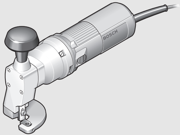
Product Features
The numbering of the product features refers to the illustration of the machine on the graphics page.

- On/Off switch
- Auxiliary handle
- Screw for auxiliary handle
- Auxiliary-handle mount
- Adjustment screw, upper cutter
- Striker
- Upper cutter
- Fastening screw for upper cutter
- Bottom cutter
- Cutting base
- Adjustment screw, bottom cutter
- Fastening screw for bottom cutter
- Setting gauge
The accessories illustrated or described are not included as standard delivery.
| Sheet Metal Shears | GSC 2,8 Professional |
| Article number | 0 601 506 1.. |
| Rated power input W | 500 |
| Output power W | 270 |
| Stroke rate at no load n0 pm | 2400 |
| Stroke speed under load spm | 1500 |
| Max. steel sheet cutting capacity* mm | 2.8 |
| Weight according to EPTA-Procedure 01/2003 kg |
2.7 |
| Protection class | /II |
Protection class
* to 400 N/mm2 with reference to steel sheet
The values given are valid for nominal voltages [U] of 230/240 V. For lower voltage and models for specific countries, these values can vary. Please observe the article number on the type plate of your machine. The trade names of the individual machines may vary.
Noise/Vibration Information
Measured values were determined according to EN 60745.
Typically the A-weighted sound pressure level of the product is 80 dB(A). Uncertainty K=3 dB. The noise level when working can exceed 80 dB(A).
Wear hearing protection!
Vibration total values (triax vector sum) determined according to EN 60745: Vibration emission value ah = 22 m/s2, Uncertainty K < 2 m/s2.
The vibration emission level given in this information sheet has been measured in accordance with a standardized test given in EN 60745 and may be used to compare one tool with another. It may be used for a preliminary assessment of exposure. The declared vibration emission level represents the main applications of the tool. However, if the tool is used for different applications, with different- ent accessories or poorly maintained, the vibration emission may differ. This may significantly increase the exposure level over the total working period.
An estimation of the level of exposure to vibration should also take into account the times when the tool is switched off or when it is running but not actually doing the job. This may significantly reduce the exposure level over the total working period.
Identify additional safety measures to protect the operator from the effects of vibration such as: maintaining the tool and the accessories, keeping the hands warm, organization of work patterns.
Declaration of Conformity

We declare under our sole responsibility that the product described under “Technical Data” is in conformity with the following standards or standardization documents: EN 60745 according to the provisions of the directives 2004/108/EC, 98/37/EC (until Dec. 28, 2009), 2006/42/EC (from Dec. 29, 2009, on).
Technical file at:
Robert Bosch GmbH, PT/ESC, D-70745 Leinfelden-Echterdingen
Dr. Egbert Schneider Senior Vice President Engineering
Dr. Eckerhard Strötgen Head of Product Certification
31.10.2007, Robert Bosch GmbH, Power Tools Division D-70745 Leinfelden-Echterdingen

Assembly
f Before any work on the machine itself, pull the mains plug.
Auxiliary Handle (see figure A)
Unscrew the screw 3 out of the auxiliary handle 2 until the auxiliary handle fits into the auxiliary handle mount 4. Slide the auxiliary handle 2 into the auxiliary-handle mount 4. Tighten the auxiliary handle by turning in a clockwise direction.
Operation
Starting Operation
Observe correct mains voltage! The voltage of the power source must agree with the voltage specified on the nameplate of the machine. Power tools marked with 230 V can also be operated with 220 V.
Switching On and Off
To start the machine, push the On/Off switch 1 forward so that the “I” is indicated on the switch. To switch off the machine, push the On/Off switch 1 toward the rear so that the “0” is indicated on the switch.
Working Advice
Apply the power tool to the workpiece only when switched on.

Hold the power tool inclined at an angle of 15° to the surface of the steel sheet and do not tilt it laterally.
Guide the machine evenly and with light feed in the cutting direction. Excessive feed significantly reduces the service life of the saw blade and can cause damage to the power tool.
Wear protective gloves while working and pay particular attention to the main cable. Sharp burrs develop at the cut steel sheet and can cause injuries to the operator or damage the mains cable.
When cutting curves, make sure not to tilt the power tool laterally and work with a low feed rate only.
Maximum Steel Sheet Cutting Capacity
The maximum steel sheet cutting capacity Dmax depends on the strength properties of the material to be cut.
The machine allows for the cutting of metal sheets to the following thicknesses:
| Material | Max. strength property 2[N/mm ] | max [mm] |
| Steel | 400 | 2.8 |
| 600 | 2.2 | |
| 800 | 1.9 | |
| Aluminum | 200 | 3.5 |
Adjusting Cutter Clearance a
The cutter clearance a (gap between the cutters) depends on the sheet thickness Dmax to be cut.

| max [mm] | Cutter clearance a [mm] |
| 0.2–1.4 | 0.3 |
| 1.5–2.8 | 0.5 |
For softer or more ductile materials, the clearance must be decreased; for harder or more brittle materials, increased.
Loosen the fastening screw 12 for the bottom cutter. Adjust the requested cutter clearance with the adjustment screw 11. The upper cutter 7 and the bottom cutter 9 may not touch each other. Check the clearance with the setting gauge 13. Retighten the fastening screw 12 for the bottom cutter.
Adjusting Cutter Clearance b
Retighten the fastening screw 8 for the upper cutter. Screw the adjustment screw for the upper cutter 5 in an anticlockwise direction until it faces against the upper cutter 7. For softer or more ductile materials, the clearance b must be decreased; for harder or more brittle materials, increased.

Maintenance and Service
Maintenance and Cleaning
Before any work on the machine itself, pull the mains plug.
For safe and proper working, always keep the machine and ventilation slots clean.
Replacing the Bottom Cutter (see figure B)
Unscrew the adjustment screw 11 of the bottom cutter. Fully unscrew the fastening screw 12 of the bottom cutter and remove the bottom cutter 9. Insert a new bottom cutter 9 into the recess of the cutting base 10. Fasten the bottom cutter with the fastening screw 12. Check the cutter clearance a (see “Adjusting Cutter Clearance a”, page 14).
Replacing the Upper Cutter (see figure B)
Both sides of the upper cutter 7 can be used.
Fully unscrew the fastening screw 8 of the upper cutter and remove the upper cutter 7.
Turn the upper cutter 7 as shown in the figure or place a new upper cutter against the striker 6. Fasten the upper cutter with fastening screw 8.
Check the cutter clearance b (see “Adjusting Cutter Clearance b”, page 15).
Regrinding the Cutters (see figure C)
Replace or regrind worn cutters in good time. Only sharp tools achieve good cutting capacity and make the machine last longer.
When regrinding the cutters, take care that the cutting angles are maintained.
Check the cutting angles with the setting gauge 13.
WARNING! Important instructions for connecting a new 3-pin plug to the 2-wire cable.
The wires in the cable are colored according to the following code:

Do not connect the blue or brown wire to the earth terminal of the plug.
Important: If for any reason the molded plug is removed from the cable of this power tool, it must be disposed of safely.
If the machine should fail despite the care taken in manufacturing and testing procedures, repair should be carried out by an after-sales service center for Bosch power tools.
In all correspondence and spare parts order, please always include the 10-digit article number given on the type plate of the machine.
Accessories/Spare Parts
Set of blades . . . . . . . . . . . . . . . . 2 607 010 025
Setting gauge . . . . . . . . . . . . . . . . 2 607 970 001
Allen key (size 5 mm) . . . . . . . . . 1 907 950 006
Allen key (size 2.5 mm) . . . . . . . . 1 907 950 003
After-sales service and customer assistance
Our after-sales service responds to your questions concerning maintenance and repair of your product as well as spare parts. Exploded views and information on spare parts can also be found under: www.bosch-pt.com
Our customer consultants answer your questions concerning best buy, application, and adjustment of products and accessories.
Great Britain
Robert Bosch Ltd. (B.S.C.)
P.O. Box 98
Broadwater Park
North Orbital Road
Denham
Uxbridge
UB 9 5HJ Tel. Service: +44 (0844) 736 0109
Fax: +44 (0844) 736 0146
E-Mail:
Ireland
Orio Ltd.
Unit 23 Magna Drive
Magna Business Park
City West
Dublin 24
Tel. Service: +353 (01) 4 66 67 00
Fax: +353 (01) 4 66 68 88
Australia, New Zealand and Pacific Islands
Robert Bosch Australia Pty. Ltd.
Power Tools
Locked Bag 66
Clayton South VIC 3169
Customer Contact Center
Inside Australia:
Phone: +61 (01300) 307 044
Fax: + 61 (01300) 307 045
Inside New Zealand:
Phone: +64 (0800) 543 353
Fax: +64 (0800) 428 570
Outside AU and NZ:
Phone: +61 (03) 9541 5555
www.bosch.com.au
Disposal
The machine, accessories, and packaging should be sorted for environmental-friendly recycling.
Only for EC countries:

Subject to change without notice.
1 609 929 N55
(14.11.07)
Bosch Power Tools