Bosch FR5CUEC Automotive Radar Sensor User Manual


Chassis Systems Control
User Manual ITA
Model: FR5CUEC
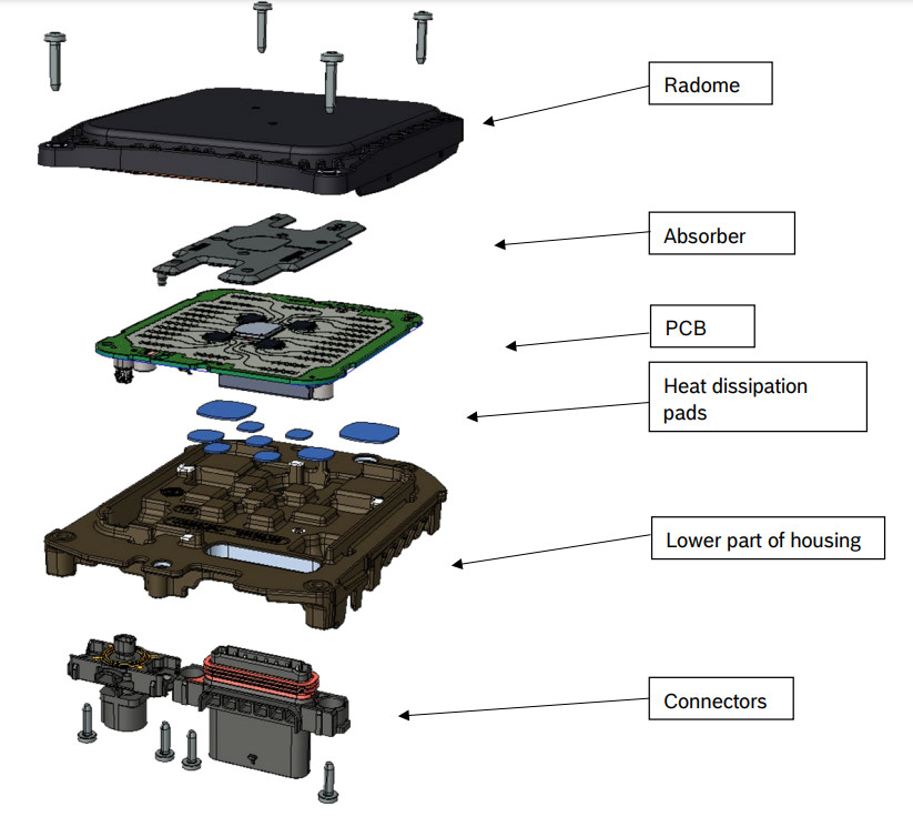
Description of FR5CUEC parts

Explanation of CW Radar function
Continuous-wave radar is a type of radar system where a known stable frequency continuous-wave radio energy is transmitted and then received from any reflecting objects. Continuous-wave (CW) radar uses Doppler, which renders the radar immune to interference from large stationary objects and slow-moving clutter.
The maximum distance in a continuous-wave radar is determined by the overall bandwidth and transmitter power. This bandwidth is determined by two factors.
- Transmit energy density (watts per Hertz)
- Receiver filter size (bandwidth divided by the total number of filters)
Frequency-modulated continuous-wave radar (FM-CW) – also called continuous-wave frequency-modulated (CWFM) radar – is a short-range measuring radar set capable of determining distance. This increases reliability by providing distance measurement along with speed measurement, which is essential when there is more than one source of reflection arriving at the radar antenna. This kind of radar is often used as a “radar altimeter” to measure the exact eight during the landing procedure of aircraft. It is also used as an early-warning radar, wave radar, and proximity sensor. Doppler shift is not always required for detection when FM is used.
In this system, the transmitted signal of a known stable frequency continuous wave varies up and down in frequency over a fixed period of time by a modulating signal. The frequency difference between the received signal and the transmit signal increases with delay, and hence with distance. This smears out or blurs, the Doppler signal. Echoes from a target are then mixed with the transmitted signal to produce a beat signal which will give the distance of the target after demodulation.
A variety of modulations is possible, the transmitter frequency can slew up and down as follows :
- Sine wave, like air raid siren
- Sawtooth wave, like the chirp from a bird
- Triangle wave, like a police siren in the United States
- Square wave, like a police siren in the United Kingdom
Range demodulation is limited to 1/4 wavelength of the transmit modulation. The instrumented range for 100 Hz FM would be 500 km. That limit depends upon the type of modulation and demodulation.
Sawtooth modulation is the most used in FM-CW radars where the range is desired for objects that lack rotating parts. Range information is mixed with the Doppler velocity using this technique. Modulation can be turned off on alternate scans to identify velocity using unmodulated carrier frequency shift. This allows range and velocity to be found with one radar set. Triangle wave modulation can be used to achieve the same goal.
As shown in the figure the received waveform (green) is simply a delayed replica of the transmitted waveform (red). The transmitted frequency is used to down-convert the received signal to the baseband, and the amount of frequency shift between the transmit signal and the reflected signal increases with time delay (distance). The time delay is thus a measure of the range; a small frequency spread is produced by nearby reflections, a larger frequency spread corresponds with more time delay and a longer range.

Ranging with an FM-CW radar system: if the error is caused by a possible Doppler frequency can be ignored and the transmitter’s power is linearly frequency modulated, then the time delay is proportional to the difference of the transmitted and the received signal at any time
References for chapter 2 of this document:
https://en.wikipedia.org/wiki/Continuous-wave_radar
This work is released under CC-BY-SA: http://creativecommons.org/licenses/by-sa/3.0/
Operating principle of the FR5CUEC
The radar sensor’s main task is to detect objects and measure their speed and position relative to the movement of the vehicle in which it is mounted.
To do this, the FR5CUEC senses the target by emitting many short frequency-modulated waves using the transmit antennas while receiving waves reflected by targets using the receive antennas.
Distance and relative speed are determined via beat frequency (due to traveling time of the waves) and phase differences between ramps (due to change of distance in a short time). By using the antenna diagram the angles of departure and arrival of the radar waves can be determined.
Using the Bosch chirp sequence radar modulation, the FR5CUEC allows unambiguous determination of relative speed in a single measurement cycle. Therefore, no complex object models are needed for ambiguity resolution.
The radar reflections (strength, distance and relative speed, angular direction, and derived values) are the basis for building a comprehensive model of the sensed environment.4 National Statements
4.1.1 Exposure information (all countries)
This device should be installed and operated with a minimum distance of 20 cm between the front of the device and the human body.
4.1.2 the United Kingdom
This device should be installed and operated with a minimum distance of 20 cm between the front of the device and the human body.
4.1.3 Canada
This device complies with Industry Canada license-exempt RSS standard(s). Operation is subject to the following two conditions:
1) this device must not cause interference, and
2) this device must accept any interference, including interference that may cause undesired operation of the device.
This equipment complies with the IC radiation exposure limits for an uncontrolled environment this equipment should be installed and operated with a minimum distance of 20 cm between the radiation source and your body.
4.1.4 the United States
This device complies with Part 15 of the FCC Rules.
Operation is subject to the following two conditions:
(1)this device may not cause harmful interference, and
(2)this device must accept any interference received, including interference that may cause undesired operation.
Changes or modifications made to this equipment not expressly approved by Robert Bosch GmbH may void the FCC authorization to operate this equipment.
This equipment has been tested and found to comply with the limits for a Class A digital device, pursuant to Part 15 of the FCC Rules. These limits are designed to provide reasonable protection against harmful interference when the equipment is operated in a commercial environment. This equipment generates, uses, and can radiate radio frequency energy and, if not installed and used in accordance with the instruction manual, may cause harmful interference to radio communications. Operation of this equipment in a residential area is likely to cause harmful interference in which case the user will be required to correct the interference at his own expense.
Radiofrequency radiation exposure Information:
This equipment complies with FCC radiation exposure limits set forth for an uncontrolled environment. This equipment should be installed and operated with a minimum distance of 20 cm between the radiator and your body.
This transmitter must not be co-located or operating in conjunction with any other antenna or transmitter.
User information
5.1 Principle
The FR5CUEC radar sensor and control unit (SCU) contains an FMCW radar transceiver operating in the globally harmonized frequency range of 76.0 – 77.0 GHz. It senses targets by emitting many short frequency-modulated waves using the transmit antennas while receiving waves reflected by targets using the receive antennas. Distance and relative speed are determined via beat frequency (due to traveling time of the waves) and phase differences between ramps (due to change of distance in a short time). By using the antenna diagram the angles of departure and arrival of the radar waves can be determined.
Using the Bosch chirp sequence radar modulation, the FR5CUEC allows unambiguous determination of relative speed in a single measurement cycle. Therefore, no complex object models are needed for ambiguity resolution.
The radar reflections (strength, distance and relative speed, angular direction, and derived values) are the basis for building a comprehensive model of the sensed environment.
5.2 Features and mechanical design
The high level of integration of the sensor and control unit functionalities, along with the compact design and space-saving planar antenna, means that the system can be easily integrated into vehicles. The FR5CUEC can be concealed in the bumper or fitted in the radiator grill of the vehicle, with minimal impact on the design or cooling airflow.
The FR5CUEC is equipped with a function for self-calibration. Once the sensor has been fitted in the vehicle, it automatically searches for reference points during the first journey and then uses these reference points to calculate the sensor axis deviation from the dynamic driving axis. The system software then compensates for this deviation. While the system is “learning” this reference information, certain functions may be deactivated or restricted. In order to achieve maximum performance on delivery, the system must be calibrated during the final stages of series production using a defined reference point. Time-consuming and expensive mechanical sensor calibration processes are not required.
Thanks to the robust sensor design, which does not have any mechanical moving parts and features a high tolerance for vibration, the FR5CUEC can be used across all vehicle segments. Radom heating is available as an option for the FR5CUEC – guaranteeing high sensor availability, even in poor weather conditions, such as snow and ice.
5.3 Areas of application
The FR5CUEC is the foundation on which a range of safety and driver assistance functions can be implemented. The FR5CUEC can be used for the following functions:
The predictive emergency braking system
With the FR5CUEC, vehicle manufacturers can meet the requirements for the automatic emergency braking systems “AEB City” and Interurban” as outlined in the Euro NCAP assessment scheme.
With its predictive emergency braking system, Bosch is helping to prevent rear-end collisions and reduce the severity of accidents. The system becomes active as soon as the vehicle is started, and supports the driver at all speeds – both day and night.
If the predictive emergency braking system determines that the distance to the preceding vehicle is becoming critical short at a vehicle speed above 5km/h, it prepares the braking system for potential emergency braking. If the driver does not react to the hazardous situation, the system warns the driver via an audible and/or visual signal, followed by a short but noticeable brake jerk.
The system then initiates partial braking to reduce the speed and give the driver valuable time to react. As soon as the driver presses the brake pedal, the system provides braking support. To do this, the system continuously calculates the degree of vehicle deceleration required to
avoid the collision. If the system detects that the driver has failed to apply sufficient brake force, it increases the braking pressure to the required level so that the driver can attempt to bring the vehicle to a standstill before a collision occurs.
If the driver fails to react to the immediate risk of collision, and the predictive emergency braking system detects that a rear-end collision is unavoidable, it can – working in conjunction with a video camera – automatically initiate full braking. As a result, the vehicle is traveling at significantly reduced speed when the collision occurs, reducing the severity of the crash for the passengers of both vehicles.
If the predictive emergency braking system detects that the distance to a moving or stationary vehicle in front is becoming critically short at a vehicle speed below 30km/h (18mph), it prepares the braking system for a potential emergency braking procedure. If the driver fails to react to the critical situation, the system can automatically initiate full braking in an attempt to prevent the collision. If the rear-end collision is unavoidable, this action can at least minimize the severity of the collision, reducing the risk of injury to the passengers of both vehicles.
Heading distance indicator
This function measures the distance from the vehicle ahead and, depending on the speed at which the vehicle is traveling, warns the driver when the safe distance from the vehicle in front is not being maintained. The function does not intervene independently but instead informs the driver of the distance from the vehicle in front via a visual and/or audible signal.
Sensor data fusion
The FR5CUEC can utilize sensor data fusion without the need for additional hardware. Sensor data fusion combines the benefits of different sensors and measuring principles in the most effective way possible, providing data that individual sensors working in isolation are unable to generate. The fusion of multiple sensors increases the measurement range, reliability, and accuracy.
Video sensors, such as the multi-purpose camera or the stereo video camera from Bosch, are the ideal supplement to radar technology. Using powerful software algorithms, the fusion of sensor data generates an extremely detailed “image”, which forms the basis for a powerful interpretation of the vehicle`s surroundings.
Sensor fusion enables the implementation of additional assistance and safety functions, such as pedestrian protection (“AEB Pedestrian”). The function for predictive pedestrian protection meets the safety requirements as specified by Euro NCAP.
It continually monitors, in combination with a video camera, the area in front of the vehicle in order to detect impending collisions with pedestrians who are in the path of the vehicle or moving toward it in a way that is likely to present a risk. If the function detects that pedestrians are at risk, it can actively trigger the application of the brakes in order to considerably reduce the risk and the consequences of the collision or to prevent the accident altogether. Sensor data fusion can also be used to significantly improve the performance of the comfort functions. Thanks to the high degree of lateral measuring accuracy of a video camera, the ACC function is able, for example, to detect vehicles merging at an earlier stage, and therefore respond in a more dynamic manner. The system also ensures that vehicles in front are assigned to the correct lanes, which further enhances ACC functionality, especially when cornering.
Vehicle Integration
This chapter describes the requirements for all parts mounted in front or around the sensor, like painted bumper, unpainted cover, and emblem/radome, regarding RF integration at 77 GHz with FR5CUEC radar sensors.
The radar sensor performance should be influenced as low as possible by the installation behind a fascia. Therefore the two-way radar loss by the fascia should be as low as possible and the reflection attenuation must fulfill the requirements listed below.
Vertical misalignment will cause additional attenuation reducing the maximum range.
Horizontal misalignment will cause reduced detection at higher azimuth angles.
Ghost target detection caused by interference signals of multiple reflections at the fascia and metallic parts of the vehicle must be avoided. A simulation can be offered to evaluate the risk and the need of using absorber material to suppress this unwanted signal. Because the threshold of detection is very low, a high attenuation is required. Plastic material can only achieve high enough attenuation if carbon black is added.
Scope of FR5CU vehicle integration
The FR5CUEC requires the installation in the front center of the vehicle. The normal vector of the sensor shall be directed in a driving direction.
6.1 Radar Cone
Radar Cone for FR5CU
The radar cone describes the zone where the fascia has to be optimized. Any parts of the vehicle inside the radar cone may influence the radar performance. Cables, brackets, bars, etc. should not touch the radar cone. The fascia in this zone may not have bends and edges as well as changes in thickness material or painting.
Based on the footprint on the top side of the radar PCB, the cone is characterized by a vertical and a horizontal opening angle. The footprint is centered on the sensor housing. A CAD model of the radar cone is available. The footprint for the radar cone has the following dimensions: (W x H) 95 mm x 84 mm
Radar cone definition for covered installation FR5CU:
The horizontal opening angle depends on the angle range that is evaluated by the sensor in azimuth and elevation.
Radar cone:
• ±75° in the horizontal direction (not including misalignment)
•±25° in the vertical direction (not including misalignment)
6.2 Fascia design guidelines
Material
Material with a low dielectric constant (εr) and low dielectric loss factor tanδ at 77 GHz should be used. Recommended are materials based on polypropylene (PP) and polymethyl methacrylate (PMMA), while materials like polycarbonate (PC) and acrylonitrile butadiene styrene (ABS) are still ok. The material shall be homogenous, compounds including glass fiber, carbon fiber, or metal particles are not recommended.
The fascia shall be designed for radar transparency. The thickness shall be a multiple of the half-wavelength (in the material) to minimize the influence of the fascia. The quality criteria of radar transparency are the reflection coefficient of the radome/fascia. Tolerances of the overall thickness and the dielectric constant of the used material influence the amount of reflection at the radome/fascia. Additional influence occurs due to curvature of the fascia. Therefore the radius has to be as large as possible. With sharp edges, the negative influence will increase significantly. Not allowed are ribs, structures, and steps changing the thickness of the radome/fascia.
Painting
The layer structure of the painting, typically made of three painting layers consisting of primer, base coating, and clear coating, will increase the effective permittivity value εr, eff, and dielectric loss factor tanδ of the painted plate used as fascia.
Fascia Classification (FR5CUEC)
The two-way radar loss caused by fascia should be as low as possible. High losses decrease the sensor performance regarding range and angle estimation. Therefore it is recommended to achieve a two-way radar loss below 3 dB.
6.3 Installation hints
To enable the full performance of the radar sensor, it is recommended to use the following installation hints and guidelines for the RF integration of the sensor.
Maximum angle between radar cone and fascia
The angle α between the radar beam inside the radar cone and the fascia may not be larger than 70° anywhere inside the radar cone.

Figure: Maximum angle between fascia and radar cone
The minimum distance between sensor and fascia
The minimum distance between the sensor radome and the fascia or any other part of the vehicle may not be smaller than 5 mm TBC.
This is valid for fascia parts fulfilling the following requirements.

Figure: Minimum distance above sensor radome
The curvature of fascia for FR5CU
The curvature of the fascia may influence radar performance, especially with low vertical tilt angles. The minimum radius of the curvature shall be according to the following rules:
Fascia thickness up to 4 mm:
R > 500 mm, no significant influence expected
R < 500 mm, significant influence possible, has to be evaluated
R < 300 mm, significant influence expected, not recommended
Fascia thickness up to 8 mm:
R > 900 mm, no significant influence expected
R < 900 mm, significant influence possible, has to be evaluated
R < 700 mm, significant influence expected, not recommended
Reflection from outside the radar cone
Reflections from structures located outside the radar cone have to be avoided. Furthermore, interference signals picked up by the sensor antennas should be avoided by keeping a minimum distance (d) of 5 mm to 10 mm for parts in front of the sensor. Even with compliance to the radar cone, reflections at parts outside the radar cone may disturb the received signal. Reflections at parts cause an interference signal to the receiving antenna and reflections at parts to get to the receiving antenna after a second reflection at the fascia (multipath reflection).
Closed surfaces of brackets and masks made of metal or high reflecting material need a tilt angle being arranged that the reflection is not received by the receiving antennas of the sensor.

Incident RF waves are reflected between components (e.g. the sensor itself, the sensor bracket, or an absorber cone) and the sensor cover. The sensor performance can deteriorate if the reflections hit the sensor. As a countermeasure, the surface tilt angles of these components and their locations have to be chosen in a way that reflections do not reach the sensor.

References for Chapter 5 of this document:
FR5CU – Technical Customer Documentation.doc
Technical Data
Frequency Band:
76 – 77 GHz
Transmit Power (EIRP pk): 37.79 dBm
Transmit Power (EIRP avg): 21.89 dBm