Bosch GTA 2500W Professional Transport and Work Bench Instruction Manual


BOSCH GTA 2500W Professional Transport and Work Bench


Safety Notes
General Safety Rules
Safety Warnings for Saw Stands
- Pull the plug from the mains receptacle and/or remove the battery from the power tool before making adjustments on the tool or changing tool accessories. Unintentional switching on of the power tool is the cause of many accidents.
- Assemble the saw stand in the proper manner before mounting the power tool. Proper assembly is important to prevent the risk of a collapse of the saw stand.
- Attach the power tool securely to the saw stand before using it. Slipping off of the power tool on the saw stand can lead to loss of control.
- Place the saw stand on a firm, level and horizontal surface. If the saw stand can slip off or wobbles, the power tool or the workpiece cannot be uniformly and securely guided.
- Do not overload the saw stand and do not use it as a ladder or scaffolding. Overloading or standing on the saw stand can lead to the upward shifting of the center of gravity of the stand and its tipping over.
- When working or transporting, take care that all bolts and connecting elements are firmly tightened. The attachment sets for the power tool must always be firmly locked. Loose connections can lead to instability and inexact sawing.
- Mount and dismount the power tool only when it is in the transport position (for instructions on the transport position, also see the operating instructions of the respective power tool). Otherwise, the power tool can have such an unfavorable center of gravity that it cannot be held securely.
- When the power tool is mounted to the attachment set, operate it exclusively on the saw stand. Without the saw stand, the attachment set with the power tool does not stand securely and can tip over.
- Ensure that long and heavy workpieces do not affect the equilibrium of the saw stand. Long and/or heavy workpieces must be sup-ported at the free end.
- Keep your fingers clear of the hinge points while pushing the saw stand together or pulling it apart. Danger of fingers being crushed or contused.
Functional Description
Read all warning notes and instructions enclosed with the saw stand and the power tool to be mounted. Failure to follow the warnings and instructions may result in electric shock, fire and/or serious injury.
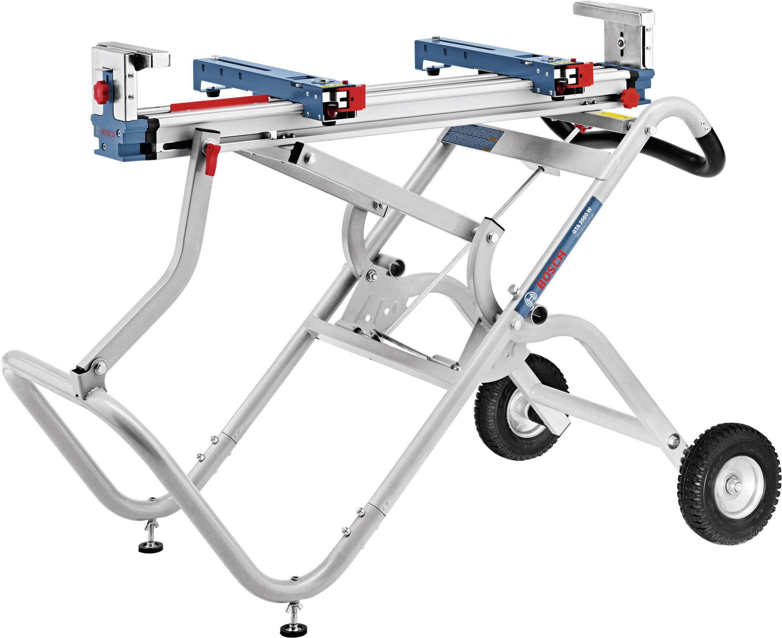
Product Features
The numbering of the product features refers to the illustration of the saw stand in the graphics.
- Attachment set
- Saw stand with support 8
- Lock for the wheels 15/16
- Locking knob of the table extension 5
- Table extension
- Handle
- Height-adjustable leg
- Support of saw stand
- Lock of support 8
- Locking knob of the workpiece support 12
- Length stop
- Workpiece support
- Upper frame with lock 3
- Foot lever
- Wheel “L”
- Wheel “R”
- Bottom frame
- Supporting frame
- Fastening kit
- Limit bolt
- Locking plate
- Wing nut
- Button for releasing lever 24
- Lever for locking the attachment set
- Stop
- Movable nut
- Nut for adjustment of lock 9
- Nut for adjustment of limit bolt 20
- Adjustment screw for limit bolt 20
*Accessories shown or described are not part of the standard delivery scope of the product. A complete overview of accessories can be found in our accessories program.
Technical Data
| Saw Stand | GTA 2500 W Professional | |
| Article number | 3 601 M12 100 | |
| Length of saw stand without table extension | mm | 1044 |
| Length of saw stand with table extension | mm |
2510 |
| Height of saw stand | mm | 947 |
| Max. carrying capacity (power tool + work- piece) – Attachment set | kg |
180 |
Max. carrying capacity (power tool + work- piece) with table extension
|
kg | 130 25 |
| Weight according to EPTA-Procedure 01/2003 | kg | 34.8 |
Assembly
Assembling the Mobile Stand Base
- Carefully remove all parts included in the delivery from their packaging.
- Remove all packaging material. (e. g. cable ties, etc.)
- For assembly, follow figures A – E. Also observe the following notes.
For Fig. B:
The wheels are marked for easier assembly (“R” for right wheel, “L” for left wheel).
Note: Do not over-tighten the nuts. Parts bolted together must move freely.
For Fig. D:
Observe the correct assembly direction of sup-porting frame 18, which is indicated by the marks “R” and “L” matching the wheels.
Note: Do not over-tighten the nuts. Parts bolted together must move freely.
For Fig. E1:
In this assembly step, the saw stand 2 is bolted together with the supporting frame rest 18 and the upper frame rest 13.
- Set both rest so that the lateral recesses in the rests face towards the handle.
- While bolting the saw stand together, take care that the support 8 is always in the fixture of the bottom frame 17.
Note: Only hand-tighten the nuts at first. After all eight bolts are correctly positioned, they can be firmly tightened.
For Fig. E2:
Note: Do not over-tighten the nuts. Parts bolted together must move freely.
Preparing the Saw Stand
Setting Up the Saw Stand
Before fastening the attachment sets and the power tool, the stand base must be pulled apart.
- To relieve the limit bolts 20, lightly pull the saw stand upward by the handle 6.
- Release lock 3.
This pulls back the limit bolts that lock the wheels in place. - Position one foot on the foot lever 14 and push the handle 6 downward with both hands until the limit bolts can engage again on the other side of the locking plates 21.
- Tighten lock 3 as well as lock 9.
The height-adjustable legs 7 are used for level-ling the saw stand.
- Loosen lock nut 22 and screw the legs in or out until the saw stand is aligned level.
Preparing the Attachment Sets
- To release the attachment set 1, press button 23 and open lever 24.
- Position the attachment set on the saw stand 2 and slide it to the red stop 25.
- Close lever 24 again. The attachment set is now firmly positioned on the saw stand.
- Measure the distance x between the mounting holes and your power tool.
- Release the second attachment set and position it at the matching clearance x to the already fastened attachment set.
- Close lever 24 again.
Fastening the Power Tool to the Attachment Sets
- Position the power tool in the transport position. Notes on the transport position are given in the operating instructions of the respective power tool.
- Position the movable nuts 26 in the attachment sets so that they match the mounting holes of the power tool.
- Screw the attachment sets and the power tool together with the respective washers and bolts.
Operation
Working Advice
Do not overload the saw stand. Always observe the maximum carrying capacity of the saw stand and the two table extensions.
Before working, always make sure that both locks 9 and 3 are closed.
Always hold the workpiece firmly, especially the longer and more heavy section. After cutting through the workpiece, the center of gravity may become dislocated in such an unfavorable manner that the saw stand tips over.
Preparing the Workpiece Support
Long workpieces must be underlaid or supported at their free end.
Adjusting the Height of the Workpiece Support
- Place your workpiece onto the saw table of the power tool.
- Loosen locking knob 10 and adjust the height of the workpiece support 12 so that the workpiece rests level.
- Retighten the locking knobs again.
Extending the Saw Stand
The saw stand can be extended on both sides.
- Place your long workpiece onto the saw table of the power tool.
- Release the respective locking knob 4 as required, and pull the table extension 5 out to the desired position.
- Retighten the locking knobs again.
Sawing Workpieces of the Same Length
The length stop 11 can be used for easily sawing workpieces to the same length.
- Pull the length stop upward to the stop and position the workpiece support at the desired clearance to the saw blade of the power tool.
Checking and Adjusting the Basic Adjustment
After intensive use, the basic settings of the saw stand must be checked and reset as required, to ensure safe and proper function.
Experience and appropriate specialty tools are required for this.
- Remove the power tool with the attachment sets.
Adjusting Lock 9
Over time, the lock 9 of support 8 can become loose.
- Close lock 9.
- Insert a slotted screwdriver between the saw stand and nut 27.
- Turn the lock in clockwise direction until the lever for locking can be firmly closed again.
- Remove the slotted screwdriver and check the adjustment again.
Adjusting the Limit Bolts of Lock 3
- Bring the saw stand into the working position (completely pulled apart).
Both limit bolts 20 must be completely extended and without a gap between limit bolts and locking plate 21.
Adjusting:
- Open nuts 28 (16 mm) a quarter turn on each side of the stand base.
- Tighten the adjustment screw 29 on the side that has a gap between limit bolt and locking plate.
If this does not reduce the gap, loosen the adjustment screw on the other side. - Repeat the procedure until both limit bolts are completely extended again and no gap is between the limit bolts and the locking plate.
- Tighten nuts 28 again.
Transport
The stand base must be folded together for transport.
- Slide the table extensions 5 all the way in as well as the workpiece supports 12 and the length stops 11 all the way down.
- Release lock 9.
- To relieve the limit bolts 20, lightly push the saw stand downward by the handle 6.
- Release lock 3.
This pulls back the limit bolts that lock the wheels in place. - Position one foot on the foot lever 14 and pull the handle 6 upward with both hands until the limit bolts can engage again on the other side of the locking plates 21.
- Close the lock 3.
Maintenance and Service
Maintenance and Cleaning
If the saw stand should fail despite the care taken in manufacture and testing, repair should be carried out by an authorized customer services agent for Bosch power tools.
In all correspondence and spare parts orders, please always include the 10-digit article number given on the type plate of the saw stand.
Wheel Inflation Pressure
The wheels are provided with an inflation pressure of 1.7-2 bar. The maximum wheel inflation pressure is 2.5 bar.
After-sales Service and Customer Assistance
Our after-sales service responds to your questions concerning maintenance and repair of your product as well as spare parts. Exploded views and information on spare parts can also be found under:
www.bosch-pt.com
Our customer consultants answer your questions concerning best buy, application and adjustment of products and accessories.
Great Britain
Robert Bosch Ltd. (B.S.C.)
P.O. Box 98
Broadwater Park
North Orbital Road
Denham
Uxbridge
UB 9 5HJ
Tel. Service: +44 (0844) 736 0109
Fax: +44 (0844) 736 0146
Email:
Ireland
Origo Ltd.
Unit 23 Magna Drive
Magna Business Park
City West
Dublin 24
Tel. Service: +353 (01) 4 66 67 00
Fax: +353 (01) 4 66 68 88
Australia, New Zealand and Pacific Islands
Robert Bosch Australia Pty. Ltd.
Power Tools
Locked Bag 66
Clayton South VIC 3169
Customer Contact Center
Inside Australia:
Phone: +61 (01300) 307 044
Fax: +61 (01300) 307 045
Inside New Zealand:
Phone: +64 (0800) 543 353
Fax: +64 (0800) 428 570
Outside AU and NZ:
Phone: +61 (03) 9541 5555
www.bosch.com.au
Disposal
The saw stand, accessories and packaging should be sorted for environmental-friendly recycling.
Subject to change without notice.