Bosch PDO Multi Metal Detector + PLL 5 Laser Instruction Manual


BOSCH PDO Multi Metal Detector + PLL 5 Laser
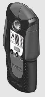

Over view


Safety Notes
- Read and observe all instructions. SAVE THESE INSTRUCTIONS FOR FUTURE REFERENCE.
- Have the measuring tool repaired only through qualified specialists using original spare parts.This ensures that the safety of the measuring tool is maintained.
- Do not operate the measuring tool in explosive environ- ments, such as in the presence of flammable liquids, gas-es or dusts. Sparks can be created in the measuring tool which may ignite the dust or fumes.
- For technological reasons, the measuring tool cannot ensure 100 % certainty. To rule out hazards, safeguard yourself each time before drilling, sawing or routing in walls, ceilings or floors by means of other information sources, such as building plans, pictures from the con-struction phase, etc. Environmental influences, such as humidity or closeness to electrical devices, can influence the accuracy of the measuring tool. Surface quality and con-dition of the walls (e.g., moisture, metallic building materi-als, conductive wallpaper, insulation materials, tiles) as well as the amount, type, size and position of the objects can lead to faulty measuring results.
Functional Description
Intended Use
The measuring tool is intended for the detection of metals (ferrous and non-ferrous metals, e.g., rebar), joists and “live” wires/conductors in walls, ceilings and floors.
Product Features
The numbering of the product features shown refers to the illustration of the measuring tool on the graphic page.
- Illuminated ring
- Marking hole
- Display
- “ZOOM” button
- Wood-detection button 6 Metal-detection button 7“on/off” button
- Felt pads
- Sensor area
- Battery lid
- Pencil for marking (removable) 12 Latch of battery lid
Display Elements
- “Live” wire indicator
- Wood detection indicator
- Metal detection indicator
- “ZOOM” function indicator
- “ZOOM” measuring indicator
- Measuring indicator
- “AutoCal” calibration indicator
- Indicator for magnetic metals
- Indicator for non-magnetic metals j Switched-off audio signal indicator k Battery low indicator
The accessories illustrated or described are not included as standard delivery.
Technical Data

Assembly
Inserting/Replacing the Battery
Using alkali-manganese or rechargeable batteries is recom-mended for operation of the measuring tool. To open the battery lid 10, press the latch 12 in the direction of the arrow and fold up the battery lid. Insert the supplied bat-tery. Pay attention that the polarity is correct, according to the representation on the inside of the battery lid. When the battery low indicator k lights up on the display, measuring is still possible for approx. 1 hour when using alkali-manganese batteries (lower battery service life for rechargea-ble batteries). When the battery low indicator k flashes, meas-uring is possible for approx. 10 minutes. When the battery low indicator k and the illuminated ring 1 (red) flash, measuring is no longer possible and the battery/rechargeable battery must be replaced.
- Remove the battery/rechargeable battery from the meas-uring tool when not using it for longer periods. When stor-ing for longer periods, the batteries/rechargeable batteries can corrode or discharge themselves.
Operation
Initial Operation
Protect the measuring tool against moisture and direct sun light.
Switching On and Off
Before switching the measuring tool on, make sure that the sensor area 9 is not moist. If required, dry the measur-ing tool using a soft cloth.
Do not subject the measuring tool to extreme tempera-tures or variations in temperature. As an example, do not leave it in vehicles for longer periods. In case of large varia-tions in temperature, allow the measuring tool to adjust to the ambient temperature before putting it into operation.
Avoid heavy impact to or falling down of the measuring tool.
To switch on switch on the measuring tool on, press any but-ton. When switching the measuring tool on with the wood-detec-tion button 5 or with the metal-detection button 6, it will auto-matically be in the respective detection function. When switching the measuring tool on with the “on/off” button 7 or with the “ZOOM” button 4, it will be in the detection func-tion last used.
After a brief self-check, the measuring tool is ready for opera-tion. When the measuring tool is in the metal-detection func-tion, the service readiness is indicated through a check mark behind the “AutoCal” calibration indicator g.
To switch the measuring tool off, press the On/Off button 7. If none of the measuring tool buttons are pressed for approx. 5 minutes, the measuring tool switches off automatically in order to extend the service life of the battery.
Before drilling, sawing or routing into a wall, protect your-self against hazards by using other information sources.
. As the measuring results can be influenced through ambient conditions or the wall material, there may be a hazard even though the indicator does not indicate an object in the sen-sor range (no audio signal or beep and and the illuminated ring 1 lit green).
Operating Modes
The measuring tool detects objects below the sensor area 9.
Detecting Metal Objects
When scanning for metal objects, press the metal-detection button 6. The metal detection indicator symbol c is indicated in the display and the illuminated ring 1 lights up green.
Position the measuring tool onto the surface to be scanned and move it sidewards. When the meas-uring tool comes close to a metal object, then the amplitude of the measuring indicator f increases; when it moves away from the object, the ampli-tude decreases. At the position of maximum amplitude, the metal object is located below the centre of the sensor (below the marking opening

As long as the measuring tool is above the metal object, the illuminated ring 1 lights up red and a steady tone sounds. To localise the object precisely, press the “ZOOM” button 4 and keep it pressed while repeatedly (3x) moving the measuring tool over the object. The “Zoom” function indicator d appears in the display. The “Zoom” measuring indicator e has the greatest amplitude over the centre of the metal object.

When very small or deeply embedded metal objects are being detected and the measuring indicator f does not react, press the “ZOOM” button 4 and keep it pressed while continuing to move the measuring tool over the area. Observe only the zoom measuring indicator e for the scan. If there are any metal inclusions in the material being scanned, then a continuous signal is indicated in the measuring indicator f. In this case, press the “ZOOM” button 4 and keep it pressed while continuing to move the measuring tool over the area. Ob-serve only the “Zoom” measuring indicator e for the scan. If the metal object found is a magnetic (e.g. iron), then the in-dicator for magnetic metals h is displayed. For non-magnetic metals, the indicator for non-magnetic metals i is displayed. In order for the measuring tool to differentiate between the metal types, it must be positioned above the detected metal object (the illuminated ring 1 lights up red). For weak signals, the in-dication of the metal type is not possible. For steel wire mesh and reinforcements in the scanned struc-tural material, an amplitude of the measuring indicator f is dis-played over the complete surface. In this case, always use the “Zoom” function for the scan. For steel wire mesh, it is typical that the indicator for magnetic metals h is displayed directly above the rebar; the indicator for non-magnetic metals i is dis-played between the rebars.
Detecting Wooden Objects
When scanning for wooden objects, press the wood-detection button 5. The wood detection indicator symbol b and the “Zoom” function indicator d are indicated in the display and the arrow below the “Zoom” function indicator d flashes. The “AutoCal” calibration indicator g and the illuminated ring 1 go out. Position the measuring tool onto the surface being scanned. Then press the “ZOOM” button 4 and keep it pressed. Now the illuminated ring 1 lights up green, the “AutoCal” calibration in-dicator g is displayed again, the “Zoom” function indicator d as well as the arrow below it go out.
With the “ZOOM” button 4 pressed, move the measuring tool uniformly above the structure without lifting it off or changing the applied pressure. During the scan, the felt pads 8 must always have contact with the structure.

When a wooden object is detected, an amplitude is displayed in the measuring indicator f. Move the measuring tool over the sur-face repeatedly to localise the wooden object more precisely. After moving over the same area several times, the wooden object can be indicated quite accurately: The illuminated ring 1 lights up red and a steady tone sounds as long as the measuring tool is over the wooden object. The measuring indicator f has the greatest amplitude over the centre of the wooden object. The “Zoom” measuring indicator e is inactive when scanning for wooden objects.
Caution: When having placed the measuring tool onto the sur-face to be scanned under which a wooden object is coinciden-tally located, and having moved it over the surface, the measur-ing indicator f, the arrow below the “Zoom” function indicator d and the illuminated ring 1 flash red. In this case, start the scan again by repositioning the measuring tool somewhat offset onto the structure and pressing the “ZOOM” button 4 again.
When scanning for wooden objects, metal objects are some-times also indicated as objects found at depths between 20–50 mm. To distinguish between wooden and metal ob-jects, switch to the detecting-metal function (see “Detecting Metal Objects”). When an object is indicated at the same loca-tion in this function, then it is clearly a metal object and not a wooden object. To continue searching for wooden objects, switch back to the detecting-wood function.
Scanning for “Live” Wires
The measuring tool indicates lines that carry a voltage between 110 V and 400 V with frequencies corresponding to the wide-spread standard (AC with 50 or 60 Hz). Other lines (DC, higher/ lower frequency or voltage) are indicated only as metal objects. “Live” wires/conductors are indicated both during a metal scan as well as during a wood scan. When a “live” wire/conductor is detected, the indicator a appears in the display. Move the meas-uring tool over the surface repeatedly in order to localise the “live” wire/conductor more precisely. After moving the measur-ing tool over the surface several times, the “live” wire/conductor can be indicated quite precisely. If the measuring tool is very close to the wire/conductor (four or five bars in indicator a), the illuminated ring 1 flashes red and the signal tone sounds with a rapid tone sequence. “Live” wires/conductors can be detected easier when power consumers (e.g., lamps, appliances) are connected to the wire/ conductor being sought and switched on. Wires/conductors with 110 V, 230 V and 400 V (three-phase current) are detected with about the same scan capacity.
Under certain conditions (such as when behind metal surfaces or behind surfaces with high water content), “live” wires/con-ductors cannot be detected with certainty. These ranges can be recognised in the metal detection function. When a measur-ing value is indicated all over a larger range of the measuring indicator f, then the material is screening off electrically and the scan for “live” wires/conductors is not reliable.
Wires that are not “live” can be found as metal objects with the detecting-metal function. However, stranded cables are not in-dicated (contrary to solid copper conductors).
Working Advice
Measuring values can be impaired through certain ambi-ent conditions. These include, e.g., the proximity of other equipment that produce strong magnetic or electromag-netic fields, moisture, metallic building materials, foil-lam-inated insulation materials or conductive wallpaper or tiles. Therefore, please also observe other information sources (e.g. construction plans) before drilling, sawing or routing into walls, ceilings or floors.
Switching Off the Signal Tone
The signal tone can be switched on and off. For this, press the metal-detection button 6 and the wood-detection button 5 at the same time. When the signal tone is switched off, the switched-off audio signal indicator j appears on the display. The signal tone setting is maintained after switching the meas-uring tool off and on again.
Marking Objects
Detected objects can be marked as required. For this, remove the pencil 11 from the measuring tool and carry out the scan as usual. Once you have found the limits or the centre of an ob-ject, simply mark the sought after location through the marking opening 2.
“AutoCal” Calibration Indicator
When the check mark behind the “AutoCal” calibration indica-tor g flashes over a longer period or if it is not displayed any-more, reliable scanning is no longer possible. In this case, send in the measuring tool to an authorised Bosch after-sales serv-ice agent. Exception: In the detecting wooden objects’ func-tion, the “AutoCal” calibration indicator g goes out as long as the “ZOOM” button 4 is not pressed.
Maintenance and Service
Maintenance and Cleaning
When the measuring indicator f continuously shows an ampli-tude even though there is no metal object in the vicinity of the measuring tool, the measuring tool can be calibrated manually. For this, remove all objects in the vicinity of the measuring tool (including wrist watches or rings of metal) and hold the meas-uring tool up in the air. With the measuring tool switched off, press both the “on/off” button 7 and the wood-detection but-ton 5 until the illuminated ring 1 lights up red and green at the same time. Then release both buttons. When the calibration process was successful, the measuring tool will start over after a few seconds and is then ready for operation.
Wipe away debris or contamination with a dry, soft cloth. Do not use cleaning agents or solvents.
In order not to affect the measuring function, decals/stickers or name plates, especially metal ones, may not be attached in the sensor area 9 on the front or back side of the measuring tool. Do not remove the felt pads 8 on the back side of the measur-ing tool. Replace the felt pads when they are damaged or used. For this, completely remove the felt pads and glue the new felt pads onto the same spots. Store and transport the measuring tool only in the supplied protective pouch. If the measuring tool should fail despite the care taken in man-ufacturing and testing procedures, repair should be carried out by an authorised after-sales service centre for Bosch power tools. Do not open the measuring tool yourself. In all correspondence and spare parts orders, please always in-clude the 10-digit article number given on the type plate of the measuring tool.
Spare Parts
Protective Pouch . . . . . . . . . . . . . . . . . . . . . . . . 1 609 203 P19
Battery lid 10 . . . . . . . . . . . . . . . . . . . . . . . . . . . 1 609 203 R32
Felt pads 8 . . . . . . . . . . . . . . . . . . . . . . . . . . . . . 1 609 203 P21
After-sales Service and Customer Assistance
Our after-sales service responds to your questions concerning maintenance and repair of your product as well as spare parts. Exploded views and information on spare parts can also be found under:
www.bosch-pt.com Our customer service representatives can answer your ques-tions concerning possible applications and adjustment of products and accessories.
Great Britain
Robert Bosch Ltd. (B.S.C.)
P.O. Box 98
Broadwater Park
North Orbital Road
Denham
Uxbridge
UB 9 5HJ
Tel. Service: +44 (0844) 736 0109
Fax: +44 (0844) 736 0146
E-Mail: [email protected]
Ireland
Origo Ltd.
Unit 23 Magna Drive
Magna Business Park
City West
Dublin 24
Tel. Service: +353 (01) 4 66 67 00
Fax: +353 (01) 4 66 68 88
Australia, New Zealand and Pacific Islands
Robert Bosch Australia Pty. Ltd.
Power Tools
Locked Bag 66
Clayton South VIC 3169
Customer Contact Center
Inside Australia:
Phone: +61 (01300) 307 044
Fax: +61 (01300) 307 045
Inside New Zealand:
Phone: +64 (0800) 543 353
Fax: +64 (0800) 428 570
Outside AU and NZ:
Phone: +61 (03) 9541 5555
www.bosch.com.au
Republic of South Africa Customer service
Hotline: +27 (011) 6 51 96 00
Gauteng – BSC Service Centre
35 Roper Street, New Centre Johannesburg
Tel.: +27 (011) 4 93 93 75
Fax: +27 (011) 4 93 01 26
E-Mail: [email protected]
KZN – BSC Service Centre
Unit E, Almar Centre
143 Crompton Street
Pinetown
Tel.: +27 (031) 7 01 21 20
Fax: +27 (031) 7 01 24 46
E-Mail: [email protected]
Western Cape – BSC Service Centre
Democracy Way, Prosperity Park Milnerton
Tel.: +27 (021) 5 51 25 77
Fax: +27 (021) 5 51 32 23
E-Mail: [email protected]
Bosch Headquarters
Midrand, Gauteng
Tel.: +27 (011) 6 51 96 00
Fax: +27 (011) 6 51 98 80
E-Mail: [email protected]
People’s Republic of China China Mainland
Bosch Power Tools (China) Co., Ltd.
567, Bin Kang Road
Bin Jiang District 310052
Hangzhou, P.R.China
Service Hotline: 400 826 8484
Fax: +86 571 8777 4502
E-Mail: [email protected]
www.bosch-pt.com.cn
HK and Macau Special Administrative Regions Robert Bosch Hong Kong Co. Ltd.
21st Floor, 625 King’s Road
North Point, Hong Kong
Customer Service Hotline: +852 (21) 02 02 35 Fax: +852 (25) 90 97 62
E-Mail: [email protected]
www.bosch-pt.com.hk
Indonesia
PT. Multi Tehaka
Kawasan Industri Pulogadung
Jalan Rawa Gelam III No. 2
Jakarta 13930
Indonesia
Tel.: +62 (21) 46 83 25 22
Fax: +62 (21) 46 82 86 45/68 23
E-Mail: [email protected]
www.multitehaka.co.id
Philippines
Robert Bosch, Inc.
28th Floor Fort Legend Towers,
3rd Avenue corner 31st Street,
Fort Bonifacio Global City,
1634 Taguig City, Philippines
Tel.: +63 (2) 870 3871
Fax: +63 (2) 870 3870
[email protected]
www.bosch-pt.com.ph
Bosch Service Center:
9725-27 Kamagong Street
San Antonio Village
Makati City, Philippines
Tel.: +63 (2) 899 9091
Fax: +63 (2) 897 6432
[email protected]
Malaysia
Robert Bosch (S.E.A.) Pte. Ltd.
No. 8A, Jalan 13/6
G.P.O. Box 10818
46200 Petaling Jaya
Selangor, Malaysia
Tel.: +60 (3) 7966 3194
Fax: +60 (3) 7958 3838
[email protected]
Toll-Free: 1800 880 188
www.bosch-pt.com.my
Thailand
Robert Bosch Ltd.
Liberty Square Building
No. 287, 11 Floor
Silom Road, Bangrak
Bangkok 10500
Tel.: +66 (2) 6 31 18 79 – 18 88 (10 lines) Fax: +66 (2) 2 38 47 83
Robert Bosch Ltd., P. O. Box 2054 Bangkok 10501, Thailand
Bosch Service – Training Centre
2869-2869/1 Soi Ban Kluay
Rama IV Road (near old Paknam Railway) Prakanong District
10110 Bangkok
Thailand
Tel.: +66 (2) 6 71 78 00 – 4
Fax: +66 (2) 2 49 42 96
Fax: +66 (2) 2 49 52 99
Singapore
Robert Bosch (SEA) Pte. Ltd.
11 Bishan Street 21
Singapore 573943
Tel.: +65 6571 2772
Fax: +65 6350 5315
[email protected]
Toll-Free: 1800 333 8333
www.bosch-pt.com.sg
Vietnam
Robert Bosch Vietnam Co. Ltd
10/F, 194 Golden Building
473 Dien Bien Phu Street
Ward 25, Binh Thanh District
84 Ho Chi Minh City
Vietnam
Tel.: +84 (8) 6258 3690 ext. 413
Fax: +84 (8) 6258 3692
[email protected]
www.bosch-pt.com
Disposal
Measuring tools, accessories and packaging should be sorted for environmental-friendly recycling. Do not dispose of measuring tools and batteries/rechargeable batteries into household waste!
Only for EC countries:
According to the European Guideline 2002/96/EC, measuring tools that are no longer usable, and ac-cording to the European Guideline 2006/66/EC, defective or used battery packs/batteries, must be collected separately and disposed of in an envi-ronmentally correct manner.
Batteries no longer suitable for use can be directly returned at:
Great Britain
Robert Bosch Ltd. (B.S.C.)
P.O. Box 98
Broadwater Park
North Orbital Road
Denham
Uxbridge
UB 9 5HJ
Tel. Service: +44 (0844) 736 0109
Fax: +44 (0844) 736 0146
E-Mail: [email protected]