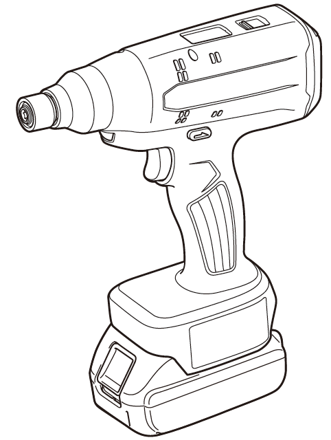
Makita DFT060T Cordless Screwdriver Instruction Manual


makita DFT060T Cordless Screwdriver

SPECIFICATIONS
| Model: | DFT060T | DFT120T | |
| Fastening torque | Hard joint | 2 – 6 N•m | 4 – 12 N•m |
| Soft joint | 2 – 6 N•m | 4 – 12 N•m | |
| No load speed (RPM) | 50 – 1,000 min-1 | 50 – 700 min-1 | |
| Operating temperature range | 0 °C – 40 °C | ||
| Dimensions (L x W x H) | with BL1815N battery | 206 mm x 75 mm x 247 mm | |
| with BL1860B battery | 206 mm x 75 mm x 263 mm | ||
| Rated voltage | D.C. 18 V | ||
| Net weight | 1.4 – 1.8 kg | ||
| Applicable USB cable | 661432-2 | ||
- Due to our continuing program of research and development, the specifications herein are subject to change without notice.
- Specifications may differ from country to country.
- The weight may differ depending on the attachment(s), including the battery cartridge. The lightest and heavi-est combination, according to EPTA-Procedure 01/2014, are shown in the table.
- Fastening torque and no load speed (RPM) can be controlled with application software designed for this tool.
Applicable battery cartridge and charger
| Battery cartridge | BL1815N / BL1820B / BL1830B / BL1840B / BL1850B / BL1860B |
| Charger | DC18RC / DC18RD / DC18RE / DC18SD / DC18SE / DC18SF / DC18SH / DC18WC |
- Some of the battery cartridges and chargers listed above may not be available depending on your region of residence.
WARNING: Only use the battery cartridges and chargers listed above. Use of any other battery cartridges and chargers may cause injury and/or fire.
Symbols
The followings show the symbols which may be used for the equipment. Be sure that you understand their meaning before use.
Read instruction manual.
Only for EU countries
Due to the presence of hazardous com-ponents in the equipment, waste electrical and electronic equipment, accumulators and batteries may have a negative impact on the environment and human health. Do not dispose of electrical and electronic appli-ances or batteries with household waste! In accordance with the European Directive on waste electrical and electronic equipment and on accumulators and batteries and waste accumulators and batteries, as well as their adaptation to national law, waste elec-trical equipment, batteries and accumulators should be stored separately and delivered to a separate collection point for municipal waste, operating in accordance with the regulations on environmental protection. This is indicated by the symbol of the crossed-out wheeled bin placed on the equipment.
Intended use
The tool is intended for screw driving in wood, metal and plastic.
Noise
The typical A-weighted noise level determined accord-ing to EN62841-2-2:
Model DFT060T
Sound pressure level (LpA) : 70 dB(A) or less Uncertainty (K) : 3 dB (A)
Model DFT120T
Sound pressure level (LpA) : 70 dB(A) or less Uncertainty (K) : 3 dB (A)
The noise level under working may exceed 80 dB (A).
NOTE: The declared noise emission value(s) has been measured in accordance with a standard test method and may be used for comparing one tool with another.
NOTE: The declared noise emission value(s) may also be used in a preliminary assessment of exposure.
WARNING: Wear ear protection.
WARNING: The noise emission during actual use of the power tool can differ from the declared value(s) depending on the ways in which the tool is used especially what kind of workpiece is processed.
WARNING: Be sure to identify safety measures to protect the operator that are based on an estima-tion of exposure in the actual conditions of use (tak-ing account of all parts of the operating cycle such as the times when the tool is switched off and when it is running idle in addition to the trigger time).
Vibration
The vibration total value (tri-axial vector sum) deter-mined according to EN62841-2-2:
Model DFT060T
Work mode: screwdriving without impact Vibration emission (ah) : 2.5 m/s2 or less Uncertainty (K) : 1.5 m/s2
Model DFT120T
Work mode: screwdriving without impact Vibration emission (ah) : 2.5 m/s2 or less Uncertainty (K) : 1.5 m/s2
NOTE: The declared vibration total value(s) has been measured in accordance with a standard test method and may be used for comparing one tool with another.
NOTE: The declared vibration total value(s) may also be used in a preliminary assessment of exposure.
WARNING: The vibration emission during actual use of the power tool can differ from the declared val-ue(s) depending on the ways in which the tool is used especially what kind of workpiece is processed.
WARNING: Be sure to identify safety measures to protect the operator that are based on an estima-tion of exposure in the actual conditions of use (tak-ing account of all parts of the operating cycle such as the times when the tool is switched off and when it is running idle in addition to the trigger time).
EC Declaration of Conformity
For European countries only The EC declaration of conformity is included as Annex A to this instruction manual.
SAFETY WARNINGS
WARNING: Read all safety warnings, instruc-tions, illustrations and specifications provided with this power tool. Failure to follow all instructions listed below may result in electric shock, fire and/or serious injury.
Save all warnings and instructions for future reference.
The term “power tool” in the warnings refers to your mains-operated (corded) power tool or battery-operated (cordless) power tool.
Work area safety
- Keep work area clean and well lit. Cluttered or dark areas invite accidents.
- Do not operate power tools in explosive atmo-spheres, such as in the presence of flammable liquids, gases or dust. Power tools create sparks which may ignite the dust or fumes.
- Keep children and bystanders away while operating a power tool. Distractions can cause you to lose control.
Electrical safety
- Power tool plugs must match the outlet. Never modify the plug in any way. Do not use any adapter plugs with earthed (grounded) power tools. Unmodified plugs and matching outlets will reduce risk of electric shock.
- Avoid body contact with earthed or grounded surfaces, such as pipes, radiators, ranges and refrigerators. There is an increased risk of elec-tric shock if your body is earthed or grounded.
- Do not expose power tools to rain or wet con-ditions. Water entering a power tool will increase the risk of electric shock.
- Do not abuse the cord. Never use the cord for carrying, pulling or unplugging the power tool. Keep cord away from heat, oil, sharp edges or moving parts. Damaged or entangled cords increase the risk of electric shock.
- When operating a power tool outdoors, use an extension cord suitable for outdoor use. Use of a cord suitable for outdoor use reduces the risk of electric shock.
- If operating a power tool in a damp location is unavoidable, use a residual current device (RCD) protected supply. Use of an RCD reduces the risk of electric shock.
- Power tools can produce electromagnetic fields (EMF) that are not harmful to the user. However, users of pacemakers and other similar medical devices should contact the maker of their device and/or doctor for advice before operating this power tool.
Personal safety
- Stay alert, watch what you are doing and use common sense when operating a power tool. Do not use a power tool while you are tired or under the influence of drugs, alcohol or med-ication. A moment of inattention while operating power tools may result in serious personal injury.
- Use personal protective equipment. Always wear eye protection. Protective equipment such as a dust mask, non-skid safety shoes, hard hat or hearing protection used for appropriate conditions will reduce personal injuries.
- Prevent unintentional starting. Ensure the switch is in the off-position before connecting to power source and/or battery pack, picking up or carrying the tool. Carrying power tools with your finger on the switch or energising power tools that have the switch on invites accidents.
- Remove any adjusting key or wrench before turning the power tool on. A wrench or a key left attached to a rotating part of the power tool may result in personal injury.
- Do not overreach. Keep proper footing and balance at all times. This enables better control of the power tool in unexpected situations.
- Dress properly. Do not wear loose clothing or jewellery. Keep your hair and clothing away from moving parts. Loose clothes, jewellery or long hair can be caught in moving parts.
- If devices are provided for the connection of dust extraction and collection facilities, ensure these are connected and properly used. Use of dust collection can reduce dust-related hazards.
- Do not let familiarity gained from frequent use of tools allow you to become complacent and ignore tool safety principles. A careless action can cause severe injury within a fraction of a second.
- Always wear protective goggles to protect your eyes from injury when using power tools. The goggles must comply with ANSI Z87.1 in the USA, EN 166 in Europe, or AS/NZS 1336 in Australia/New Zealand. In Australia/New Zealand, it is legally required to wear a face shield to protect your face, too.

Power tool use and care
- Do not force the power tool. Use the correct power tool for your application. The correct power tool will do the job better and safer at the rate for which it was designed.
- Do not use the power tool if the switch does not turn it on and off. Any power tool that cannot be controlled with the switch is dangerous and must be repaired.
- Disconnect the plug from the power source and/or remove the battery pack, if detachable, from the power tool before making any adjust-ments, changing accessories, or storing power tools. Such preventive safety measures reduce the risk of starting the power tool accidentally.
- Store idle power tools out of the reach of chil-dren and do not allow persons unfamiliar with the power tool or these instructions to operate the power tool. Power tools are dangerous in the hands of untrained users.
- Maintain power tools and accessories. Check for misalignment or binding of moving parts, break-age of parts and any other condition that may affect the power tool’s operation. If damaged, have the power tool repaired before use. Many accidents are caused by poorly maintained power tools.
- Keep cutting tools sharp and clean. Properly maintained cutting tools with sharp cutting edges are less likely to bind and are easier to control.
- Use the power tool, accessories and tool bits etc. in accordance with these instructions, tak-ing into account the working conditions and the work to be performed. Use of the power tool for operations different from those intended could result in a hazardous situation.
- Keep handles and grasping surfaces dry, clean and free from oil and grease. Slippery handles and grasping surfaces do not allow for safe handling and control of the tool in unexpected situations.
- When using the tool, do not wear cloth work gloves which may be entangled. The entangle-ment of cloth work gloves in the moving parts may result in personal injury.
Battery tool use and care
- Recharge only with the charger specified by the manufacturer. A charger that is suitable for one type of battery pack may create a risk of fire when used with another battery pack.
- Use power tools only with specifically desig-nated battery packs. Use of any other battery packs may create a risk of injury and fire.
- When battery pack is not in use, keep it away from other metal objects, like paper clips, coins, keys, nails, screws or other small metal objects, that can make a connection from one terminal to another. Shorting the battery termi-nals together may cause burns or a fire.
- Under abusive conditions, liquid may be ejected from the battery; avoid contact. If con-tact accidentally occurs, flush with water. If liquid contacts eyes, additionally seek medical help. Liquid ejected from the battery may cause irritation or burns.
- Do not use a battery pack or tool that is dam-aged or modified. Damaged or modified batteries may exhibit unpredictable behaviour resulting in fire, explosion or risk of injury.
- Do not expose a battery pack or tool to fire or excessive temperature. Exposure to fire or tem-perature above 130 °C may cause explosion.
- Follow all charging instructions and do not charge the battery pack or tool outside the temperature range specified in the instruc-tions. Charging improperly or at temperatures outside the specified range may damage the battery and increase the risk of fire.
Service
- Have your power tool serviced by a qualified repair person using only identical replacement parts. This will ensure that the safety of the power tool is maintained.
- Never service damaged battery packs. Service of battery packs should only be performed by the manufacturer or authorized service providers.
- Follow instruction for lubricating and chang-ing accessories.
Cordless screwdriver safety warnings
- Hold the power tool by insulated gripping surfaces, when performing an operation where the fastener may contact hidden wiring. Fasteners contacting a “live” wire may make exposed metal parts of the power tool “live” and could give the operator an electric shock.
- Always be sure you have a firm footing. Be sure no one is below when using the tool in high locations.
- Hold the tool firmly.
- Keep hands away from rotating parts.
- Do not touch the bit or the workpiece immedi-ately after operation; they may be extremely hot and could burn your skin.
- Always secure workpiece in a vise or similar hold-down device.
- Make sure there are no electrical cables, water pipes, gas pipes etc. that could cause a hazard if damaged by use of the tool.
SAVE THESE INSTRUCTIONS.
WARNING: DO NOT let comfort or familiarity with product (gained from repeated use) replace strict adherence to safety rules for the subject product. MISUSE or failure to follow the safety rules stated in this instruction manual may cause serious personal injury.
Important safety instructions for battery cartridge
- Before using battery cartridge, read all instruc-tions and cautionary markings on (1) battery char-ger, (2) battery, and (3) product using battery.
- Do not disassemble or tamper with the battery cartridge. It may result in a fire, excessive heat, or explosion.
- If operating time has become excessively shorter, stop operating immediately. It may result in a risk of overheating, possible burns and even an explosion.
- If electrolyte gets into your eyes, rinse them out with clear water and seek medical atten-tion right away. It may result in loss of your eyesight.
- Do not short the battery cartridge:
- Do not touch the terminals with any con-ductive material.
- Avoid storing battery cartridge in a con-tainer with other metal objects such as nails, coins, etc.
- Do not expose battery cartridge to water or rain.
- Do not store and use the tool and battery car-tridge in locations where the temperature may reach or exceed 50 °C (122 °F).
- Do not incinerate the battery cartridge even if it is severely damaged or is completely worn out. The battery cartridge can explode in a fire.
- Do not nail, cut, crush, throw, drop the battery cartridge, or hit against a hard object to the battery cartridge. Such conduct may result in a fire, excessive heat, or explosion.
- Do not use a damaged battery.
- The contained lithium-ion batteries are subject to the Dangerous Goods Legislation requirements. For commercial transports e.g. by third parties, forwarding agents, special requirement on pack-aging and labeling must be observed. For preparation of the item being shipped, consult-ing an expert for hazardous material is required. Please also observe possibly more detailed national regulations. Tape or mask off open contacts and pack up the battery in such a manner that it cannot move around in the packaging.
- When disposing the battery cartridge, remove it from the tool and dispose of it in a safe place. Follow your local regulations relating to disposal of battery.
- Use the batteries only with the products specified by Makita. Installing the batteries to non-compliant products may result in a fire, exces-sive heat, explosion, or leak of electrolyte.
- If the tool is not used for a long period of time, the battery must be removed from the tool.
- During and after use, the battery cartridge may take on heat which can cause burns or low temperature burns. Pay attention to the han-dling of hot battery cartridges.
- Do not touch the terminal of the tool imme-diately after use as it may get hot enough to cause burns.
- Do not allow chips, dust, or soil stuck into the terminals, holes, and grooves of the battery cartridge. It may cause heating, catching fire, burst and malfunction of the tool or battery car-tridge, resulting in burns or personal injury.
- Unless the tool supports the use near high-voltage electrical power lines, do not use the battery cartridge near high-voltage electri-cal power lines. It may result in a malfunction or breakdown of the tool or battery cartridge.
- Keep the battery away from children.
CAUTION: Only use genuine Makita batteries. Use of non-genuine Makita batteries, or batteries that have been altered, may result in the battery bursting causing fires, personal injury and damage. It will also void the Makita warranty for the Makita tool and charger.
Tips for maintaining maximum battery life
- Charge the battery cartridge before completely discharged. Always stop tool operation and charge the battery cartridge when you notice less tool power.
- Never recharge a fully charged battery car-tridge. Overcharging shortens the battery service life.
- Charge the battery cartridge with room tem-perature at 10 °C – 40 °C (50 °F – 104 °F). Let a hot battery cartridge cool down before charging it.
- When not using the battery cartridge, remove it from the tool or the charger.
- Charge the battery cartridge if you do not use it for a long period (more than six months).
FUNCTIONAL DESCRIPTION
CAUTION: Always be sure that the tool is switched off and the battery cartridge is removed before adjusting or checking function on the tool.
Installing or removing battery cartridge
CAUTION: Always switch off the tool before installing or removing of the battery cartridge.
CAUTION: Hold the tool and the battery car-tridge firmly when installing or removing battery cartridge. Failure to hold the tool and the battery cartridge firmly may cause them to slip off your hands and result in damage to the tool and battery cartridge and a personal injury.

- Red indicator
- Button
- Battery cartridge
To remove the battery cartridge, slide it from the tool while sliding the button on the front of the cartridge. To install the battery cartridge, align the tongue on the battery cartridge with the groove in the housing and slip it into place. Insert it all the way until it locks in place with a little click. If you can see the red indicator as shown in the figure, it is not locked completely.
CAUTION: Always install the battery cartridge fully until the red indicator cannot be seen. If not, it may accidentally fall out of the tool, causing injury to you or someone around you.
CAUTION: Do not install the battery cartridge forcibly. If the cartridge does not slide in easily, it is not being inserted correctly.
Indicating the remaining battery capacity
Only for battery cartridges with the indicator

- Indicator lamps
- Check button
Press the check button on the battery cartridge to indi-cate the remaining battery capacity. The indicator lamps light up for a few seconds.

NOTE: Depending on the conditions of use and the ambient temperature, the indication may differ slightly from the actual capacity.
NOTE: The first (far left) indicator lamp will blink when the battery protection system works.
Tool / battery protection system
The tool is equipped with a tool/battery protection sys-tem. This system automatically cuts off power to the motor to extend tool and battery life. The tool will auto-matically stop during operation if the tool or battery is placed under one of the following conditions:
Overload protection
When the tool/battery is operated in a manner that causes it to draw an abnormally high current, the tool stops automatically. In this situation, turn the tool off and stop the application that caused the tool to become overloaded. Then turn the tool on to restart.
Overheat protection
When the tool/battery is overheated, the tool stops automatically. In this situation, let the tool/battery cool before turning the tool on again.
Overdischarge protection
When the battery capacity is not enough, the tool stops automatically. In this case, remove the battery from the tool and charge the battery.
Protections against other causes
Protection system is also designed for other causes that could damage the tool and allows the tool to stop automatically. Take all the following steps to clear the causes, when the tool has been brought to a temporary halt or stop in operation.
- Turn the tool off, and then turn it on again to restart.
- Charge the battery(ies) or replace it/them with recharged battery(ies).
- Let the tool and battery(ies) cool down.
If no improvement can be found by restoring protection system, then contact your local Makita Service Center.
Switch action
WARNING: Before installing the battery car-tridge into the tool, always check to see that the switch trigger actuates properly and returns to the “OFF” position when released.
Pull the switch trigger to start the tool. Release the switch trigger to stop the tool.

- Switch trigger
NOTE: The tool automatically stops temporarily to save operation logs after finishing fastening.
Lighting up front lamp
Pull the switch trigger to light up the lamp. The lamp keeps on lighting while the switch trigger is being pulled. The lamp goes out approximately 10 seconds after releasing the switch trigger.

- lamp
NOTE: Pre-set lighting settings can be customized in application preferences. For detailed information, refer to the instruction manual supplied with the appli-cation software designed for this tool.
NOTE: Use a dry cloth to wipe the dirt off the lens of the lamp. Be careful not to scratch the lens of lamp, or it may lower the illumination.
Turning on display screen
Pull the switch trigger to turn the display screen on. The screen remains displayed while the switch trigger is being pulled. The screen goes off approximately 60 seconds after releasing the switch trigger.

NOTE: Default display settings can be customized in application preferences. For detailed information, refer to the instruction manual supplied with the appli-cation software designed for this tool.
NOTE: Use a dry cloth to wipe the dirt off the display screen. Be careful not to scratch the screen, or it may lower the illumination.
Reversing switch action
- CAUTION: Always check the direction of rotation before operation.
- CAUTION: Use the reversing switch only after the tool comes to a complete stop. Changing the direction of rotation before the tool stops may dam-age the tool.
- CAUTION: When not operating the tool, always set the reversing switch lever to the neu-tral position.
This tool has a reversing switch to change the direction of rotation. Depress the reversing switch lever from the A side for clockwise rotation or from the B side for coun-terclockwise rotation. When the reversing switch lever is in the neutral posi-tion, the switch trigger cannot be pulled.

- Reversing switch lever
Electric brake
This tool is equipped with an electric brake. If the tool consistently fails to quickly stop after the switch trigger is released, have the tool serviced at a Makita service center.
NOTE: An electric brake function can be activated or deactivated in application preferences. For detailed information, refer to the instruction manual supplied with the application software designed for this tool.
LED indicator / Beeper
The LED indicators and beeper become activated when the tool works in the following operating conditions and notify you of the tool status and performance currently delivered on the control panel.

- LED indicator A (in green, red, blue and yellow colors)
- LED indicator B (in blue color) (* Not serve as indica-tor for this model)
- Error code
- Status symbol
| Error code and status symbol on screen | Tool performance and function | Tool status | LED indicators/beeper status | Action to be taken | |
| LED indicators | Beeper | ||||
| – | Operation check for indicators and beeper | The tool starts to verify indica- tors and beeper operation soon after the battery cartridge is installed. | The LED indicator briefly lights up in green, red and blue in order, and then the front lamp lights up. |
A series of very short beeps | – |
| E00 | Accidental start prevention | The tool automatically stops to avoid unintentional start-up when the battery cartridge is installed with the switch trigger pulled. |
The LED indicator flashes in red and green alternately. | A series of short beeps | Release the switch trigger. |
| E01 | Auto-stop | The battery power becomes low and it is time to replace the battery cartridge. | The LED indicator flashes in red and green alternately. | A series of short beeps | Replace the battery with fully charged one. |
| E02 | Anti-reset of controller | The battery voltage drops abnormally for some reason, and the tool automatically stops operation. | The LED indicator flashes in red and green alternately. | A series of short beeps | Replace the battery with fully charged one. |
| E03 | Auto-stop for low remaining battery power | The battery power is almost used up, and the tool automati- cally stops operation. | The LED indicator lights up in red. | A long beep | Replace the battery with fully charged one. |
| E04 | Overload protection | The tool automatically stops to protect against a continuous overcurrent. | The LED indicator flashes in red and green alternately. | A series of short beeps | Remove the cause of overload and restart the tool. If no improvement is found, ask your local Makita Service Center for repair. |
| E05 | Overheat protection | The motor or controller gen- erates excessive heat, and the tool stops automatically to protect the tool from damage. | The LED indicator briefly flashes in red. |
A series of short beeps | Remove the battery cartridge immedi- ately and cool the tool down. |
| E06 | Motor lock | Motor lock has occurred, and the tool automatically stops the motor operation. | The LED indicator flashes in red and green alternately. | A series of short beeps | Release the switch trigger and pull it again. |
| E07 | Motor or controller failure detection | Motor or controller failure has been detected, and the tool automatically stops the motor operation. | The LED indicator flashes in red and green alternately. | A series of short beeps | Ask your local Makita Service Center for repair. |
| Error code and status symbol on screen | Tool performance and function | Tool status | LED indicators/beeper status | Action to be taken | |
| LED indicators | Beeper | ||||
| E09 | Torque sensor failure detection | The torque sensor cannot be monitored properly for a number of technical reasons including line breaks. | The LED indicator flashes in red and green alternately. | A series of short beeps | Remove the battery cartridge and cool the tool down. If the indica- tor remains lit, ask your local Makita Service Center for repair. |
| – | Auto-stop with fasten- ing completion | The tool automatically stops the motor operation after the pre- set fastening steps have been completed. | The LED indicator lights up in green for approximately one second. | – | – |
| – | Alert for insufficient | The tool raises an alert for | (1): The LED | A long | Retighten the screw. |
| fastening | incomplete fastening under the | indicator lights | beep | ||
| following operating conditions. | up in red for | ||||
| (1): The trigger switch is | approximately two | ||||
| released before the pre-set | seconds. | ||||
| fastening torque has been | (2): The LED | ||||
| achieved. | indicator flashes | ||||
| (2): The tool stops automati- | in yellow and red | ||||
| cally after classifying fastening | alternately for | ||||
| errors. | approximately two | ||||
| seconds. | |||||
| Waiting function between pre-set fastening steps | The tool is sitting idle, after one of the pre-set fastening steps has been completed, waiting to follow the next pre-set fasten- ing step. | The LED indicator lights up in green. | – | – | |
| * A status symbol ( ) flashes in the display screen. |
|||||
| – | Low-battery alert | The battery is becoming low on power, and the battery cartridge needs to be recharged or replaced with fully charged one. | The LED indicator slowly flashes in red. |
A series of long beeps | Replace the battery with fully charged one. |
| – | Error alert for heat detection of motor | The motor temperature cannot be monitored properly for a number of technical reasons including line breaks. | The LED indicator briefly flashes in red. |
A series of short beeps | Remove the battery cartridge and cool the tool down. If the indicator remains lit, ask your local Makita Service Center for repair. |
| Maintenance notice | Maintenance notice will be posted for optimum operational reliability when the accu- mulated maintenance count reaches the pre-set number. * A status symbol ( ) appears in the display screen when the accumulated mainte- nance count reaches the pre- set “Stop Count” number. |
The LED indicator flashes in yellow. |
– | Reset the mainte- nance count in the application software designed for this tool. | |
| Alert for storage disabled | Up to 1,000 fastening result data can be saved in the tool memory. The number of unread data in the memory reaches to the maximum. * A status symbol ( ) appears in the display screen when the storage capacity reaches the maximum. |
The LED indicator flashes in yellow. |
– | Load the fastening result data saved in the tool memory using the application software designed for this tool. | |
| – | Error alert for data | The tool raises an alert for | The LED indicator | – | Link the tool again |
| communication with | communication error in the | flashes in yellow. | with the application | ||
| computer | wired environment. | software designed | |||
| for the tool after | |||||
| restarting the | |||||
| application. | |||||
| – | Status indicator for data communication with computer | The tool informs that data communication has been securely established in the wired environment. | The LED indicator flashes in green. |
– | – |


TOOL SETTINGS
CAUTION: Make sure to adjust tool settings according to your applications and preferences before use.
CAUTION: Perform trial fastening, using a torque checker etc., if necessary, so as to verify if the updated settings are successfully applied.
NOTICE: Install the application software designed for this tool in your computer before connecting the tool to the computer for the first time. For detailed information, refer to the installa-tion manual supplied with the application software designed for this tool.
A series of operation settings, including fastening torque and no-load speed, can be adjusted via software screen. Archiving and sharing tool preferences through the software can enhance work performance.
Connecting with computer
NOTICE: Use the Makita genuine USB cable to connect the tool with your computer.
- Plug the USB cable into the USB port on your computer.
- Slide the USB cover open on top of the housing, and then plug the other end of the USB cable into the USB port on the tool.

- USB cover
- USB cable
- USB port
NOTE: The LED indicator on top of the rear display screen flashes in yellow after your computer rec-ognizes the tool plugged into the USB port. Launch the application software on your computer, and the LED indicator flashes in green after data communi-cation between the devices has been successfully established.
NOTE: While connected to your computer, the LED indicator on the tool remains flashing in green and no switch operation is available.
NOTE: Slide the USB cover close on top of the hous-ing each time after disconnecting the USB cable from the USB port on the tool.
Switch control on display panel and screen components
Buttons and descriptions on start screen

- LED indicator A
Lights up in green, red, blue and yellow colors. - Display screen
Displays and navigates you to the settings menu. - Up arrow button
Edit tool settings using four buttons on the panel accordingly. - Down arrow button
Edit tool settings using four buttons on the panel accordingly. - Left arrow button
Edit tool settings using four buttons on the panel accordingly. - Right arrow button
Edit tool settings using four buttons on the panel accordingly. - Information window
- Upper row: Fastening torque set in the previous operation
- Lower row: Rotation angle set in the previous operation
- Mode indicator
Displays the mode currently selected. * Only “manual mode” is available for this tool. - Data communication status indicator
Status symbols Indicate data communication status as follows:Status symbol Communication status Data communication not established * This symbol always appears on the screen during fastening operation.
USB data communication established - Job indicator
Displays the job number currently selected. Up to 8 jobs can be stored in the tool memory using the application software designed for this tool. Job data includes settings information and operation logs such as fastening torque and rotation speed. - Page number currently displayed on the screen / Total page numbers
- Data saving progress indicator A status symbol ( ) appears in the display screen while the tool settings and operation logs are being saved in the tool memory.
- On the start screen press and hold the right arrow button to display the PIN code menu.
- Enter the PIN codes to display the select menu.
- Job number you select
- Total job numbers stored in tool memory
- Total numbers of screws you have fastened so far since first operation
- Total numbers of screws you have fastened after previous maintenance
- Driver bit
- Sleeve
- Driver bit
- Bit-piece
- Sleeve
- Hook
- Hole
- Rotation angle
- Torque
- Range of fastening capacity
- Rotation angle
- Torque


NOTICE: Do not remove the battery cartridge from the tool while any settings files and opera-tion logs are being saved in the tool memory.
Settings menu
The following settings menu options are available in the settings menu window.
| Level 1 | Level 2 | Level 3 | Level 4 | |
|
Start menu (start screen) |
PIN code menu |
Select menu |
“Total Job” menu |
Total job settings * Not available for this tool |
| “Manual Mode” menu | Job settings | |||
| “History” menu | History settings | |||
| “Network” menu | Network settings | |||
| “PIN” menu | PIN settings | |||
PIN code menu

NOTE: The default PIN codes are “0000”.
| Button | Action | Application |
| Press | Change digit position. | |
| Press |
Change setting values. | |
| Press and hold |
Confirm setting | |
| Press and hold |
Return to start screen |


Select menu

Select one of the menu options on the screen after you enter the PIN successfully. Press the up or down arrow button to scroll the select menu screen. Then press the right arrow button to display your preferred settings menu.
Total job settings
* This settings menu is not available for this tool.
Job settings

Select one of the jobs previously saved in the tool memory.
| Button | Action | Application |
| Press |
Change setting values. | |
| Press and hold |
Confirm setting |
History settings

NOTE: Accumulated maintenance count can be reset in your accordance in the application software designed for this tool.
Learn your device identification.
PIN settings

Renew your PIN codes if the need arises.
| Button | Action | Application |
| Press | Change digit position. | |
| Press |
Change setting values. | |
| Press and hold |
Confirm setting | |
| Press and hold |
Return to start screen |
ASSEMBLY
CAUTION: Always be sure that the tool is switched off and the battery cartridge is removed before carrying out any work on the tool.
Installing or removing driver bit/socket bit

Use only driver bit/socket bit that has inserting portion shown in the figure. Do not use any other driver bit/socket bit. For tool with shallow driver bit hole
| A=12mm B=9mm | Use only these type of driver bit. Follow the procedure 1. (Note) Bit-piece is not necessary. |
For tool with deep driver bit hole
| A=17mm B=14mm | To install these types of driver bits, follow the procedure 1. |
| A=12mm B=9mm | To install these types of driver bits, follow the procedure 2. (Note) Bit-piece is necessary for installing the bit. |
Procedure 1
For tool without one-touch type sleeve

To install the driver bit, pull the sleeve in the direction of the arrow and insert the driver bit into the sleeve as far as it will go. Then release the sleeve to secure the driver bit.
For tool with one-touch type sleeve
To install the driver bit, insert the driver bit into the sleeve as far as it will go.
Procedure 2
In addition to Procedure 1, insert the bit-piece into the sleeve with its pointed end facing in.

To remove the driver bit, pull the sleeve in the direction of the arrow and pull the driver bit out.
NOTE: If the driver bit is not inserted deep enough into the sleeve, the sleeve will not return to its original position and the driver bit will not be secured. In this case, try re-inserting the bit according to the instruc-tions above.
NOTE: When it is difficult to insert the driver bit, pull the sleeve and insert it into the sleeve as far as it will go.
NOTE: After inserting the driver bit, make sure that it is firmly secured. If it comes out, do not use it.
Installing hook
Optional accessory
The hook is useful to hang the tool. Install the hook to the holes on the tool body.

OPERATION
Screwdriving operation
CAUTION: Hold the tool firmly and place the driver bit/socket bit securely over the screw head/bolt head during fastening operation. Failure to do so may cause mishandling of the tool resulting in personal injury.
CAUTION: Make sure that the driver bit/socket bit is placed straight over the screw head, or the screw and driver bit/socket bit may be damaged.
CAUTION: Keep hands away from the rotating parts during operation. Failure to do so may cause your hands to be caught in the moving parts, resulting in personal injury.
Place the tip of the driver bit/socket bit straight over the screw head/bolt head, apply pressure to the tool, and then switch the tool on. The tool automatically stops the motor when the output torque reaches the target torque set in the application software. Release the switch trigger after the tool comes to a complete stop.

Limits of fastening capacity
NOTICE: Operating temperature range Use the tool in the recommended ambient tempera-ture range of 0 °C – 40 °C. Operation outside the recommended temperature may reduce the tool performance, resulting in insufficient fastening or unstable output torque. Use the tool within the limits of its fastening capacity. If you use the tool beyond the limits, the output torque may be reduced as a means of tool protection
For model DFT060T

For model DFT120T

NOTE: The rotation angle is the angle from the point that the bolt is tightened in 50% of desired torque to the point that the bolt is tightened in 100% torque.
NOTE: Use of a cold battery cartridge may give warning for battery capacity by LED indicator and beeper and stop the tool immediately, even if it is fully charged. In this case, the fastening capacity may be inferior to the specification on this manual.
MAINTENANCE
CAUTION: Always be sure that the tool is switched off and the battery cartridge is removed before attempting to perform inspection or maintenance.
NOTICE: Never use gasoline, benzine, thinner, alcohol or the like. Discoloration, deformation or cracks may result.
To maintain product SAFETY and RELIABILITY, repairs, any other maintenance or adjustment should be performed by Makita Authorized or Factory Service Centers, always using Makita replacement parts.
OPTIONAL ACCESSORIES
CAUTION: These accessories or attachments are recommended for use with your Makita tool specified in this manual. The use of any other accessories or attachments might present a risk of injury to persons. Only use accessory or attachment for its stated purpose.
If you need any assistance for more details regard-ing these accessories, ask your local Makita Service Center.
- Protector (Natural, Red, Blue, Yellow)
- USB cable
- Hook
- Makita genuine battery and charger
NOTE: Some items in the list may be included in the tool package as standard accessories. They may differ from country to country.