Panasonic TY-WPS1 Wireless Presentation System Instruction Manual


Operating Instructions
Functional Manual
Wireless Presentation System
For business use
Model No.
TY-WPS1
TY-WPS1W
WPS Basic Set
TY-WPSC1
TY-WPSC1W
WPS USB-C Basic Set
TY-WP2B1
TY-WP2B1W
WPS Transmitter Set
TY-WPB1
TY-WPB1W
WPS Transmitter
TY-WP2BC1
TY-WP2BC1W
WPS USB-C Transmitter Set
TY-WPBC1
TY-WPBC1W
WPS USB-C Transmitter
TY-SB01WP
Wireless Presentation
System Receiver Board
* WPS is an abbreviation of “Wireless Presentation System”.

* PressIT is a nickname for “Wireless Presentation System”.
Thank you for purchasing the Panasonic product.
- Please read these instructions before operating this product and retain them for future reference.
- Be sure to read “Safety Precautions” (pages 2 to 3) before use.
- This Operating instruction is common to all the models regardless of suffixes of the model number.
No suffix: EU, US
W: CIS, Oceania, Hong Kong
Safety Precautions
WARNING:
Stop using the product immediately when an abnormality or malfunction occurs.
Remove the power plug in the case of an abnormality.
- Smoke is emitted, or abnormal smell or sound occurs.
- Video or audio is not reproduced in some cases.
- Liquid such as water or a foreign object has entered inside the product.
- The product is deformed or damaged.
Using the product in such states may cause a fire or electric shock.
- Remove the power plug from the outlet and request repair to the dealer where you purchased the product.
- It is necessary to remove the power plug to completely turn off the power of this product.
- Do not repair the product by the customer since it is dangerous.
- Use an outlet located at a position where the hand can reach easily so that the power plug can be removed quickly.
- Do not insert foreign objects into the product.
- Do not insert or drop metals or flammable items inside the product from the vent hole, etc. Smoke is emitted, or an abnormal smell or sound occurs.
- Keep an eye on children in particular.
Do not insert foreign objects into the product.
Do not insert or drop metals or flammable items inside the product from the vent hole, etc. Smoke is emitted, or an abnormal smell or sound occurs.
- Keep an eye on children in particular.
■About AC adaptor
Do not use an AC adaptor or AC adaptor cable other than those supplied with this product.
Using an AC adaptor or AC adaptor cable other than those supplied may cause an electric shock or fire due to short circuit or heat generation.
Clean the power plug periodically to prevent dust from accumulating.
Failure to do so may cause a fire or electric shock due to moisture.
•Remove the power plug and wipe it with a dry cloth.
Do not insert or remove the power plug with wet hand.
Doing so may cause an electric shock.
Do not use the outlet or wiring devices exceeding rated values or with currents other than 100 ‒ 240 V AC.
Using the exceeding rated values by connecting too many plugs in one outlet may cause a fire due to heat generation.
Insert the power plug securely to the end.
Insufficient insertion may cause a fire due to an electric shock or heat generation.
•Do not use the product with a damaged plug or loose outlet.
Do not damage the AC adaptor and power plug. by damaging, modifying, forcibly bending, twisting, pulling, or bundling them, bringing them close to heat appliances, placing heavy items on them, etc.
Doing so may cause a fire or electric shock due to short circuit or disconnection.
•Request the dealer for repair of the AC adaptor or power plug.
Use the product 15 cm or more away from a location where a cardiac pacemaker is embedded.
Radio waves may affect the operation of the pacemaker.
Do not use the product in an airplane.
The operational safety may be impaired.
Do not use the product near an automatic door, fire alarm or other automatic control devices.
Radio waves from this product may affect automatic control devices, which may cause an operational error, resulting in an accident.
Do not use the product in hospital or a location with medical equipment.
Radio waves from this product may affect medical equipment, which may cause an operational error, resulting in an accident.
Do not use the product while touching it for a long time.
Touching the hot parts of the product and AC adaptor for a long time may cause a low-temperature burn*.
* Persons with poor bloodstream (due to vascular impairment, poor blood circulation, diabetes or strong compression) or poor skin sensitivity (elderly persons) tend to get a low-temperature burn.
Do not touch the product and AC adaptor if it begins to thunder.
Doing so may cause an electric shock.
Do not wet the product.
Doing so may cause a fire or electric shock.
Do not place the product on unstable locations.
Placing the product on a shaky table or an inclined location may cause an injury due to falling over or dropping.
Do not remove or modify the back cover (cabinet).
Keep the screws supplied with the receiver out of reach of infants.
The screws may be accidentally swallowed.
•In the event this occurs, consult a doctor immediately.
For installation, please ask a qualified technician or a dealer.
If the installation is not carried out and secured correctly, it can cause falling accidents.
•If you terminate the use of the product, ask a professional to remove it promptly.
Do not touch the bottom surface of the transmitter during use.
The bottom surface of the transmitter may be hot during and after use for a while, resulting in a burn injury.
Also, do not place it on an object sensitive to heat. Doing so may cause deformation or discoloration.
CAUTION:
Do not block the vent hole of this product.
Do not push the product into a narrow and poorly ventilated space.
Doing so may cause heat to accumulate inside, resulting in a fire or malfunction.
Do not place a heavy item on the product.
Doing so may cause a fire or malfunction.
Do not place the product at a high-temperature location, humid or dusty location, or location subject to oil smoke or steam (such as a cooking table and humidifier).
Doing so may cause a fire or electric shock.
When removing the connection cables, be sure to hold the connector and pull it.
Pulling the cord may damage the cord, resulting in a fire due to an electric shock or short circuit.
When transferring the product, remove the connection cables of equipment beforehand.
Failure to do so may damage the cord or product, resulting in a fire or electric shock.
When not using the product for a prolonged period, remove the power plug from the outlet.
Dust may accumulate in the power plug, resulting in a fire or electric shock.
Do not pull or hang the connection cables.
Doing so may cause the product to fall over or drop, resulting in an injury.
•Keep an eye on children in particular.
Do not put things magnetically affected close to the transmitter, such as a magnetic card and magnetic disk.
■Maintenance
For maintenance, remove the power plug from the outlet for safety.
Failure to do so may cause an electric shock.
Before Using
Features of the system
The wireless presentation system allows screens displayed on an image output device to be projected (mirroring) on a display or projector installed at a remote location.
Since small screens of a smartphone, notebook computer, etc. can be displayed on a large screen, this system is convenient to show presentation materials on a large display in a meeting, enjoy images on a large display, show images with a display installed at a location where wiring cables is difficult or other cases.
This system is composed of a transmitter and a receiver and sends images on an image output device to the receiver via wireless LAN using the transmitter.
Also, images can be sent to the receiver from a mobile device (Android device) without using the transmitter.
Using the following methods allows images on an image output device to be displayed on a display or projector.
Send images on an image output device to the receiver using the transmitter to display the images on a display or projector.
Send images on a mobile device (Android device) directly to the receiver using a dedicated application to display the images on a display or projector.
Send images on a mobile device (Android device) to the receiver using a dedicated application via external wireless LAN to display the images on a display or projector.
Note
•Depending on the usage environment, some of the displayed contents on the application screen or Web setting screen may differ.
Precautions for use
■When transporting this product
Do not apply excessive vibrations or impacts during transport.
Doing so may damage the internal parts, resulting in a malfunction.
■When installing this product
Do not install the product outdoors.
This product is intended for exclusive use indoors. Using it outdoors is prohibited by radio wave-related laws.
Do not install the product in the following locations.
- Locations subject to vibrations or impacts such as vehicles and vessels: The internal parts may be damaged, resulting in a malfunction.
- Near the sea or locations where corrosive gases are generated: The life-span of parts may be affected or a malfunction may occur.
- Near high-voltage wires or power sources: The operation of the product may be disturbed.
Do not install the product at a location of 2 700 m (8 853 ft) or higher above sea level.
Doing so may affect the lifespan of parts or cause a malfunction.
The operating temperatures for this product are 0 °C to 35 °C (32 °F to 95 °F) at a location of less than 1 400 m (4 593 ft) above sea level, and 0 °C to 30 °C (32 °F to 86 °F) at a location of 1 400 m (4 593 ft) or higher and less than 2 700 m (8 853 ft) above sea level.
Do not block the air inlet and air outlet of the product. Do not use the product in a manner that disturbs the inlet and outlet of air.
Doing so may damage the internal parts, resulting in a malfunction.
We are not responsible for any product damage, etc. caused by failures in the installation environment even during the warranty period.
■About wired LAN
Take sufficient shielding measures at a location where static electricity tends to be generated before using the product.
When using the product at locations where lots of static electricity is generated such as carpet, wired LAN communication tends to be disconnected. In this case, use an antistatic mat, etc. to eliminate the problematic static electricity and noise source from the area surrounding this product and cables.
On rare occasions, LAN connection may not be established due to static electricity or noises. In this case, turn off the power of the product and devices connected to this product once, and then turn on the power of them again.
When there is equipment that generates strong radio waves in the vicinity, install the product sufficiently away from such equipment.
■Cleaning and maintenance
First, remove the mains plug from the mains socket.
Gently wipe the surface of the case by using a soft cloth to remove dirt.
•To remove stubborn dirt or fingerprints, dampen a cloth with diluted neutral detergent (1 part detergent to 100 parts water), wring out the cloth firmly, and then wipe away the dirt. Finally, wipe away all the moisture with a dry cloth.
•If water droplets get inside the unit, operating problems may result.
Usage of a chemical cloth
•Follow the instructions for the chemical cloth.
Avoid contact with volatile substances such as insect sprays, solvents and thinner.
•This may cause damage to the case or cause peeling of the paint. Furthermore, do not leave it in contact with a rubber or PVC substance for a long time.
Note when using alcohol
•Soak a small amount of alcohol at a concentration of 60 % or less in a soft cloth and wipe the housing. Then be sure to use a dry cloth to wipe it.
Note that wiping the housing with a hard cloth or rubbing it strongly may cause damage. Also, do not allow water droplets to enter the inside to prevent malfunction. Do not directly spray alcohol.
•Do not use antiseptic solutions other than alcohol.
■Disposal
When disposing of the product, ask your local authority or dealer about the correct methods of disposal.
Notes on Using Wireless LAN
Wireless LAN uses radio waves in the 5 GHz bands.
Be sure to read and fully understand the following items before use.
Use this product indoors.
●Using the 5 GHz-band wireless devices outdoors is prohibited by the Radio Act.
If at all possible, avoid the use of cellular phones, TV sets or radios near the product.
●Cellular phones, TV sets, radios, and similar devices use different radio bands from the product, so there is no effect on wireless communication or the transmission and reception of these devices. However, radio waves from the product may produce audio or video noise.
Wireless communication radio waves cannot penetrate steel reinforcements, metal, concrete, etc.
●Communication is possible through walls and floors made from materials such as wood and glass (except glass containing wire mesh), but not through walls and floors made from steel reinforcements, metal, concrete, etc.
The product may not work properly due to strong radio waves from the broadcast station or the radio.
●If there is any facility or equipment, which outputs a strong radio wave, near the installation location, set up the product at a location sufficiently far from the source of the radio wave.
Using the product outside the country
●It is forbidden to take the product outside the country or region where you purchased it, so use it only in the said country or region. Also, note that depending on countries or regions there are restrictions on the channels and frequencies at which you can use the wireless LAN.
Using receivers
•Up to 4 receivers can be installed for this product in the same room. To ensure operations, configure the settings in such a way that radio frequencies output from each receiver does not duplicate with each other.
•Receivers installed in more than one room can be used by configuring the settings in the same way as above to avoid duplication of radio frequencies, depending on the state of radio waves leaked from receivers installed in other rooms. However, if the receivers do not operate normally due to interference etc., take necessary measures such as extending the straight-line distance between receivers in each room.
Declaration of Conformity (DoC)
“Hereby, Panasonic Corporation declares that this product is in compliance with the essential requirements and other relevant provisions of the Directive 2014/53/EU.” If you want to get a copy of the original DoC of this product, please visit the following website: http://www.ptc.panasonic.de
Authorized Representative: Panasonic Testing Centre
Panasonic Service Europe, a division of Panasonic Marketing Europe GmbH
Winsbergring 15, 22525 Hamburg, Germany
Indoor use restrictions are to be followed for the following countries if using 5 GHz frequency band.
Austria, Belgium, Bulgaria, Croatia, Cyprus, Czech Republic, Denmark, Estonia, Finland, France, Germany, Greece,
Hungary, Iceland, Ireland, Italy, Latvia, Liechtenstein, Lithuania, Luxembourg, Malta, Netherlands, Norway, Poland,
Portugal, Romania, Slovakia, Slovenia, Spain, Sweden, Switzerland, Turkey, United Kingdom
WLAN: Maximum Power
23 dBm (5.150 GHz – 5.250 GHz)
Directive: 2014/53/EU
Request Regarding Security
When using this product, take safety measures against the following incidents.
- Personal information being leaked via this product
- Unauthorized operation of this product by a malicious third party
- Interfering or stopping of this product by a malicious third party
- Set a password to restrict the users who can log in.
- Make your password difficult to guess as much as possible.
- It is recommended to use a password different from passwords of PC and other devices.
- Change your password periodically.
- Panasonic Corporation or its affiliate companies will never ask for your password directly. Do not divulge your password in case you receive such inquiries.
- The connecting network must be secured by a firewall, etc.
- When disposing of the product, initialize the data before disposing of. ([Reset to Factory Default] (see page 37))
Take sufficient security measures.
Precautions on security when using wireless LAN products
●The advantage of a wireless LAN is that information can be exchanged between a PC or other such equipment and an access point using radio waves as long as you are within range for radio transmissions.
On the other hand, because the radio waves can travel through obstacles (such as walls) and are available everywhere within a given range, problems of the type listed below may occur if security-related settings are not made.
•A malicious third party may intentionally intercept and monitor transmitted data including the content of the e-mail and personal information such as your ID, password, and/or credit card numbers.
•A malicious third party may access your personal or corporate network without authorization and engage in the following types of behavior.
Retrieve personal and/or secret information (information leak)
Spread false information by impersonating a particular person (spoofing)
Overwrite intercepted communications and issue false data (tampering)
Spread harmful software such as a computer virus and crash your data and/or system (system crash)
●Since most wireless LAN adaptors or access points are equipped with security features to take care of these problems, you can reduce the possibility of these problems occurring when using this product by making the appropriate security settings for the wireless LAN device.
●Some wireless LAN devices may not be set for security immediately after purchase. To decrease the possibility of occurrence of security problems, before using any wireless LAN devices, be absolutely sure to make all security-related settings according to the instructions given in the operation manuals supplied with them.
Depending on the specifications of the wireless LAN, a malicious third party may be able to break security settings by special means.
Please contact Panasonic if you need help taking care of security settings or other such.
If you cannot perform security settings for your wireless LAN by yourself, please contact the Panasonic Support Center.
●Panasonic asks customers to thoroughly understand the risk of using this product without making security settings and recommends that the customer make security settings at their own discretion and responsibility.
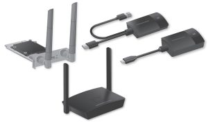
Accessories
Check that you have the accessories and items shown.
WPS Basic Set TY-WPS1 / TY-WPS1W
WPS Receiver
(TY-WPR1 / TY-WPR1W)…………….1
AC adaptor
TY-WPS1
(DPVF3514ZA/X1)……………………1
(including 3 conversion plugs)
TY-WPS1W
(DPVF3699ZA/X1)……………………1
(including 4 conversion plugs)
USB extension cable
(DPVF3513ZA/X1)……………………..2
WPS Transmitter
(TY-WPB1 / TY-WPB1W)…………….2
AC adaptor cable
(DPVF3515ZA/X1)……………………..1
Receiver mounting bracket
(see page 47)…………………………….1
Transmitter case
(TY-WPC1)………………………………..1
HDMI cable
(DPVF3512ZA/X1)……………………..1
WPS USB-C Basic Set TY-WPSC1 / TY-WPSC1W
WPS Receiver
(TY-WPR1 / TY-WPR1W)…………….1
AC adaptor
(DPVF3699ZA/X1)……………………1
(including 4 conversion plugs)
Conversion adaptor for pairing
(DPVF3516ZA/X1)……………………..1
WPS USB-C Transmitter
(TY-WPBC1 / TY-WPBC1W)………..2
AC adaptor cable
(DPVF3515ZA/X1)……………………..1
Receiver mounting bracket
(see page 47)…………………………….1
Transmitter case
(TY-WPC1)………………………………..1
HDMI cable
(DPVF3512ZA/X1)……………………..1
WPS Transmitter Set TY-WP2B1 / TY-WP2B1W
WPS Transmitter
(TY-WPB1 / TY-WPB1W)…………….2
Transmitter case
(TY-WPC1)………………………………..1
USB extension cable
(DPVF3513ZA/X1)……………………..2
WPS Transmitter TY-WPB1 / TY-WPB1W
WPS Transmitter
(TY-WPB1 / TY-WPB1W)…………….1
USB extension cable
(DPVF3513ZA/X1)……………………..1
WPS USB-C Transmitter Set TY-WP2BC1 / TY-WP2BC1W
WPS USB-C Transmitter
(TY-WPBC1 / TY-WPBC1W)………..2
Transmitter case
(TY-WPC1)………………………………..1
Transmitter case
(TY-WPC1)………………………………..1
WPS USB-C Transmitter TY-WPBC1 / TY-WPBC1W
WPS USB-C Transmitter
(TY-WPBC1 / TY-WPBC1W)………..1
Conversion adaptor for pairing
(DPVF3516ZA/X1)……………………..1
Wireless Presentation System Receiver Board TY-SB01WP
Receiver Board
(TY-SB01WP)…………………………….1
Attention
- Store small parts in an appropriate manner, and keep them away from young children.
- The part numbers of accessories are subject to change without notice.
(The actual part number may differ from the ones shown above.) - In case you lost accessories, please purchase them from your dealer. (Available from the customer service)
- Dispose of the packaging materials appropriately after taking out the items.
Part Names
■Receiver (TY-WPR1 / TY-WPR1W)

* HID device
A compatible mouse and a touch module built into the display operate. For information on operable touch modules, see the
Panasonic information site. When using the BQ1 touch panel to operate an externally connected device (PC), change the settings of the BQ1 unit. (page 46)
These can be used only with one screen display. After the USB cable of the HID device is connected, “Hid Driver loading…” appears. When this message disappears, the device can be used.
- Antenna
- FUNCTION button / LED
Used to save a pairing file to the USB memory. - Indicator
Displays the power supply status, and connection statuses of LAN and USB. - Screw holes for the mounting bracket (page 47)
Used to attach the receiver to the mounting bracket.
▼ Connection terminals / Controls - Security Slot
▼ Connection terminals / Controls
This security slot is compatible with a
Noble Wedge slot. - Power input terminal
- Power button
Turns ON/OFF the power of the receiver. - Reset button
Restores the product to the factory default state.
This is the same operation as that when
[Reset RX] is selected for [Reset to
Factory Default]. (page 37)
Reset operation starts when the reset button is pressed for 5 seconds or more while the power is being supplied.
Initialization will be complete in approx.
1 minute. - USB terminal (Type-A)
Connects the transmitter or USB memory when pairing devices.
Use this by connecting an HID device. - LAN terminal (RJ45)
Connects to the network to change the settings of the product. - HDMI output terminal
Connects an imaging device equipped with HDMI input
■ Receiver board (TY-SB01WP)

- Antenna
▼ Connection terminals / Controls - FUNCTION button
Used to save a pairing file to the USB memory. - LAN terminal (RJ45)
Connects to the network to change the settings of the product. - USB terminal (Type-A)
Connects the transmitter or USB memory when pairing devices.
Use this by connecting an HID device (mouse, touch module). (page 9) - FUNCTION LED
Displays the pairing status.
▼ Connection terminals / Controls - Power Indicator
Displays the power supply status, and connection statuses of LAN and USB. - Reset button
Restores the product to the factory default state.
Reset operation starts when the reset button is pressed for 5 seconds or more.
■ Transmitter (TY-WPB1 / TY-WPB1W)

■ USB-C transmitter
(TY-WPBC1 / TY-WPBC1W)

- HDMI input terminal
Connect to an imaging device equipped with HDMI output. - USB terminal (Type-A)
Connect to a USB power supply device. - Main button / LED
Switches between on and off of image display. - Sub button / LED
Switches to the multi-screen mode. - Mode switch
It is used when pairing. (see page 20) Set the switch to the STD side when receiving information from an HID device. - USB terminal (Type-A)
Connects a USB memory when pairing with the receiver. - USB terminal (Type- C)
Connect to an imaging device with a USB Type-C terminal that supports DisplayPort Alt Mode output.
■ Transmitter case
2 transmitters and the USB extension cable (supplied with the TY-WPS1 / TY-WPS1W / TY-WP2B1 / TY-WP2B1W / TY-WPB1 / TY-WPB1W) can be stored.

Connection
Before connection, carefully read the operation manual of the device to be connected to this system.
Turn off the power of each device before connecting cables.
Connecting the receiver
- Connect the AC adaptor and AC adaptor cable to the receiver for the power supply.
Use an AC adaptor conversion plug that fits the shape of the outlet.
<How to remove>
1. Press the button
2. Remove the plug
• Do not remove the AC adaptor conversion plug while it is connected to the outlet. - Connect a display device such as a display and projector to the receiver with HDMI cable.
• For power supply to the receiver, use the supplied AC adaptor or a USB power supply device with 5 V/2 A. - Press the power button of the receiver. When a standby screen is displayed on the display device, the receiver has completed preparation.


Connecting the transmitter
- Connect the USB terminal and HDMI input terminal of the transmitter to the image output device.
•For power supply to the transmitter, 5 V/0.9 A power supply is necessary.
Note
• The USB Type-C terminal of an image output device requires the following functions. Confirm the specifications of the device before using.
• DisplayPort Alt Mode (image output function)
• Function to supply power to the connected device (5 V/0.9 A) - Main LED changes from red blinking (connecting) to white illumination (standby).


Installation of the receiver board
The installation instruction below is based on the flat panel display SQ1 series as an example.
For attaching or removing this product to or from the flat panel display unit, it is recommended to ask a qualified technician or sales dealer. A malfunction may occur due to static electricity, etc. Consult the sales dealer.
Follow the steps below.
Note
- Be sure to turn off the display unit and connected devices, remove the power plug from the socket, and disconnect the cables from the display.
- When attaching/removing the receiver board, do not allow the metal to damage the back cover or display label.
- Remove one screw from the side with the guide on the SLOT adaptor.
- Fit the circuit board of the receiver board in the guides of the SLOT adaptor, and bring the circuit board into contact with the hook (one location) and the end faces (two locations) securely.
- Using the screw removed in step 1, fix the receiver board to the SLOT adaptor.
Note
● Firmly tighten the screw, and check that the hook of the SLOT adaptor fixes the circuit board.
● Check that the surface of the SLOT adaptor and the surface of the circuit board match each other when the receiver board with the SLOT adaptor attached is viewed from the opposite side of the cover. - Remove the 2 screws, and then remove the slot cover or receiver board from the display unit.
To remove the receiver board, hold the handle of the receiver board and pull it out slowly in the arrow direction. - Insert the receiver board to the main unit slot, and tighten the 2 screws.
Fix the receiver board with the 2 screws removed in step 4.
Note
• When replacing another receiver board with this product, the customer shall keep the replaced receiver board for future repair or servicing. - Turn on the display.
- Switch the input of the display to [SLOT].
- Pair the receiver board and the transmitter. (when connecting for the first time, see page 20)
- When the standby screen appears on the display, preparation of the receiver board is complete


Basic Use
Single connection
This section describes how to display an image using one transmitter.
- Press the main button of the transmitter while the standby screen is displayed.
(The screen returns to the standby screen as well.)
• When using multiple transmitters, the image is switched to the image of the transmitter of which the main button is pressed.

Multi connection
This section describes how to display images simultaneously using multiple transmitters.
Images of up to 4 transmitters can be displayed simultaneously.
- Press and hold the sub button of the transmitter for 1 second or more during full-screen display.
The sub LED changes to green illumination, and the multi-screen mode is enabled. - Press the main button of the transmitter to which the image is to be added.
• Audio is not output during multi-screen display.
Multi-screen mode cancellation
Press and hold the sub button of the transmitter for 1 second or more.
• The sub LED changes from green illumination to OFF state, and the multi-screen mode is canceled.
• The multi-screen mode can be canceled only when the main LED is lighting green.


Fixing image switching (fixed mode)
When images of 1 transmitter are displayed with multiple transmitters paired and used, you can make a setting that prohibits switching to images of another transmitter.
This setting prevents accidental image-switching operation
Setting the fixed mode
Press and hold the main button of the transmitter for 1 second or more while an image of one transmitter is displayed.
The main LED changes from green illumination to blue illumination and the fixed mode is enabled.

Canceling the fixed mode
Press and hold the main button of the transmitter for 1 second or more.
The main LED changes from blue illumination to green illumination and the fixed mode is canceled.

Transmitter Extension Method (Pairing)
Pairing settings have been made for the transmitter and receiver of TY-WPS1 / TY-WPS1W / TY-WPSC1 /
TY-WPSC1W Basic Set.
Pairing by connecting the receiver and transmitter
- Slide the mode switch to the STD side.
- Connect the USB terminal of the transmitter to the USB terminal of the receiver/receiver board.
“Pairing…” (pairing in progress) is displayed on the standby screen. - The pairing is complete.
“Pairing OK” is displayed and the LED of the receiver lights up in white. - Remove the USB cable of the transmitter from the receiver.


Pairing by saving a file to the USB memory
Supported device
● Commercially available USB memory devices are supported. (Those with security functions are not supported.)
● USB memory devices other than those formatted in FAT16 or FAT32 cannot be used.
● Up to 32 GB of USB memory in size are supported.
● Only single partition configuration is supported.
● Be sure that the USB memory contains no files before using.
- Connect the USB memory to the USB terminal of the receiver/receiver board.
- Press the FUNCTION button.
The LED lights up in white and the pairing file is saved to the USB memory. - Remove the USB memory.
- Slide the mode switch to the EXT side.
- Supply power to the transmitter.
- Connect the USB memory to the USB terminal of the transmitter.
- The pairing is complete.
The main LED of the transmitter lights up in white. - Remove the USB memory from the transmitter.


About LAN Connection
Since this product is equipped with a network function, connecting the product to a network by wire or wirelessly enables remote control of the product. The Internet needs be accessible from the connected network in order to update the software of the receiver and transmitter.
■ Wired LAN connection

In the initial setup, connecting the LAN terminal of the receiver to the network allows the IP address of the receiver to be automatically assigned by the router using the DHCP function. The assigned IP address is displayed on the standby screen (page 25 ). To manage the receiver (TY-WPR1/TY- WPR1W) / receiver board (TY-SB01WP), use this IP address for the connection.
Note
- For LAN cable, use shielded cable, otherwise, picture noise may be caused.
- Touching the LAN Terminal with a statically charged hand (body) may cause damage to the device due to its discharge.
Do not touch the LAN Terminal or the metal part of the LAN cable.
■ Wireless LAN connection
Using the wireless function of the receiver (TY-WPR1/TY-WPR1W) / receiver board (TY-SB01WP) enable the product to be connected to an external wireless access point or mobile wireless LAN router (only for 5GHz wireless LAN), and an external network or the Internet.
Make the connection setting in [Network Management] on the Web setting screen. (page 30)
Note
• Connecting to a network and displaying an image (mirroring) using the wireless LAN connection function of this product increases the possibility of the image being stuck or noise being generated.
It is recommended that connections to an external wireless LAN be restricted to the cases such as the execution of firmware updates.
Using with Android device (Android 5.0 and later versions)
Using the following two methods allows images on an Android device to (Android 5.0 and later versions supported) be projected (mirroring) on a display or projector. Wireless LAN, security measures, etc. can be used according to the usage environment.
- Use an app on the Android device and connect the device to the wireless LAN coming from the receiver.
- Use an app on the Android device and connect the device to the external wireless LAN.
1 Use an app on the Android device and connect the device to the wireless LAN coming from the receiver
When mirroring is performed with this method, the Android device cannot be connected to the Internet.
Use method 2 to perform mirroring with the device connected to the Internet.
- Connect the receiver to the display device with the HDMI cable, and turn on the receiver. (page 12)
The standby screen appears. “About the standby screen” (page 25) - Install the dedicated app [PressIT] on the Android device from the Google Play Store.
You can also scan the QR code below to install the app. - Connect the Android device to the wireless LAN coming from the receiver.
SSID and a password necessary for wireless LAN connection are displayed on the lower left of the standby screen.
Turn on the wireless LAN function of the Android device and select the SSID displayed on the standby screen.
* For the Android device setting method, see the user’s manual of your device. - Start up the [PressIT] app.
An image with the same design as that of the transmitter is displayed on the Android device. Tap the main button of the transmitter on the screen. (The Android OS may provide a notification. Operate the device according to the notification.) - Mirroring starts.

2 Use an app on the Android device and connect the device to the external wireless LAN
Note
• Before installing the dedicated app, make sure that the receiver and Android device are connected to the same wireless LAN. (page 28)
- Connect the receiver to the display device with the HDMI cable, and turn on the receiver. (page 12)
The standby screen appears. “About the standby screen” (page 25) - Install the dedicated app [PressIT] on the Android device from the Google Play Store.
You can also scan the QR code below to install the app.https://play.google.com/store/apps/details?id=com.panasonic.pressit
The app can also be installed from the Web setting screen. (page 30)
- Start up the [PressIT] app.
An image with the same design as that of the transmitter is displayed on the Android device. Tap the main button of the transmitter on the screen to display. (The Android OS may provide a notification. Operate the device according to the notification.) - Mirroring starts.

■ About PressIT app


- Click [Search Device] to display the list of receivers (SSIDs that have been set) on the connected network.
Make a connection to the display device. - Performs the same operation as that of the main button of the transmitter.
- Performs the same operation as that of the sub button of the transmitter.
- Displays the Android app information.
The illustration at left shows the connected state. In this case, images are displayed.
When returning to the home screen or operating another app without exiting the app, those images are projected (mirroring).
Note
- Copyright-protected content cannot be displayed.
- Motion pictures may not be displayed smoothly depending on the processing capability of the Android device or network conditions.
- When making connections on the network to which multiple receivers are connected, there are multiple display devices. Make sure that correct display devices are connected.
Setting
Connect to the Web page of the receiver to configure the settings of this system.
About the standby screen
Turn on the receiver to display the standby screen on the display device.
Note
• For connecting the receiver and display device, see “Connecting the receiver” (page 12).

- Displays the number of mobile devices connected via wireless LAN of the transmitter or receiver.
- Displays the number of mobile devices connected via external wireless LAN.
- Displays SSID. This is used when directly connecting from PC or mobile devices.
- Displays the password. This is used when directly connecting from PC or mobile devices and when connecting to the Web page immediately after purchase or after initialization of data.
- Displayed when a mouse or a touch module of the display is connected to the USB terminal of the receiver.
- Displayed when connected to a wireless access point or router.
- Displayed when connected to an external network (LAN) via a wired LAN or external wireless LAN access point.
- Use this IP address when connecting from an external network to the receiver.
- Receiver’s IP address for wireless LAN. Use this IP address for wireless LAN connection.
- Displays the QR code linked to the site for downloading the operating instructions
Note
Select [Device Management] – [Language] to change the displayed language. (page 31)
■ When connecting for the first time immediately after purchase
User ID and password are required when connecting to the Web page of the receiver immediately after purchase or after initialization by pressing the reset button of the receiver. Then, the password needs to be changed.
User ID: PressIT_admin
Password: Enter the password ( ) displayed on the standby screen.


Displaying the Web setting screen
■ About web browsers
We recommend using the web browsers shown below to operate the Web setting screen.
Chrome Version 85.0.4183.83 and later versions Internet Explorer 11
Edge Version 84.0.522.52 and later versions
Firefox Version 80.0.1 and later versions
Safari Version.13.0.5 and later versions
■ When configuring the settings in an environment without a wireless access point in the surrounding area
Connect to the wireless LAN of the receiver and open the Web setting screen. Note that while operating the web settings using this method, the mobile device cannot be connected to the Internet temporarily. SSID and a password necessary for wireless LAN connection are displayed on the lower left of the standby screen.

- Turn on the wireless LAN of the PC or mobile device and select SSID displayed on the standby screen.
Above example: PressIT-A132F34D - Enter the wireless LAN password.
Above example: 75847328 - After the connection is complete, enter the IP address displayed on the lower right of the standby screen into the address bar of the web browser, and press Enter.
When the connection is established correctly, the Web setting screen is displayed.
Web setting screen when accessed from PC


■ When configuring the settings in an environment where wireless LAN (5GHz band) access point can be used freely
Connect the receiver to the external wireless LAN and open the Web setting screen. You can also connect to the external wireless access point different from the wireless access point coming from the receiver to open the Web setting screen. The advantage of this method is that logging in to the Web setting screen is possible with the mobile device connected to the network. However, the password of the external wireless access point must be obtained beforehand.
Obtain the password, etc. from the system administrator managing the local network.
- After opening the Web setting screen with the procedure in “When configuring the settings in an environment without wireless access point in the surrounding area” (page 27), log in with administrator privileges and select “Network Management”
- Click “Connect to 5GHz Wireless”.
- Select SSID to connect and enter the password.
- To open the Web setting screen from the PC or mobile device, confirm that it is connected to the same wireless access point as that of the receiver, enter the IP address displayed on the lower right into the address bar of the web browser, and press Enter.


Configuring various settings on the Web setting screen
Settings including [Device Management], [Network Management], and [Detail Settings] can be changed on the Web setting screen.

■ Download Android APK
The Android app (page 23) can be downloaded and installed. Use this app when the device cannot be connected to the Google Play Store. When the app is downloaded from the Web setting screen, confirmation is required to install the app on the Android device since it is not the one downloaded from the Google Play Store. Confirm the version information of the Android device/Android OS.
■ Network Management
The receiver can be connected to an external wireless LAN via an external wireless access point.
Note
• A wired LAN cannot be used in combination.
● Connect to 5GHz Wireless

ON: Stores the external wireless access point settings in the receiver.
OFF: Deletes the external wireless access point settings stored in the receiver.

■Device Management
The Web setting screen has setting options such as Language, Resolution, and Max Connection.
●Language

Supports major languages including Japanese, German, French, and Chinese. The Web setting screen and standby screen are displayed in the selected language.
● Resolution
The standard output resolution is 3840 x 2160 (30fps). Up to 3860 x 2160 (30fps) or 4096 x 2160 (24fps) of resolution is supported. 3840 × 2160 (30fps) is generally called 4K.

● Max Connection

You can decide the number of transmitters and mobile devices connected to the receiver. Up to 32 mobile devices can be connected. The initial setting is 4 devices.
Note that the more the connected devices, the less the network bandwidth of each user.
● Screen mode

Adjusts the size of images.
Fit to Screen: Displays images with the aspect ratio of input signals.
Stretch to Full Screen: Displays images in full screen.
● Timed Restart

Restarts after 8 hours when no operation is performed.
● HDMI-CEC control

Sets the link function with a display or projector.
Note
• This product does not support VIERA LINK.
● HDCP
When connecting the product to an HDCP-incompatible device, set this to [Off].

Note
• Switching the setting [On]/[Off] restarts the product automatically.
■ Detail Settings
This setting function is designed mainly for persons in charge of the information system department and network administrators, enabling more detailed setting changes.
● Wireless Channel
Channel
Bandwidth

* Note that when the receiver is connected to an external wireless access point, the wireless channel cannot be set.
● LAN IP Settings
Network settings can be manually configured including IP address, gateway, netmask, and DNS server.

● SSID
Changes the name of SSID, hides SSID and disables SSID.
* Be sure to take a note before setting.


Turn Off SSID: Setting this to [ON] disables the SSID function of the receiver.
Communication is disabled between transmitter and receiver.
Even if the pairing is performed, communication is disabled.

● Password
Changes the wireless LAN connection password for the receiver. The administrator can hide the wireless LAN password on the standby screen for security enhancement.
Note
• Changing the password requires pairing again.

● My Screen
Uploading an arbitrary image allows the background of the standby screen to be changed. The image size should be less than 2 MB with 1920 x 1080 in PNG format.
Note
• Note that once the background is changed, the product needs to be initialized to restore the image to the original one. (page 37 “Reset to Factory Default”)

● Administrator Password
Changes the administrator password. It is recommended to change the administrator password periodically for security enhancement.

● Screen Saver
Specify the time until the screensaver is activated.
When the screensaver is activated, the image being projected disappears.
Pressing the main button of the transmitter cancels the screensaver.

● WPA/WPA2 Enterprise
Using this function, an electronic certificate key file supporting encryption communication can be uploaded. This function is designed for persons in charge of information system department and network administrators.
● Upgrade

The firmware of the receiver and transmitter can be to the latest versions. This product needs to be stably connected to the Internet to upgrade the firmware.
It is strongly recommended to use the same firmware version for the receiver and transmitter upgraded of this product.
The firmware can be upgraded with the following method.
- Connect the transmitter to an external power source.
- Confirm that the receiver is connected to the Internet and the receiver and transmitter have been paired.
- Click the [Select All] check box to upgrade all the firmware of the receiver and transmitter collectively.
- Tap the [Update] button to start downloading the latest firmware. This process will finish in a few minutes. Please wait for a while.
Note
- The firmware upgrade information displayed for [Upgrade] on the [Detail Settings] menu shows the confirmation result of the receiver version.
- When the firmware upgrade for the receiver is available, a mark to prompt you to upgrade the firmware is displayed on the receiver at the lower right of the standby screen.
● Download Pairing File
Download the pairing file and save it on a USB flash drive.
After downloading is complete, perform step 5 and the subsequent steps in “Pairing by saving a file to the USB memory” (page 21) to copy the pairing file to the transmitter.
The receiver and transmitter of the TY-WPS1/TY-WPS1W basic set are paired at the time of shipment. When the transmitter is initialized or a new transmitter is additionally purchased, pairing with the receiver is required before using.
● Background Color setting
Specify the background colors for the standby screen and no-signal image.
[Black] or [Blue] can be specified.
Note
• When the [My Screen] is specified, this setting is not reflected.

● Date/Time setting

Specifies the time zone and the display style of date displayed on the standby screen.
Date Format:
Refer to [Date/Time setting] (page 41).
Time Server:
Sets the NTP saver.
When the NTP server is not specified, a server registered beforehand is accessed.
Date and time shows the following information.
- Information obtained from the NTP server via wireless LAN or wired LAN of the receiver (priority)
- Information from HDMI-CEC of the corresponding display or projector
● Reboot

Restart the product when the firmware is upgraded to the latest version or the receiver does not respond.
Tap [Reboot] and select [YES].
● Reset to Factory Default

Initializes this product to the default state. Note that the customized language setting, resolution setting, wireless LAN setting, etc. once stored are initialized.
(SSID is not initialized.)
When the transmitter is initialized, the paired state between the receiver and transmitter is canceled. Perform pairing according to the procedure in
“Transmitter Extension Method (Pairing)” (page 20) after initialization.
Reset RX:
Initializes the receiver only.
Reset TX:
Initializes the transmitter only.
Reset RX + TX:
Initializes both the receiver and transmitter.
■ About Device
Displays [SSID], [Firmware Version], [Wireless Channel] and other basic information related to this product.
When the transmitter is connected, the basic information of the transmitter is also displayed.

■ Software licenses
Displays the software license description.
[Setup] menu (display setting)
When this product is connected to the compatible display and the [Setup] menu is set, the following functions can be used.
This section explains each setting using the display SQ1 series as an example. For settings on other models, see the Panasonic information site.
■ Signal
Examples of [Signal] submenu screen
When HDMI is sele