Panasonic FV-KTB2T61HK Range Hood Installation Guide

Range Hood Household use
Model No. FV-KTB2T61HK


Thank you for choosing Panasonic products.
- Please read Operation/Installation Instructions carefully before installing, operating, and maintaining Panasonic products.
Especially, pay attention to “Safety precautions” (pages 2 ~ 4) “Safety precautions” (pages 2 ~ 4). Failure to follow the instructions in this manual may result in personal injury or property damage. - After installation, please explain to the user how to operate and maintain Panasonic products, and give this manual to the customer for safekeeping.
- Please keep the manual properly for future reference. (Kept for future use)
- This unit contains reusable materials, so please assist in proper disposal or recycling when discarding them to protect the environment.
- The right of final interpretation of this manual belongs to Panasonic Corporation.
Safety precautions
Please make sure to follow these instructions!
To avoid harm to you and others, be sure to observe the following safety precautions herein, and refer to the meaning of various signs below.
- The following two results may occur if such signs are ignored or misunderstood.

The symbols are classifi ed and explained as follows.


- Do not bake this product directly on the stove.
(Accessible parts may become hot when used with cooking appliances.) - Do not use this product in humid places.
- Do not bake this product directly on the stove.
(So as not to cause fi res or malfunction.) - Do not touch the power plug with wet hands.
(So as not to cause electric shocks.) - Do not insert sharp metal into any gaps in the unit.
(So as not to touch the inside of the unit and cause electric shocks.) - Do not install, remove, disassemble, modify or reinstall this product by yourself.
(So as not to cause malfunctions, fi res, electric shocks or other accidents.) - Do not put any objects on this product.
(So as not to cause a malfunction or injury.) - Do not use this product on the gas range when gas leakage may occur.
(So as not to cause gas explosion.) - Do not install this product on the wall of flammable materials (such as a wooden wall, etc.).
(So as not to cause fi res.) - The air must not be discharged into a flue that is used for exhausting fumes from appliances burning gas or other fuels.
(So as not to cause fires.) - Be sure to use a 10 A, 220 V AC power socket separately.
(So as not to cause fi res.) - Be sure to remove the power plug before cleaning the product.
(So as not to cause electric shocks.) - There is a fi re risk if cleaning is not carried out in accordance with the instructions, the details concerning the method and frequency of cleaning, please see the instructions.
(If the range hood is not cleaned and maintained according to the instructions specifi ed in the manual, it may catch fire.) - When inserting or removing the power, hold the power plug itself instead of pulling the supply cord as you like.
(So as not to cause fires or electric shocks.) - There shall be adequate ventilation of the room when the range hood is used at the same time as appliances burning gas or other fuels.
(So as not to cause intoxication.) - Stop using this product immediately when oil catches fi re during cooking.
(So as not to cause fi res.) - Stop using this product, and turn off the power switch or remove the power plug in case of any anomaly/malfunction.
(So as not to cause fi res or electric shocks.)
Examples of abnormal failures:
• Abnormal noise or heat.
• An unusual smell/smoke emitted.
• Burning. - This product shall be installed by professionals, and it shall be installed firmly and horizontally.
(So as not to cause injury due to falling of the product.) - Be careful when removing the unit to prevent it from dropping or falling accidentally.
(So as not to cause injury due to falling of the product.) - It shall be grounded. Connect the power plug to a power socket with a grounding continuity terminal.
(So as not to cause electric shocks in case of malfunction or leakage.)

- Do not unscrew the fan grille to clean the inside of the product.
(So as not to cause cuts due to internal sharp edges.) - Do not spray water or detergent directly on the motor and plug.
(So as not to cause electric shocks.) - Do not use a steam cleaner to clean this product.
(So as not to cause malfunctions or electric shocks.) - Do not install it in a humid place.
(So as not to cause electric shocks.)
Safety precautions
Please make sure to follow these instructions!

- Wear gloves when cleaning. (So as not to cause hand injury by the edge of the product.)
- If the supply cord is damaged, it must be replaced by the manufacturer, its service agent similarly qualified persons. (So as not to cause electric shocks or hazards.)
- If the interior needs cleaning, entrust a professional to do so.
- This appliance is not intended for use by persons (including children) with reduced physical, sensory or mental capabilities, or lack of experience and knowledge unless they have been given supervision or instruction concerning use of the appliance by a person responsible for their safety. Children should be supervised to ensure that they do not play with the appliance. (So as not to cause burns, injuries or electric shocks.)
- The minimum distance shall be at least 650 mm between the supporting surface for the cooking vessels on the hob and the lowest part of the product. (So as not to cause malfunctions or burns due to high temperature of the unit.)
- Be sure to install this product on the wall, and make sure that the metal parts and mounting screws do not touch any metalwork in the wall, such as metal slats, cable slats and metal plates. (So as not to cause electric shocks.)
- The product shall be installed on a wall that is strong enough. If installation strength cannot be ensured, reinforcement measures are a must. The wall used to support the installation of this product shall be able to bear the weight 5 times of the product. (So as not to cause injury due to falling of the unit.)
- The range hood is only intended to be installed over a hob with no more than four hob elements. (CAUTION: Accessible parts may become hot when used with cooking appliances.)
Precautions for use
- Do not use gasoline, benzene, thinner or any other similar chemicals for cleaning.
- When using a gas range, it is suggested to turn on this product.
- When using with cooking utensils at the same time, the accessible parts may become hot.
- When using steam to clean the range hood, the steam may hit the electronic components, causing damage to the components or leading to a short circuit.
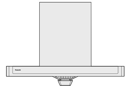
Part names and sizes

※Dimensions (L ×W):141.5 mm ×29.5 mm
Max. input power:1.5 W
Voltage input: DC 12 V

How to use

Insert the plug into the power socket. With a beep, all the buttons on the control panel light up and last for about 2 seconds, and then go out.
Power on/off
Touch the
Fan speed setting
In standby state, touch the
When touching the fan speed button showing white highlight in the working state of the fan, the fan will stop running with a beep.
Ultra high speed
In the standby state, touch the
Light on/off
In the power-off state, touch the
In the power-off state or working state of the fan, touch the
Automatic vent
In the standby state, touch the
Touch
Touch the
Latency switch function
Touch the
→ If the light is on, touch the
→ If the automatic vent function is on, touch the
→ If you touch the
→ If you touch the


Cleaning and maintenance
Daily cleaning
To achieve the best operating performance and longer service life, this product must be cleaned and maintained frequently. Turn off the power before cleaning and maintenance. It is suggested that all surfaces be cleaned with a damp cloth (neutral detergent is
applicable) to keep this product clean and tidy.

Tips
- Usually, just wipe the surface and edges of the range hood.
- It is suggested that it be wiped every two weeks.
Oil cup cleaning
- Remove the oil cup with reference to the figure on the right (the direction to remove oil cup).
- Pour out the oil collected and soak the oil cup in warm water with diluted neutral detergent at a temperature of 40 ℃ to 50 ℃, wait for 5 to 10 minutes and clean the oil cup.
- Put the oil cap back in place with reference to the figure on the right (the direction to install oil cup).

Tips
- It is suggested that the oil cup be cleaned when the oil collected reaches about 80% of the capacity of the oil cup.
- Grasp the oil cup with both hands when removing the oil cup, otherwise, oil in the oil cup may shake and overflow.

Tips
- When removing the fan grille, support it all the way to prevent it from falling.
- Installation of fan grille: install it in a way opposite to the removal procedure, and make sure that it is installed in place.
- Pay attention to sharp edges around the product to avoid being cut when removing the fan grille.
- Do not use abrasive powder, metal brushes, nylon brushes (containing abrasives), or scouring pads, etc. to clean or scrub the fan grille.
- Do not use strong alkaline detergent to clean the fan grille. (So as not to cause malfunction or damage to the fan grille.)
→ Entrust a professional to remove and install the fan grille.
Troubleshooting of common faults
In case any fault occurs, check it according to the table below. If the problem still exists, contact the Customer Consulting Service Center.
| Symptom | Possible causes | Solutions |
| The light is not lit and the motor does not work | 1. The power plug is not inserted into the power socket. 2. The product wire fails. |
1. Insert it into the power socket. 2. Contact the Customer Consulting Service Center. |
| The motor does not work | The motor or capacitor fails. | Contact the Customer Consulting Service Center. |
| The light is not lit | 1. The light wire or connection fails. 2. The light circuit board fails. 3. The light lamp fails. |
Contact the Customer Consulting Service Center. |
| Abnormal noise | The smoke duct is loose or excessively bent, causing poor airflow. | Contact the Customer Consulting Service Center for reinstalling of the smoke duct. |
| Oil fume absorption is not effective | 1. The smoke duct is loose or excessively bent, causing poor airflow. 2. The range hood is not set at the highest fan speed. 3.00 fume is blown off or blown away due to high air volume in the kitchen. 4. The distance between the cooking stove and the range hood is too far. |
1. Contact the Customer Consulting Service Center for reinstalling of the smoke duct. 2. Set to the highest fan speed. 3. Keep the windows or door closed in a proper way. 4. Reinstall the range hood with a reduced cooking stove. |
| Oil leakage | 1. The installation position of the range hood is inclined, which makes it impossible for the oil to flow into the oil cup. 2. The oil cup is full. |
1. Contact the Customer Consulting Service Center for reinstalling it. 2. Pour out the oil and clean the oil cup. |
| An abnormal sound is heard when the fan rotor works | The fan rotor is loose, and the fan rotor cap is not tightened. | Contact the Customer Consulting Service Center. |
| Touch buttons do not work properly | The control switch fails. | Contact the Customer Consulting Service Center. |
Electrical schematic diagram

Specifications
| Rated voltage | 220 V ∼ |
| Rated frequency | 50 Hz |
| Rated total input power | 273 W |
| Rated input power of the main motor | 270 W |
| Max. input power of LED lamp | 1.5 W x 2 |
| Number of fans | Single fan |
| Air volume | 18 m3/min |
| Air pressure | 310 Pa |
| Max. static pressure | 360 Pa |
| Airborne acoustical noise | 69 dB ( A 1 |
| Air volume at ultra high speed | 20 m3/min |
| Air pressure at ultra high speed | 330 Pa |
| Max. static pressure at ultra high speed | 380 Pa |
| Noise at ultra high speed | 72 dB ( A I |
| Net weight | 26.0 kg |
| The outer diameter of smoke duct | 0185 mm |
| Dimension L x W x H | 900 mm x 500 mm x 570 mm |
- The data of air volume and electrical properties are valued at a static pressure of 0 Pa.
- Noise: A-weighted sound power level with a tolerance of +3 dB.
- Air volume, air pressure, max. static pressure, air volume at ultra high speed, air pressure at ultra high speed, and max. static pressure at ultra high speed: the allowable difference between the actual measured value and the indicated value shall not exceed -10% of the indicated value.
- Net weight: the weight of the body plus the weight of oil cup and adapter seat.
- The parameters above are subject to change without notice.
List of accessories
| No. | Appearance | Name and usage | Quantity |
| 1 | Duct cover hang board (For fi xing the upper duct cover) | 2 | |
| 2 | Appliance hang board (For hanging the body) | 1 | |
| 3 | Plastic expansion tube | 9 | |
| 4 | Screw ( Φ5 ×53) | 8 | |
| 5 | Slotted fi xing screw (M5 ×10) | 4 | |
| 6 | Screw (ST5 ×19) | 1 | |
| 7 | Oil cup | 1 | |
| 8 | Stop block | 1 | |
| 9 | Operation/Installation Instructions | 1 | |
| 10 | Smoke duct (With aluminum foil tape) | 1 | |
| 11 | Duct adapter | 1 | |
| 12 | Short duct adapter (Fixed on smoke duct) | 1 | |
| 13 | Adapter | 1 | |
| 14 | Sealing pad (Fixed on the appliance) | 1 | |
| 15 | Adapter ring | 1 |


Installation method
1. Checking before installation
Suggested installation of the range hood is as shown in the figure below:

- This product may have sharp edges. Do wear gloves when installing.
- The range hood shall be aligned with the center of the cooking stove.
- Do not install it in a place exposed to direct sunlight.
- Ensure that the gas can be discharged to the outside or common flue through the smoke duct.
2. Installing the unit
- According to Fig.1 (Drilling diagram for installation), use an electric impact drill to make 5 holes with a diameter of 10 mm and a depth of 53 mm at the corresponding positions on the wall where the range hood is installed, embed the plastic expansion tubes, and use 4 screws ( Φ5 ×53) to fi x appliance hang board to the wall.
- According to Fig.2, use a Phillips screwdriver to remove 8 self-tapping screws at the adapter and take out the sealing pad.
- According to Fig.3, align with the screw holes and place the sealing pad and the adapter on the outlet in sequence. After aligning with the screw holes, use 8 self-tapping screws removed in step ② to fi x the sealing pad and the adapter to the unit.
Note: The direction of the adapter after installation shall be the same as that shown in Fig.4. - According to Fig.5, take out the smoke duct and the short duct adapter (both have been fixed with aluminum foil tape), and keep the smoke duct in a compressed state. Pass the adapter ring from top to bottom through the smoke duct and the short duct adapter in sequence to the limit for use, and secure the above components using the four clips of the adapter ring to interlock them with the outlet seat. Connect the power supply, start the motor, and check if the two metal pieces are turned up. Turn off the range hood, and make sure that the two metal pieces drop down naturally.
- Tear off the protective fi lm from the lower duct cover, and securely attach the unit to the appliance hang board with the unit inclined 1 °or 2 °to the wall, so that the hooks of the appliance hang board are fully inserted. After installation, make sure that the range hood is not shaking or detached, and try to ensure that it is in a horizontal state. Stretch the smoke duct, extend it into the wall opening or connect it to the common fl ue securely, and adjust the smoke duct to ensure that it is not bulging or compressed, and it bends freely. If the smoke duct is extended directly into the common fl ue, it shall not go too deep into the common fl ue, so as not to affect exhaust effect; if oil fume is exhausted directly to the outside, it is suggested that a shutter (available in hardware stores) be attached at the end of the outdoor smoke duct.
- Insert the power plug into the socket securely. The power socket shall be a special one with a reliable grounding wire. Do not change the plug without permission.
- As shown in Fig.6, use a screw (ST5 ×19) to fi x the stop block on the wall through a plastic expansion tube to prevent the range hood from falling off vertically in case of an external force.


3. Installing the upper duct cover
- If it is necessary to install the upper duct cover, determine the fi xing hole positions of the duct cover hang board according to Fig.7.
- Use an electric impact drill to make four holes with a diameter of 10 mm and a depth of 53 mm at the corresponding positions on the wall, embed the plastic expansion tubes, and use 4 screws ( Φ5 ×53) to fi x the two duct cover hang the board on the wall.
- Pull out the upper duct cover, adjust the height of the upper duct cover so that the holes on both sides of the upper duct cover are aligned with the anchor holes in the bracket, and secure it in place with 4 slotted fi xing screws (M5 ×10). After installation, tear off the protective fi lm from the upper duct cover.
(Caution: Be careful when taking out the upper duct cover, and pay attention to sharp edges around the product to avoid being cut.)

4. Installing the oil cup
Install the oil cup at the bottom of the unit.

After installation, tear off the protective fi lm from the duct cover.
Test operation
After installation, turn on the power, press each function button on the control panel, and check the following items:
- Do the fan blades rotate properly?
- Is there any abnormal vibration or noise?
- Is each function button on the control panel working properly?
Panasonic Appliances (China) Co., Ltd.
No.2 SongQiao Street, Econmic&Technical Development Zone,
Hangzhou, Zhejiang, China
https://www.panasonic.com
© Panasonic Corporation 2021