Honeywell XF821A Panel Bus Driver for Tridium Niagara User Guide


Introduction
Honeywell Panel Bus is a protocol for IO modules for Honeywell controllers, such as Excel 800, Excel Web II, ComfortPoint Open Plant, LION, EAGLE and EAGLEHAWK 1. The family of these IO modules includes multiple pluggable modules with just one type of IO (analog input, binary input, analog output, relay output and floating / three-position output) or mixture of IO.

Panel Bus modules communicate over RS-485 interface using 115.2 kbps baud rate. They are hot-pluggable – no need to disconnect power to swap them. All addressing is done using one HEX switch. Output modules are available with manual override switches / potentiometers for easy maintenance. Panel Bus modules allow to cover all kinds of applications, which require from tens to hundreds IO points.
For a full description of Panel Bus refer to Panel Bus I/O Modules.
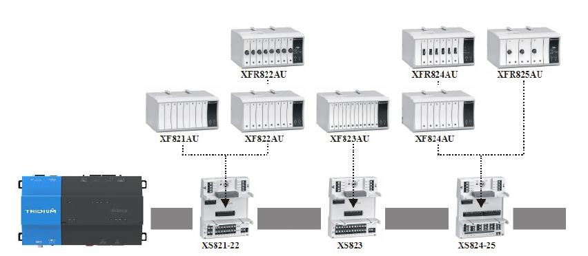
Tridium Niagara driver allows to retrofit Honeywell panels by replacing main controller with JACE or any other Niagara-compatible device (Cylon Integra, Johnson Controls FX, Distech Controls EC-BOS, GC5 iSMA-B-MAC36NL etc.) and keeping all IO modules. That greatly reduces the amount of work and price of the new controller IO. Panel Bus IO points will become available for control by Niagara logic on a standard wiresheet. Each IO point can also be configured, e.g. set thermistor types for inputs or fail-safe value for outputs.
Requirements
- Niagara-powered device such as Jace 8000 or any OEM version
- Jace RS-485 port or serial-to-IP device with Baudrate Virtual Port driver
- Panel Bus driver module and license
Quick Start
- Import panelBus.jar (AX) or panelBus-rt.jar (N4) module with all dependencies into both Jace and WorkPlace, restart both.
- Add Panel Bus Network to the station.
- Enter license code in License property under Panel Bus Network.
- Set COM port under Serial Config / Port Name. Make sure port settings are correct (Panel Bus default settings are 115200/8/1/None).
- Discover devices – you should be able to see IO modules connected to the COM port.
- Add discovered devices to the station.
- Open device Points extension and Discover points.
- Add points to the station. Points shall show their values and output signals could be changed.
Panel Bus Network
Panel Bus Network contains many standard Niagara properties, as well as few driver-specific ones:
- License – the code which allows the driver to run on your host
- Tuning Policies / Default Policy / Read IO Fault Status – whether point status shall be read from IO module and applied to Niagara point. By default it is set to false.
- Tuning Policies / Default Policy / Always Subscribed – whether the point shall always be subscribed: periodically read from IO module.
Normally only License and Serial Config / Port Name shall be changed. It is possible to have multiple Panel Bus Network in Niagara station, each with its own COM port. Points in all networks are counted for licensing purposes.
Panel Bus Device
Panel Bus IO modules are addressed using S2 HEX switch on them, so each module has an address expressed as one hexadecimal digit for 0 to F. Each type of IO modules (AI, BI, AO, BO, mixed) is addressed separately. For example it is possible to have one CLIOP821A module with address 0 and one CLIOP822A with address 0 on the same line.
Panel Bus Device contains the following driver-specific properties:
- Model – IO device model
- Address – Hexadecimal number set by S2 switch on IO module
- Serial – Device serial number, read only
- Firmware – Device firmware version, read only
- Poll Frequency – Frequency of point polling, either Fast, Normal or Slow. Timings are specified in PanelBusNetwork / Poll Scheduler.
Devices can be discovered automatically or added manually. In case of automatic discovery no properties shall be changed.


Panel Bus points are discovered automatically in Panel Bus Point Manager. Each point has the following properties:
- Type – Niagara point type, Boolean or Numeric Point for inputs and Boolean or Numeric Writable for outputs
- Facets – Point units
- Point Type – Panel Bus IO type
- Address – IO number
- IO Type – Panel Bus IO configuration.
Point Type and Address are automatically assigned when points are added to the station from the discovery pane. Type is also automatically selected based on Point Type, but it could be changed if needed.
Analog Input is mapped into Numeric Point by default, but it can also be used as a digital input, then it is mapped into Boolean Point. IO Type allows to setup analog input type: select thermistor curve for passive sensors or 0/2-10V for active ones.
Digital Input is mapped into Boolean Point by default, but it can also be used as a counter input, then it is mapped into Numeric Point.
Analog Output is mapped into Numeric Writable by default, but it can also be used as a digital output, then it is mapped into Boolean Writable. IO Type allows to setup analog output type: 0-10V or 2-10V.
Relay Output is mapped into Boolean Writable. Floating Output is mapped into Numeric Writable.
Proxy Ext / Tuning Policy Name assigns Tuning Policy to each point. This policy determines when the point shall be written to, if the point is always subscribed and if the open / short circuit of analog inputs shall be mapped into point fault status.
All added points are polled by the driver in groups to minimize the traÿc. Polling rate is specified in Panel Bus Device / Poll Frequency property.

Panel Bus Point Config
Panel Bus points have extra configuration parameters, which determine for example whether DI is normally open or close and in which position shall RO remain in case of communication failure. If order to set these parameters PointConfig component shall be copied from panelBus palette under each point. PointConfig automatically displays parameters relevant to parent point type, see below. Driver checks if this component is available and writes its values into the Panel Bus module.
Digital Inputs
- Contact Mode – Normally closed or Normally open
- LED Behavior – IO LED colour to be O˙ / Yellow or Green / Red (except for CLIOP830A / CLIOP831A modules)

Analog Inputs
- Contact Mode – [for digital input mode] Normally closed or Normally open
- Sensor Fail – in case of sensor failure show XXX (Invalid option) or the last good value (Last Position option)
- Noise Filter – limits signal changes to filter out extra noise
- O˙set – an o˙set to correct the value. One can also use ProxyExt / Conversion property to add o˙set on Niagara side
Digital and Analog Outputs
- Direct Reverse – allows to reverse output
- Safety Position – output signal in case of communication fault: 0%, 50%, 100% or keep the last value
Floating Outputs
- Safety Position – output signal in case of communication fault
- End Switches – if the motor has end switches, open and close relays will remain energized at the end positions
- Power Up Sync – the motor will fully close on power-up for synchronization
- Sync 24h – the motor will fully close every 24 hours for synchronization
- Sync Break – if No option is selected, complete synchronization before moving to a new position.
- Close Repeat – after reaching 0%, the close relay will be energized for a short period to fully close its rubber seal
- Valve Exercising – open valve once a week to assure reliable operation
- Open Runtime – time from 0% to 100%
- Close Runtime – time from 100% to 0%
- Sync Charge – how long the relay shall be kept energized after reaching end position during synchronization
- Sync Level Open – synchronize the motor to fully open position if its setpoint is higher than this setting; if the value is 255, disable this function
- Sync Level Close – synchronize the motor to fully closed position if its setpoint is lower than this setting; if the value is 255, disable this function
- Min Stop Time – minimal stop time before changing movement direction
- Min Run Percent – minimal percentage change