Makita DBS180 Cordless Belt Sander Instruction Manual


MAKITA DBS180 Cordless Belt Sander
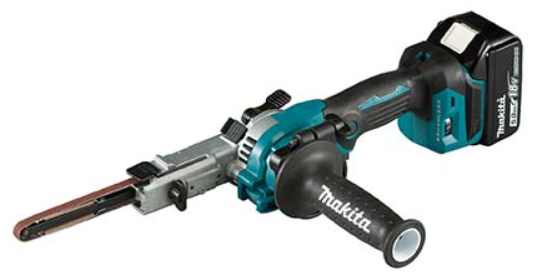


SPECIFICATIONS
| Model: | DBS180 |
| Belt size | 9 mm x 533 mm |
| Belt speed | 600 – 1,700 m/min |
| Overall length | 500 mm *1 |
| Rated voltage | D.C. 18 V |
| Net weight | 2.1 kg |
With abrasive belt and battery cartridge (BL1860B).
- Due to our continuing program of research and development, the specifications herein are subject to change without notice.
- Specifications may differ from country to country.
- Weight, with battery cartridge, according to EPTA-Procedure 01/2014
Applicable battery cartridge and charger
| Battery cartridge | BL1815N / BL1820 / BL1820B / BL1830 / BL1830B / BL1840 / BL1840B / BL1850 / BL1850B / BL1860B |
| Charger | DC18RC / DC18RD / DC18RE / DC18SD / DC18SE / DC18SF / DC18SH |
WARNING: Only use the battery cartridges and chargers listed above. Use of any other battery cartridges and chargers may cause injury and/or fire.
Intended use
The tool is intended for the sanding of large surface of wood, plastic and metal materials as well as painted surfaces.
Noise
The typical A-weighted noise level determined accord-ing to EN62841-2-4:
Sound pressure level (LpA) : 77 dB(A)
Uncertainty (K) : 3 dB(A)
NOTE: The declared noise emission value(s) has been measured in accordance with a standard test method and may be used for comparing one tool with another.
NOTE: The declared noise emission value(s) may also be used in a preliminary assessment of exposure.
WARNING: Wear ear protection.
WARNING: The noise emission during actual use of the power tool can differ from the declared value(s) depending on the ways in which the tool is used especially what kind of workpiece is processed.
WARNING: Be sure to identify safety mea-sures to protect the operator that are based on an estimation of exposure in the actual conditions of use (taking account of all parts of the operating cycle such as the times when the tool is switched off and when it is running idle in addition to the trigger time).
Vibration
The vibration total value (tri-axial vector sum) deter-mined according to EN62841-2-4:
Work mode: sanding metal plate
Vibration emission (ah) : 2.5 m/s2 or less Uncertainty (K) : 1.5 m/s2
NOTE: The declared vibration total value(s) has been measured in accordance with a standard test method and may be used for comparing one tool with another.
NOTE: The declared vibration total value(s) may also be used in a preliminary assessment of exposure.
WARNING: The vibration emission during actual use of the power tool can differ from the declared value(s) depending on the ways in which the tool is used especially what kind of workpiece is processed.
WARNING: Be sure to identify safety measures to protect the operator that are based on an estimation of exposure in the actual conditions of use (taking account of all parts of the operating cycle such as the times when the tool is switched off and when it is running idle in addition to the trigger time).
EC Declaration of Conformity
For European countries only
The EC declaration of conformity is included as Annex A to this instruction manual.
SAFETY WARNINGS
General power tool safety warnings
WARNING: Read all safety warnings, instructions, illustrations and specifications provided with this power tool. Failure to follow all instructions listed below may result in electric shock, fire and/or serious injury.
Save all warnings and instructions for future reference.
The term “power tool” in the warnings refers to your mains-operated (corded) power tool or battery-operated (cordless) power tool.
CORDLESS BELT SANDER SAFETY WARNINGS
- Ventilate your work area adequately when you perform sanding operations.
- Some material contains chemicals which may be toxic. Take caution to prevent dust inhalation and skin contact. Follow material supplier safety data.
- Always use the correct dust mask/respirator for the material and application you are working with.
- Always use safety glasses or goggles. Ordinary eye or sun glasses are NOT safety glasses.
- Hold the tool firmly with both hands.
- Make sure the belt is not contacting the work-piece before the switch is turned on.
- Keep hands away from rotating parts.
- Do not leave the tool running. Operate the tool only when hand-held.
- This tool has not been waterproofed, so do not use water on the workpiece surface.
SAVE THESE INSTRUCTIONS.
WARNING: DO NOT let comfort or familiarity with product (gained from repeated use) replace strict adherence to safety rules for the subject product. MISUSE or failure to follow the safety rules stated in this instruction manual may cause serious personal injury.
Important safety instructions for battery cartridge
- Before using battery cartridge, read all instructions and cautionary markings on (1) battery charger, (2) battery, and (3) product using battery.
- Do not disassemble or tamper the battery cartridge. It may result in a fire, excessive heat, or explosion.
- If operating time has become excessively shorter, stop operating immediately. It may result in a risk of overheating, possible burns and even an explosion.
- If electrolyte gets into your eyes, rinse them out with clear water and seek medical attention right away. It may result in loss of your eyesight.
- Do not short the battery cartridge:
- Do not touch the terminals with any conductive material.
- Avoid storing battery cartridge in a container with other metal objects such as nails, coins, etc.
- Do not expose battery cartridge to water or rain.
- Do not store and use the tool and battery cartridge in locations where the temperature may reach or exceed 50 °C (122 °F).
- Do not incinerate the battery cartridge even if it is severely damaged or is completely worn out. The battery cartridge can explode in a fire.
- Do not nail, cut, crush, throw, drop the battery cartridge, or hit against a hard object to the battery cartridge. Such conduct may result in a fire, excessive heat, or explosion.
- Do not use a damaged battery.
- The contained lithium-ion batteries are subject to the Dangerous Goods Legislation requirements. For commercial transports e.g. by third parties, forwarding agents, special requirement on pack-aging and labeling must be observed.
For preparation of the item being shipped, consulting an expert for hazardous material is required. Please also observe possibly more detailed national regulations. Tape or mask off open contacts and pack up the battery in such a manner that it cannot move around in the packaging. - When disposing the battery cartridge, remove it from the tool and dispose of it in a safe place. Follow your local regulations relating to disposal of battery.
- Use the batteries only with the products specified by Makita. Installing the batteries to non-compliant products may result in a fire, exces-sive heat, explosion, or leak of electrolyte.
- If the tool is not used for a long period of time, the battery must be removed from the tool.
- During and after use, the battery cartridge may take on heat which can cause burns or low temperature burns. Pay attention to the handling of hot battery cartridges.
- Do not touch the terminal of the tool immediately after use as it may get hot enough to cause burns.
- Do not allow chips, dust, or soil stuck into the terminals, holes, and grooves of the battery cartridge. It may result in poor performance or breakdown of the tool or battery cartridge.
- Unless the tool supports the use near high-voltage electrical power lines, do not use the battery cartridge near high-voltage electrical power lines. It may result in a malfunction or breakdown of the tool or battery cartridge.
- Keep the battery away from children.
SAVE THESE INSTRUCTIONS.
CAUTION: Only use genuine Makita batteries. Use of non-genuine Makita batteries, or batteries that have been altered, may result in the battery bursting causing fires, personal injury and damage. It will also void the Makita warranty for the Makita tool and charger.
Tips for maintaining maximum battery life
- Charge the battery cartridge before completely discharged. Always stop tool operation and charge the battery cartridge when you notice less tool power.
- Never recharge a fully charged battery cartridge. Overcharging shortens the battery service life.
- Charge the battery cartridge with room temperature at 10 °C – 40 °C (50 °F – 104 °F). Let a hot battery cartridge cool down before charging it.
- When not using the battery cartridge, remove it from the tool or the charger.
- Charge the battery cartridge if you do not use it for a long period (more than six months).
FUNCTIONAL DESCRIPTION
CAUTION: Always be sure that the tool is switched off and the battery cartridge is removed before adjusting or checking function on the tool.
Installing or removing battery cartridge
CAUTION: Always switch off the tool before installing or removing of the battery cartridge.
CAUTION: Hold the tool and the battery cartridge firmly when installing or removing battery cartridge. Failure to hold the tool and the battery cartridge firmly may cause them to slip off your hands and result in damage to the tool and battery cartridge and a personal injury.
- Fig.1: 1. Red indicator
- 2. Button
- 3. Battery cartridge
To remove the battery cartridge, slide it from the tool while sliding the button on the front of the cartridge.
To install the battery cartridge, align the tongue on the battery cartridge with the groove in the housing and slip it into place. Insert it all the way until it locks in place with a little click. If you can see the red indicator on the upper side of the button, it is not locked completely.
CAUTION: Always install the battery cartridge fully until the red indicator cannot be seen. If not, it may accidentally fall out of the tool, causing injury to you or someone around you.
CAUTION: Do not install the battery cartridge forcibly. If the cartridge does not slide in easily, it is not being inserted correctly.
Tool / battery protection system
The tool is equipped with a tool/battery protection system. This system automatically cuts off the power to extend tool and battery life. The tool will automatically stop during operation if the tool or battery is placed under one of the following conditions:
- Overload protection
This protection works when the tool is operated in a manner that causes it to draw an abnormally high cur-rent. In this situation, turn the tool off and stop the application that caused the tool to become overloaded. Then turn the tool on to restart. - Overheat protection
This protection works when the tool or battery is over-heated. In this situation, let the tool and battery cool before turning the tool on again. - Overdischarge protection
This protection works when the remaining battery capacity gets low. In this situation, remove the battery from the tool and charge the battery.
Indicating the remaining battery capacity
Only for battery cartridges with the indicator
- Fig.2: 1. Indicator lamps
- 2. Check button
Press the check button on the battery cartridge to indicate the remaining battery capacity. The indicator lamps light up for a few seconds.

NOTE: Depending on the conditions of use and the ambient temperature, the indication may differ slightly from the actual capacity.
NOTE: The first (far left) indicator lamp will blink when the battery protection system works.
Adjusting arm inclination
The arm can be pivoted and fixed at any desired angle within the range “A” (-5° to 90°) in the figure. Adjust the angle to make a comfortable working position. Loosen the lock lever by raising it. Pivot the arm to the desired position, and secure the lock lever to fix the arm firmly.
- Fig.3: 1. Lock lever
- 2. Arm
Replacing arm
6 mm (1/4″) and 13 mm (1/2″) width belts can be installed with the optional arms that are designed for the corresponding belt widths. Loosen the screw that secures the arm and replace the standard-equipped arm with the optional arm, then tighten the screw firmly.
- Fig.4: 1. Screw
- 2. Arm
Switch action
WARNING: For your safety, this tool is equipped with the lock-off switch which prevents the tool from unintended starting. NEVER use the tool if it runs when you simply pull the switch trigger without releasing the lock-off switch. Return the tool to our authorized service center for proper repairs BEFORE further usage.
CAUTION: Before installing the battery cartridge into the tool, always check to see that the switch trigger actuates properly and returns to the “OFF” position when released. Operating a tool with a switch that does not actuate properly can lead to loss of control and serious personal injury.
NOTICE: Do not pull the switch trigger hard with-out releasing the lock-off switch. This can cause switch breakage.
NOTICE: The lock-off switch cannot be released while the arm is being pivoted beyond 90°.
To prevent the switch trigger from being accidentally pulled, a lock-off switch is provided. Depress the switch lever ( ) from the A side to unlock the switch trigger, and ( ) from the B side to lock in.
- Fig.5: 1. Lock-off switch
To start the tool, pull the switch trigger. Release the switch trigger to stop.
For continuous operation, pull the switch trigger and then push in the lock button. To stop the tool from the locked switch position, pull the switch trigger fully, and then release it.
- Fig.6: 1. Lock-on button
- 2. Switch trigger
Lighting up the front lamp
CAUTION: Do not look in the light or see the source of light directly.
The lighting direction can be adjusted at three levels through an angle of 60°. Pull the switch trigger to turn on the lamp. To turn off, release it. The lamp goes out approximately 10 seconds after releasing the switch trigger.
- Fig.7: 1. Lamp
NOTE: When the tool is overheated, the light flashes for one minute. In this case, cool down the tool before operating again.
NOTE: Use a dry cloth to wipe the dirt off the lens of the lamp. Be careful not to scratch the lens of lamp, or it may lower the illumination.
Speed adjusting dial
The belt speed can be adjusted between 600 m and 1,700 m per minute (1,970 – 5,600 ft/min) by turning the speed adjusting dial to a given number setting from 1 to 5.
Higher speed is obtained when the dial is turned in the direction of number 5; lower speed is obtained when it is turned in the direction of number 1. Select the proper speed for the workpiece to be sanded.
CAUTION: The speed adjusting dial can only be turned between the numbers indicated on the dial. Do not apply an excessive force to turn the dial outside that range, or the speed adjustment may not function.
- Fig.8: 1. Speed adjusting dial
ASSEMBLY
CAUTION: Always be sure that the tool is switched off and the battery cartridge is removed before carrying out any work on the tool.
Removing and installing abrasive belt
Pull the cam lever back to release the tension in the belt, and remove the belt.
To install the belt, place one side of the belt over the rear pulley in first, hook the other side over the front pul-ley, and then set the cam lever to the original position.
- Fig.9: 1. Cam lever
- 2. Abrasive belt
- 3. Rear pulley
- 4. Front pulley
Adjusting belt tracking
Make sure that the belt is aligned with the arm properly on a trial run at low speed.
Use the thumb screw to center the belt tracking. Turn the screw clockwise to incline the arm to the right when looking down at the tool with its arm pointed forward, and in counterclockwise to the left.
- Fig.10: 1. Arm
- 2. Thumb screw
Installing side grip
CAUTION: Securely tighten the thumb screw before operation.
CAUTION: Avoid exerting a strong external force on the side grip, otherwise the grip base becomes loosely attached and the tool may fall off causing damage or personal injury in the following conditions:
- Apply a full impact on the side grip during operation
- Handle the tool carelessly only with one hand on the side grip
- Carry the tool only with one hand on the side grip
The side grip (auxiliary handle) helps hold the tool firmly during operation.
- Screw the grip into the fastening nut placed in the grip base.
- Fig.11: 1. Grip
- 2. Grip base
- 3. Fastening nut
- Loosen the thumb screw in the grip base.
Attach the base to the barrel of the motor housing align-ing the locking tab on the base with the shallow groove in the surface of the housing.
Tighten the thumb screw to secure the grip.- Fig.12: 1. Thumb screw
- 2. Motor housing
Connecting to Makita vacuum cleaner
CAUTION: Always close the nozzle cap when a vacuum cleaner is not connected to the nozzle. Never insert your finger into the nozzle.
NOTICE: Read the instruction manual supplied with your vacuum cleaner before using it.
NOTE: Optional front cuffs 22, joints or tool adapters may be required to make connections depending on your vacuum cleaner system.
Cleaner sanding operations can be performed by connecting the belt sander to Makita vacuum cleaner. Open the nozzle cap, and install the dust nozzle. Connect the hose of a vacuum cleaner to the dust nozzle.
- Fig.13: 1. Dust nozzle
- 2. Front cuffs / joint / adapter
- 3. Hose of vacuum cleaner
- 4. Vacuum cleaner
OPERATION
CAUTION: Secure workpiece with clamps, etc. if it possibly moves during operation.
CAUTION: Avoid any sanding operations on ignitable materials such as aluminum and magne-sium. It may result in a fire, explosion or risk of injury.
CAUTION: Be sure that not any part of the sanding belt is placed on the surface of workpiece before you turn the tool on or off. Otherwise a poor sanding finish, damage to the belt or loss of control of the tool may result.
CAUTION: Avoid body contact with the belt and rotating parts of the tool during operation. Always be aware of your surroundings and bystanders, and stay alert for possible hazards.
CAUTION: Do not attempt to hold and operate the tool upside down. It may cause a serious acci-dent resulting in personal injury.
Turn the tool on and wait until it attains full speed. Hold the tool firmly with both hands. Gently apply the tool to the work-piece surface and move the tool forward and backward.
- Fig.14
- Fig.15
Always use the range “C” (between the end of flat shoe and front pulley) in the figure to sand the workpiece. Press the belt only lightly on the workpiece. Excessive pres-sure may damage the belt and shorten the life of the tool.
- Fig.16: 1. Flat shoe
- 2. Front pulley
MAINTENANCE
CAUTION: Always be sure that the tool is switched off and the battery cartridge is removed before attempting to perform inspection or maintenance.
NOTICE: Never use gasoline, benzine, thinner, alcohol or the like. Discoloration, deformation or cracks may result.
To maintain product SAFETY and RELIABILITY, repairs, any other maintenance or adjustment should be performed by Makita Authorized or Factory Service Centers, always using Makita replacement parts.
Storage
CAUTION: Be careful not to pinch your fingers when moving the arm. Failure to do so may cause personal injury.
The arm can move through an angle of up to 160°. Fold the arm up to save a storage space.
- Loosen the lock lever by raising it. Pivot the arm at an angle of 90°.
- Push and hold the slider knob, and then adjust the angle of the arm in the range “B” (90° to 160°) in the figure.
- Fig.17: 1. Lock lever
- 2. Slider knob
- 3. Arm
- Secure the lock lever to fix the arm.
- Fig.18: 1. Lock lever
- 2. Lock-off switch
NOTICE: The lock-off switch is automatically activated while the arm is being pivoted beyond 90°.
OPTIONAL ACCESSORIES
CAUTION: These accessories or attachments are recommended for use with your Makita tool specified in this manual. The use of any other accessories or attachments might present a risk of injury to persons. Only use accessory or attachment for its stated purpose.
If you need any assistance for more details regard-ing these accessories, ask your local Makita Service Center.
- Dust nozzle assembly
- Arm (6, 9, 13 mm (1/4″, 3/8″, 1/2″))
- Abrasive belts
- Dust cover complete
- Hose complete 28
- Front cuffs
- Makita genuine battery and charger
NOTE: Some items in the list may be included in the tool package as standard accessories. They may differ from country to country.