Honeywell MFP9720029 Harnesses And Body Belts User Manual


USER
MANUAL

HARNESSES AND BODY BELTS

INSTRUCTIONS FOR USE
Personal Protective Equipment
FULL-BODY HARNESSES AND BODY BELTS
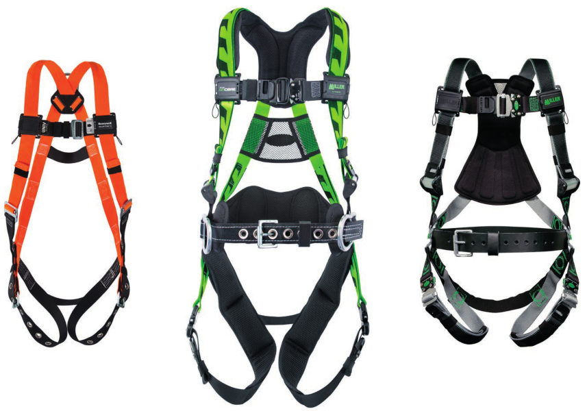
[This user instruction manual covers all Miller and Miller Titan full-body harnesses, as well as body belts (excluding Linemen’s Belts).]
Thank you for your purchase of Honeywell Miller fall protection equipment manufactured by Honeywell Industrial Safety.
All persons using this equipment must read, understand and follow all instructions. Failure to do so may result in serious injury or death. Do not use this equipment unless you are properly trained.

It is crucial that the authorized person/user of this equipment read and understand these instructions. In addition, federal law requires employers to ensure that all users are trained in the proper installation, use, inspection, and maintenance of fall protection equipment. Fall protection training should be an integral part of a comprehensive safety program.
Proper use of fall arrest systems can save lives and reduce the potential of serious injuries from a fall. The user must be aware that forces experienced during the arrest of a fall or prolonged suspension may cause bodily injury. Consult a physician if there is any question about the user’s ability to use this product. Pregnant women and minor children must not use this product.
1 PURPOSE
Honeywell Industrial Safety offers a wide array of full-body harnesses for every application. While full-body harnesses may be used for positioning, travel restraint, and rescue, they are the only acceptable form of bodywear for fall arrest. Harness designs offer superior safety and functionality with features developed to meet key user needs, such as comfort, fit, ease-of-use, style, durability, compliance, flexibility, and convenience.
Always use a full-body harness for fall arrest. Body belts may be used for positioning and travel restraint only.

GENERAL FALL PROTECTION REQUIREMENTS
2.1 General Requirements
The user’s organization shall retain the manufacturer’s instructions and make them readily available to all users.
All authorized persons/users must reference the regulations governing occupational safety, as well as applicable ANSI or CSA standards. Please refer to the product labeling for information on specific OSHA regulations, and ANSI and CSA standards met by the product.
It is essential that the users of this type of equipment receive proper training and instruction, including detailed procedures for the safe use of such equipment in their work application. ANSI/ASSE Z359.2, Minimum Requirements for a Managed Fall Protection Program, establishes guidelines and requirements for an employer’s managed fall protection program, including policies, duties, and training; fall protection procedures; eliminating and controlling fall hazards; rescue procedures; incident investigations; and evaluating program effectiveness.
Full-body harnesses which meet OSHA and current ANSI/ASSE and CSA standards are intended to be used with other components of a Personal Fall Arrest System that limits maximum arrest forces to 1800 lbs (8kN) or less.
Proper precautions should always be taken to remove any obstructions, debris, material, or other recognized hazards from the work area that could cause injuries or interfere with the operation of the system.
Always check for obstructions below the work area to make sure the potential fall path is clear.
Allow adequate fall clearance below the work surface.
To minimize the potential for accidental disengagement, a competent person must ensure system compatibility.
All equipment must be inspected before each use according to the manufacturer’s instructions. Additionally, equipment must be inspected by a competent person, other than the user, on a regular basis, at least annually.
Any product exhibiting deformities, unusual wear, or deterioration must be immediately discarded in such a manner as to prevent inadvertent further use.
Any equipment subject to a fall must be removed from service.
The authorized person/user shall have a rescue plan and the means at hand to implement it when using this equipment.
Equipment must not be altered in any way. Repairs must be performed only by the manufacturer, or persons or entities authorized in writing by the manufacturer.
Never use fall protection equipment for purposes other than those for which it was designed. Fall protection equipment should never be used for towing or hoisting.
Environmental hazards should be considered when selecting fall protection equipment. Equipment must not be exposed to chemicals, heat, flames, or other environmental conditions which may produce a harmful effect. Polyester should be used in certain chemical or acidic environments.
All synthetic material must be protected from slag, hot sparks, open flames, or other heat sources. The use of heat-resistant materials is recommended in these applications.
Do not allow equipment to come in contact with anything that will damage it including, but not limited to, sharp, abrasive, rough, or high-temperature surfaces, heat sources, electrical hazards, or moving machinery.
Do not expose the equipment to any hazard that it is not designed to withstand. Consult the manufacturer in cases of doubt.
Never remove product labels, which include important warnings and information for the authorized person/user.
2.2 Warnings and Limitations
Capacity [See TABLE 1]
The allowable capacity of Miller and Miller Titan harnesses varies among the requirements of ANSI, CSA, and OSHA. Based on the requirements of these fall protection standards and on Honeywell’s internal test program, the harness capacity rating for Miller and Miller Titan harnesses is as shown in TABLE 1.
Users must refer to the variable harness identification label included on the harness at the time of shipping to verify the standards to which the specific harness model complies. (Refer to sample variable label in Appendix B.)
System Compatibility
Miller full-body harnesses and body belts are designed for use with Honeywell-approved components only. Substitution or replacement with non-approved component combinations or subsystems or both may affect or interfere with the safe function of each other and endanger the compatibility within the system. This incompatibility may affect the reliability and safety of the total system.
Always refer to the regulations and standards regarding personal fall arrest system component requirements and the instructions provided with each component being used as part of the personal fall arrest system.
Limits of Use
Fall arrest connecting devices shall be attached to the dorsal attachment element (back D-ring) of the full-body harness unless the application allows for the use of an alternate attachment. (Refer to 5.1.)
Anchorage Requirements
Anchorage must be capable of supporting 5,000 lbs (22.2 kN) per worker or meet OSHA 1926.502 requirements for a safety factor of two. ANSI anchorage requirements are as follows:
- For fall arrest systems, anchorages must withstand a static load of 5,000 lbs (22.2 kN) for non-certified anchorages or two times the maximum arresting force for certified anchorages.
- For positioning systems, anchorages must withstand a static load of 3,000 lbs (13.3 kN) for non-certified anchorages or two times the foreseeable force for certified anchorages.
- For travel restraint, anchorages must withstand a static load of 1,000 lbs (4.5 kN) for non-certified anchorages or two times the foreseeable force for certified anchorages.
- When more than one personal fall arrest system is attached to an anchorage, the above anchorage strengths must be multiplied by the number of personal fall arrest systems attached to the anchorage.
TABLE 1: Harness Capacity Range*
For harnesses marked compliant with… | |
| ANSI Z359.11 and/or ANSI A10.32 (and OSHA) | 130-310 lbs (59-140kg) |
| CSA Z259.10 (and OSHA) | Max. 420 lbs (190.5kg)** |
| OSHA ONLY | Max. 400 lbs (181.4kg) |
| ANSI, CSA, and OSHA | Max. 420 lbs (190.5kg)*** |
| *Includes body weight, clothing, and tools. **CSA Z259.10 does not specify a capacity range for harnesses; therefore, the manufacturer may establish the maximum capacity based on testing in accordance with CSA requirements and their internal test program. ***Honeywell, as the manufacturer, rates the harnesses to a maximum of 420 lbs (190.5 kg); however, it is ultimately the responsibility of the user and the user’s employer to determine if they elect to comply with the ANSI standards which limit the capacity range to 130310 lbs (59-140 kg). Note: For compliance with OSHA 1926.502(d)(16) — If the system is used by an employee having a combined tool and body weight between 310 lbs. (140.6 kg) and 420 lbs. (190.5 kg), then the employer must appropriately modify the criteria and protocols to provide proper protection for such heavier weights, or the system will not be deemed to be in compliance with the requirements of OSHA 1926.502(d)(16). | |
REFERENCED PICTURES AND DIAGRAMS ARE LOCATED IN APPENDIX A ON PAGES 25-35.
WEARING A FULL-BODY HARNESS
3.1 Proper Harness Fit
The correct fit of a full-body harness is essential to proper performance. Users must be trained to select the size and maintain the fit of their full-body harness. Users must follow these instructions for proper fit and sizing, paying particular attention to ensure that buckles are connected and aligned correctly, leg straps and shoulder straps are kept snug at all times, chest straps are located in the middle chest area, and leg straps are positioned and snug to avoid contact with the genitalia should a fall occur. It is extremely
important to maintain a properly fitting harness through the entire duration of a work shift
3.2 Donning a Harness
- Hold harness by back D-ring. Shake harness to allow all straps to fall in place.
- If chest, waist, and/or leg straps are connected, release straps by unbuckling.
- Slip straps over shoulders so D-ring is located in the middle of the back between shoulder blades.
- Pull leg strap between legs and connect to the corresponding end. Repeat with a second leg strap. Tighten leg straps so that they are snug, but not so snug as to obstruct normal blood circulation in the legs. Connect waist strap/belt, if present. The waist strap/belt should be snug but not binding.
- Connect chest strap and position in mid-chest area 6” (152mm) to 8” (203mm) below the trachea but not below the sternum. If adjustable, tighten the chest strap to keep shoulder straps taut.
If the chest strap is positioned too low, or not connected at all, the user will be at risk of falling out of the harness during a fall. - Tighten shoulder straps until snug.
- After all webbing straps have been buckled, readjust harness fit as needed so that harness is snug but allows full range of movement. Secure excess strap in elastic loop keepers.
- Verify correct harness fit using the following checklist:
• All buckles are properly connected.
• Webbing straps are not twisted and are snug with excess webbing secured in elastic loop keepers.
• Back D-ring is located in the middle of the back between shoulder blades. • Chest strap is positioned in mid-chest area as specified.
Helpful Hint: When not in use, Honeywell recommends hanging the harness by its back D-ring to help it keep its shape and provide
the worker with a starting point when next donning the harness.
3.2.1. Donning a Pullover Front D-Ring Harness
1. If leg straps are connected, release straps by unbuckling.
2. Hold harness by back D-ring and rotate so that the front D-ring is facing you.
3. Grasp shoulder straps directly below the front D-ring with both hands. Place head through the center of harness between the front
and back D-rings.
4. Spin the harness 180 degrees and adjust the harness so that the shoulder straps run vertically over the chest, the front D-ring is
positioned in the mid-chest area, and the back D-ring is located in the middle of the back between the shoulder blades.
5. Pull the leg strap between legs and connect to the corresponding end. Repeat with a second leg strap. Tighten leg straps so that they are
snug, but not so snug as to obstruct normal blood circulation in the legs.
6. Using the friction buckles, adjust shoulder straps until snug.
7. Readjust harness fit as needed so that harness is snug but allows full range of movement. Secure excess strap in elastic loop
keepers.
8. Verify correct harness fit (see Step 8, 3.2 Donning a Harness).

3.2.2. Donning a Ms. Miller Harness (570 / E570)
- Hold harness by back D-ring. Shake harness to allow all straps to fall in place.
- If the chest and leg straps are connected, release straps by unbuckling.
- Holding harness by the shoulder straps, step through the waist strap and slip shoulder straps over shoulders so that the back D-ring is located in the middle of the back between shoulder blades.
- Pull leg strap between legs and connect to the corresponding end. Repeat with a second leg strap. Tighten leg straps so that they are snug, but not so snug as to obstruct normal blood circulation in the legs.
- Tighten waist strap. The waist strap should be snug, but not binding.
- Connect chest strap and position in midchest area 6” (152mm) to 8” (203mm) below the trachea but not below the sternum. Tighten to keep shoulder straps taut.
- After all webbing straps have been buckled, readjust harness fit as needed so that harness is snug but allows full range of movement. Secure excess strap in elastic loop keepers.
- Verify correct harness fit (see Step 8, 3.2 Donning a Harness).
3.3 Buckle Connection & Adjustment Instructions
3.3.1. Cam Buckles
See Fig. 2a & 2b in Appendix A.
3.3.2. Quick-Connect Buckle
See Fig. 3 in Appendix A.
3.3.3. Friction Buckle
See Fig. 4 in Appendix A.
3.3.4. Slotted Mating Buckle
See Fig. 5 in Appendix A.
3.3.5. Tongue Buckle
See Fig. 6 in Appendix A.
USING A FULL-BODY HARNESS
4.1 Use of Attachment Elements (D-Rings/Web Loops) [See Table 2]
4.1.1. Dorsal Attachment Element – Back D-Ring/Web Loop [See Fig. 7a, 7b & 7c in Appendix A]
The dorsal attachment element or back D-ring/web loop shall be used as the primary fall arrest attachment unless the application allows for the use of an alternate attachment. The dorsal attachment may also be used for travel restraint or rescue.
When supported by the dorsal attachment during a fall, the design of the full-body harness shall direct load through the shoulder straps, supporting the user, and through the thighs. Supporting the user, post-fall, by the dorsal attachment will result in an upright body position with a slight lean to the front with some slight pressure to the lower chest. Considerations should be made when choosing a sliding versus fixed dorsal attachment element. Sliding dorsal attachments are generally easier to adjust to different user sizes, and allow a more vertical rest position post-fall, but can increase full-body harness stretch.
4.1.2. Sternal Attachment Element – Chest Area Front D-Ring [See Fig. 8a & 8b in Appendix A]
The sternal attachment may be used as an alternative fall arrest attachment in applications where the dorsal attachment is determined to be inappropriate by a competent person and where there is no chance to fall in a direction other than feet first. Freefall shall be limited to 2 ft. (0.6m). Accepted practical uses for a sternal attachment include, but are not limited to, ladder climbing with a guided type fall arrester, ladder climbing with an overhead self-retracting lifeline for fall arrest, work positioning, and rope access. The sternal attachment may also be used for travel restraint or rescue.
When supported by the sternal attachment during a fall, the design of the full-body harness shall direct load through the shoulder straps, supporting the user, and around the thighs. Support the user, post-fall, by the sternal attachment will result in roughly a sitting or cradled body position with weight concentrated on the thighs, buttocks, and lower back. Supporting the user during work positioning by this sternal attachment will result in an approximate upright body position.
If the sternal attachment is used for fall arrest, the competent person evaluating the application should take measures to ensure that a fall can only occur feet first. This may include limiting the allowable free fall distance. It may be possible for a sternal attachment incorporated into an adjustable style chest strap to cause the chest strap to slide up and possibly choke the user during a fall, extraction, suspension, etc. The competent person should consider full-body harness models with a fixed sternal attachment for these applications.
Never use shoulder, rear-waist, hip, or suspension seat attachment elements for fall arrest.
4.1.3. Shoulder Attachment Elements – Shoulder D-Rings [See Fig. 9 in Appendix A]
The shoulder attachment elements shall be used as a pair and are an acceptable attachment for rescue and entry/retrieval. It is recommended that the shoulder attachment elements be used in conjunction with a yoke which incorporates a spreader element to keep the full-body harness shoulder straps separate.
4.1.4. Rear-Waist Attachment Element [See Fig. 10 in Appendix A]
The rear-waist attachment element shall be used solely for travel restraint. The rear-waist attachment shall only be subjected to minimal loading through the waist of the user and shall never be used to support the full weight of the user.
Do not use the rear-waist attachment element for any purpose other than travel restraint.
4.1.5. Hip Attachment Elements – Side D-Rings [See Fig. 11a & 11b in Appendix A]
The hip attachment elements shall be used as a pair and shall be used solely for work positioning or travel restraint. Hip attachments are often used for work positioning by arborists, utility workers climbing poles, and construction workers tying rebar and climbing from walls.
4.1.6. Suspension Seat Attachment Elements [See Fig. 12 in Appendix A]
The suspension seat attachment elements shall be used as a pair and shall be used solely for work positioning. Suspension seat attachments are often used for prolonged work activities where the user is suspended, allowing the user to sit on the suspension seat formed between the two attachment elements. An example of this use would be window washers on large buildings.
4.1.7. Suspension Loop Attachment Elements [See Fig. 13 in Appendix A]
The suspension loop attachment elements shall be used as a pair and shall be used solely for work positioning.
TABLE 2: Use of Attachment Elements on Full-Body Harnesses*
Attachment Elements |
Fall Arrest | Positioning | Travel Restraint | Rescue | Other |
| Dorsal – Back D-Ring/Web Loop | √ |
√ |
√ |
||
| Sternal – Chest Area Front D-Ring | √ |
√ |
√ |
√ |
Rope Access |
| Shoulder | √ | Entry/Retrieval | |||
| Rear – Waist | √ |
||||
| Hip-Side D-Rings | √ |
√ |
|||
| Suspension Seat | √ |
||||
| Suspension Loops | √ |
*This table provides a quick reference guide for approved uses of harness attachment elements; however, all information provided for each different attachment element must be read, understood, and followed to ensure proper use and safety.
4.2 Proper and Compatible Connection to Attachment Elements
Always ensure that the connecting device snap hook (or another connector) is compatible with the harness D-ring, is properly engaged, and is closed and locked.

4.3 Use of Other Harness Features
Pull-Free Lanyard Rings (see Fig. 14 in Appendix A)
Harnesses are equipped with pull-free lanyard rings, also known as lanyard parking attachments. When a connecting device or lanyard is attached to a harness D-ring, but a lanyard leg is not currently in use, the unused lanyard leg shall be stored by connecting it to the lanyard parking attachment. The lanyard parking attachment is generally located in the sternal area to help reduce tripping and entanglement hazards.
Elastic Keepers and Web Finials (see Fig. 15 in Appendix A)
All full-body harnesses shall include keepers or other components which serve to control loose ends of webbing straps. Miller harnesses are equipped with elastic keepers to store the loose or excess webbing straps. Some harnesses are also equipped with web finials on the ends of each webbing strap to further help secure webbing straps in place. Simply hook the clip of the web finial to the underlying harness strap.
D-Ring Extension (see Fig. 16 in Appendix A)
Some specialty harnesses may be equipped with a dorsal D-ring extension. This dorsal D-ring extension may be used as the fall arrest attachment element in place of the dorsal D-ring. When not in use, the D-ring extension shall be stored securely in the elastic keeper designated.
Always account for the additional length of the D-ring extension when calculating fall clearance (refer to 6.0).
USING A BODY BELT
A body belt shall be used for positioning or travel restraint only. Body belts may be used in conjunction with a full-body harness; however, the fall arrest attachment elements designated on the harness must be used for fall protection.
Do not use a body belt for fall arrest.
5.1 Use of Attachment Elements (D-Rings) [See Table 3]
CALCULATING FALL CLEARANCE DISTANCE
It is essential to understand how to calculate the fall clearance distance required for each work application to avoid contact with a lower level.
The basic calculations shown in this section and the related diagrams in Appendix A may be used to determine Required Fall Clearance when using a shock-absorbing lanyard or self-retracting lifeline in an overhead application. As many additional variables or factors can affect fall clearance, it is imperative that the user also refers to the instructions provided with the connecting device for more comprehensive information. For a more automated approach to calculating Required Fall Clearance, access the Miller Fall
Clearance Calculator online: www.millerfallprotection.com/fallclearance
Fall Clearance Calculation Guidelines:
- Full-body harness stretch is limited to 18 in. (457.2mm) or less. Full-body harness stretch is the amount the full-body harness component of a personal fall arrest system will stretch and deform during a fall, which can contribute to the overall elongation of the system in stopping a fall. It is important to include the increase in fall distance created by full-body harness stretch, as well as the full-body harness connector length, the settling of the user’s body in the full-body harness, and all other contributing factors when calculating total clearance required for a particular fall arrest system. Honeywell Safety Products recommends and includes a 3 ft. (0.9m) safety/stretch factor in its calculations.
- When a D-ring extension is used, add the length of the extension to the fall clearance calculation.
- Shock absorbers will elongate when subjected to fall arrest forces. Refer to the labels provided with the connecting device to determine
the maximum elongation distance, and be sure to use the maximum elongation distance to calculate the required fall clearance.
NOTE: The shock-absorbing lanyard calculation determines required fall clearance from the connection point of the lanyard (to the anchorage connector or anchorage) to the next lower level or obstruction below the work surface. The self-retracting lifeline calculation determines required fall clearance from the work level to the next lower level or obstruction.
SHOCK-ABSORBING LANYARD
FALL CLEARANCE CALCULATION (see Fig. 17a in Appendix A)
[Calculation taken from connection point of lanyard to anchorage connector or anchorage]
Length of Lanyard (LL)
+ Max. Elongation/Deceleration Distance (MED)
+ Height to Worker’s Back D-Ring (H)
+ 3 ft. (0.9m) Safety/Stretch Factor (SF)
= Required Fall Clearance (RFC)
SELF-RETRACTING LIFELINE
FALL CLEARANCE CALCULATION
(see Fig. 17b in Appendix A)
[Calculation taken from work level]
Maximum Arrest Distance (MAD)
+ [Non-Standing Work Position Factor (NSF)]*
+ [Swing Fall Factor (SFF)]*
+3 ft. (0.9m) Safety/Stretch Factor (SF)
= Required Fall Clearance (RFC)
*The self-retracting lifeline fall clearance calculation assumes the user is standing and performing work directly below the anchor point; otherwise, additional fall clearance is required. Refer to I267–Miller Self-Retracting Lifelines User Instruction Manual for more information regarding the non-standing work position factor and the swing fall factor.
Questions?
Contact Honeywell Technical Service:
1-800-873-5242 (press 4)
TABLE 3: Use of Attachment Elements on Body Belts
| Attachment Elements | Positioning | Travel Restraint |
| Rear – Waist | √ | |
| Hip-Side D-Rings | √ |
√ |
INSPECTION AND MAINTENANCE
Users of personal fall arrest systems shall, at a minimum, comply with all manufacturer instructions regarding the inspection, maintenance, and storage of the equipment. (See ANSI/ASSE Z359.2, Minimum Requirements for a Managed Fall Protection Program regarding user inspection, maintenance, and storage of equipment.)
- 7.1 Harness and Body Belt Inspection
Honeywell Safety Products’ inspection requirements incorporate the criteria established by current safety standards. The inspection criteria for the equipment shall be set by the user’s organization, such that it equals or exceeds the criteria required by the manufacturer and the standards with which the organization elects to comply.
Equipment shall be thoroughly inspected by the user before each use, and additionally, by a competent person, other than the user,
at regular intervals of no more than one year for: - Absence or illegibility of markings/labels.
- Refer to Appendix B: Product Labels for details on accessing harness labels.
- Absence of any elements affecting the equipment form, fit, or function.
- Evidence of defects in or damage to webbing straps including broken fibers, fraying, unspliced, unlaying, kinking, knotting, roping, broken or pulled stitches, excessive elongation, chemical attack, burns, excessive soiling, abrasion, cuts, alteration, excessive aging, and excessive wear. (See TABLE 4.)
To inspect, grasp webbing with hands 6-8 inches (152-203mm) apart and bend webbing in an inverted “U”. The surface tension resulting makes damaged fibers or cuts easier to detect. Follow this procedure the entire length of webbing, inspecting both sides of each strap. - Evidence of defects in or damage to hardware elements including cracks, breaks, rough or sharp edges, deformation, corrosion, chemical attack, excessive heating, alteration, and excessive wear.
Additionally, perform the following hardware checks:
D-Ring: D-ring should pivot freely.
Tongue Buckles/Grommets: Buckle tongues should be free of distortion in shape and motion. They should overlap the buckle frame and move freely back and forth in their socket. The roller should turn freely on the frame. Inspect for loose, distorted, or broken grommets. Webbing should not have additional punched holes.
Cam Buckles: Make sure the cam mechanism is free of debris and engages the webbing properly.
Friction and Slotted Mating Buckles: The outer bars and center bars must be straight. Pay special attention to corners and attachment points at the center bar.
Quick-Connect Buckles: Make sure the dual-tab release mechanism is free of debris and engages properly. Double-check the buckle locking mechanism by tugging on both halves of the buckle to make sure it is firmly connected and will not disengage without the use of the release levers.
• Evidence of defects in or damage to integral pads, such as the D-ring pad or 2-slot chest strap adjuster pads, including cracks, breaks, or excessive wear.
• Evidence of deployed or activated fall load indicators.
TABLE 4: Types of Material Damage
| Heat | Chemical | Molten metal or flame | Paints and Solvents |
| In excessive heat, rope/ webbing becomes brittle and has a shriveled brownish appearance. Fibers will break when flexed. Should not be used above 180°F. |
Change in color usually appears as a brownish smear or smudge. Transverse cracks when rope/webbing is bent over a mandrel. Loss of elasticity in rope/webbing. |
Rope/webbing strands fuse together. Hard shiny spots. Hard and brittle feel. |
Paint which penetrates and dries restrict movement of fibers. Drying agents and solvents in some paints will appear as chemical damage. |
All harnesses are equipped with one of the following fall load indicators:

D-Ring Pad Load Indicator:
The D-ring pad has built-in fall load indicators with pairs of arrows indicating the location to inspect. If the harness is exposed to fall arrest forces, the pad will be broken or stretched between ONE OR BOTH of the pairs of arrows.
Webbing Load Indicator:
Folds sewed into each of the webbing shoulders straps below the back D-ring pad serve as load indicators. If the harness is exposed to fall arrest forces, the stitching on ONE OR BOTH of the webbing load indicators will rip, and the webbing will unfold.

When inspection reveals defects in or damage to equipment, inadequate maintenance of equipment, or evidence of equipment having been exposed to fall arrest forces or loading, the equipment shall be tagged as “unusable”, removed from service, and immediately discarded in such a manner as to prevent inadvertent further use.
7.2 Maintenance and Storage
Basic care of equipment will prolong its service life and will contribute toward the performance of its vital safety function.
Maintenance and storage of equipment shall be conducted by the user’s organization in accordance with the manufacturer’s instructions. Unique issues, which may arise due to conditions of use, shall be addressed with the manufacturer. Periodically, clean harnesses using a sponge and mild solution of water and commercial soap or detergent, to remove any dirt, corrosives, or contaminants. Hang freely to dry, but away from excessive heat, steam, or long periods of sunlight. When not in use, equipment shall be stored in a manner as to preclude damage from environmental factors, such as temperature, light, UV, excessive moisture, oil, chemicals, their vapors, or other degrading elements. Honeywell recommends changing the harness by its back D-ring to help it keep its shape and prevent straps from tangling so that it will be ready for the worker to don when needed.
PREVENTING SUSPENSION TRAUMA
OSHA states that potentially fatal suspension trauma can occur within minutes while waiting for rescue after a fall, and the average fall rescue time is approximately 15 minutes. Suspension trauma, also known as suspension intolerance or orthostatic intolerance, is a serious condition that can be controlled with good harness design, prompt rescue, and post-fall suspension relief devices, such as the Miller Relief Step™ Safety Device. A conscious user may deploy a suspension relief device allowing the user to remove the tension from around the legs, freeing blood flow, which can delay the onset of suspension trauma. An attachment element extender is not intended to be attached directly to an anchorage or anchorage connector for fall arrest. An energy absorber must be used to limit maximum arrest forces to 1800 lbs (8 kN). The length of the attachment element extender may affect free-fall distances and free fall clearance calculations.
8.1 Using the Miller Relief Step Safety Device
The Miller Relief Step™ Safety Device provides a fallen worker with support and enhances blood circulation by permitting the worker to be able to move and flex leg muscles until rescue. Small and lightweight, the Relief Step Safety Device attaches to any brand full-body harness. See Fig.18a, 18b, and 18c in Appendix A for mounting and use instructions.

| Grasp the loose end of webbing strap and pull to tighten. Secure excess webbing inelastic keepers. | |
| To loosen, flip buckle over to release friction grip and push outward to allow webbing to pull through the buckle. |


| Ensure straps are not twisted. The loose end webbing strap is for adjustment and must always be located on the outside (away from the user). | |
| Pass the buckle with the center bar under the square link. Turn center bar buckle so that the edges line up with the slots in the square link. Pull the center bar buckle completely through and allow it to fall into place on top of the square link. | |
| Pull loose end webbing strap to tighten harness if needed; then slide rigid keeper (if applicable) up to buckle. Secure excess webbing in elastic keepers. |


| Mount to upper rear web strap by “choking” through the loop. (Be sure the loop is past metal adjustments.) | |
| Attach elastic “pull tab” loop around front leg strap above buckle and snap closed. |


Unsnap and release elastic “pull tab” loop from underneath leg strap. Then pull the elastic strap to deploy webbing fully from the plastic sleeve.

Insert foot into loop step and adjust using orange tabs.

The Relief Step provides the ability to stand allowing improved circulation.

Two Relief Steps provide added support, balance, and comfort.
APPENDIX B: PRODUCT LABELS

Labels located under left chest strap adjuster.
To access labels, create space behind the chest strap adjuster by pulling webbing away from the back of the adjuster. Turn chest strap adjuster over to reveal labels. Fold-over top label at a clip to review all label pages.

◄Sample Variable Label: This label varies by product model.
NOTE: Compliance with standards varies by product model. Always refer to the variable label on the unit.


APPENDIX C: MODELS
| 550 550-4 552 552-3 552-4 552-47 552-64 552D-64 552DT 552DT-4 552T 552T-4 570 570-3 570-7 570FD 570FD-7 570FD-25 570K 570K-3 650 650-3 650-4 650-7 650-25 650-58 650-59 K 650-61 650-64 650-66 650-75 650-77 650-88 650-89 650CN-BDP 650CN-BP 650CNFD-BDP 650CNFD-BP 650CNFD-QC-BDP 650CNFDSD-BDP 650CNFDSD-BP 650CN-QC 650CN-QC-BDP 650CN-QC-BP 650CNSDBDP 650CNSD-BDP 650CNSD-BP 650DT 650DT-4 650DT-7 650DT-58 650DT-61 650DT-64 650DT-77 650DTFD-4 650DTFD-58 650DTFD-61 650FD 650FD-3 650FD-4 650FD-7 650FD-25 |
650FD-58 650FD-64 650FD-66 650FD-77 650K 650K-3 650K-4 650K-7 650K-25 650K-58 650K-66 650K-77 650KFD 650KFD-3 650KFD-4 650KFD-7 650KFD-58 650KFDQC 650KFDQC-4 650KFDQC-7 650KFDQC-25 650KFDQC-58 650KFDQC-77 650KQC 650KQC-3 650KQC-4 650KQC-7 650KQC-25 650KQC-58 650KQC-64 650KQC-77 650PC-4 650T 650T-3 650T-4 650T-7 650T-25 650T-58 650T-61 650T-64 650T-66 650T-76 650T-77 650T-89 650T-92 650TFD 650TFD-3 650TFD-4 650TFD-7 650TFD-58 650TFD-61 650TFD-64 650TFD-66 650TFD-76 650TFD-77 655DT-61 750 751 751K 751KFD 752 753 |
8095 8095-3 8095-4 8095-6 8095-7 8095-8 8095-47 8095-48 8095-60 8095-70 8095D-60 8095FD-4 8112 8322 8428 8428-4 8428-8 8428-11 8428-12 8428-13 8428-14 8428-15 8428-16 8428-44 8428-47 8428-60 8428-61 8428-68 8428-71 8428-76 8428D-60 8428T-76 850 850-2 850-3 850-4 850-5 850-58 850-64 850-66 850-7 850-91 850DT 850DT-3 850DT-4 850DT-7 850DT-58 850DT-OIL-RS 850FD-4 850FD-58 850K 850K-3 850K-4 850K-7 850K-25 850K-64 850KFD-4 850KFD-58 850KFDQC 850KFDQC-3 850KFDQC-4 850KFDQC-7 |
850KFDQC58 850KQC 850KQC-3 850KQC-4 850KQC-7 850KQC-58 850-OIL 850T 850T-2 850T-3 850T-4 850T-7 850T-58 850TFD 850TFD-4 850TFD-7 850TFD-58 8601 8714 8714-8 8714-9 8714-17 8831 8866 8866-4 8957 9650K 9650KW 9650K-7 9650K-7W 9650KFD-7 9650KFD-7W 9751K 9751KW 9850K 9850KW 9850K-7W AAF-QC AAF-QCBDP AAF-QCD AAF-QC AAF-TB AAF-TBBDP AAF-TBBP AAF-TBD AAF-TB AAFW-QCBDP AAM-TBBP AAT-BC AAT-QC AAT-QCBC AAT-QC ACA-QC ACA-QC-BDP ACA-QC-D ACA-TB ACA-TB-BDP ACA-TB-D ACF-QC ACF-QCBDP ACF-QCD ACF-QC |
ACF-TBBDP ACF-TBD ACF-TB ACFW-QCBDP ACMB-TB ACMB-TB-BDP ACOG-BC ACOG-BCXL ACOG-SS ACOG-TB ACOG-TBBC ACOG-TBSS AC-QC AC-QC-BDP AC-QCBDP AC-QC-D ACSD-QC ACSD-QCBDP AC-TB AC-TB-BD AC-TB-BDP AC-TBBDP AC-TB-D ACT-BC ACT-QC ACT-QCBC E550 E550-4 E550D E550D-4 E552 E552-4 E552-84 E552D E570 E570-2 E570-7 E570FD E570FD-7 E650 E650-2 E650-4 E650-4W E650-5 E650-7 E650-58 E650-61 E650-72 E650-74 E650-77 E650-78 E650-81 E650-83 E650-87 E650-88 E650-89 E650D E650D-4 E650D-7 E650D-58 E650D-77 E650D-88 |
E650D-89 E650DFD E650DFD-4 E650DFD-58 E650DFDQC E650DFDQC-4 E650DFDQC-7 E650DQC E650DQC-4 E650DQC-7 E650DQC-77 E650FD E650FD-2 E650FD-4 E650FD-7 E650FD-58 E650FD-61 E650FD-74 E650FD-77 E650FD-78 E650FDQC E650FDQC-4 E650FDQC-7 E650FDQC-58 E650FDQC-77 E650QC E650QC-2 E650QC-4 E650QC-7 E650QC-58 E650QC-77 E650QC-88 E750-2 E752 E752 E752D E752FD E752QC E753 E8095 E8095-4 E8095-7 E8095-58 E850 E850-2 E850-4 E850-5 E850-7 E850-58 E850-91 E850D E850D-2 E850D-4 E850D-5 E850D-7 E850D-90 E850DQC-2 E850DQC-4 E850FD E850FD-2 E850FD-58 E850FD-91 |
| E850QC-2 P950 P950-4 P950-5 P950-7 P950-58 P950-64 P950-74 P950-77 P950-78 P950-86 P950-88 P950-89 P950D P950D-4 P950D-7 P950D58 P950D-77 P950D-78 P950DFD P950DFD-4 P950DFD-7 P950DFD-58 P950DFD-77 P950DFD-78 P950DFDQC P950DFDQC-4 P950DFDQC-7 P950DFDQC-77 P950DFQC-7 P950DQC P950DQC-4 P950DQC-7 P950DQC-77 P950DQC-86 P950DQC-88 P950FD P950FD-4 P950FD-7 P950FD-58 P950FD-66 P950FD-74 P950FD-77 P950FD-78 P950FDA P950FDQC P950FDQC-2 P950FDQC-3 P950FDQC-4 P950FDQC-7 P950FDQC-25 P950FDQC-58 P950FDQC-77 P950QC P950QC-2 P950QC-3 P950QC-4 P950QC-5 P950QC-7 P950QC-24 P950QC-58 P950QC-64 P950QC-74 P950QC-77 P950QC-88 |
RDF-QC RDF-QC-B RDF-QC-BDP RDF-QC-DP RDF-TB RDF-TB-B RDF-TB-BDP RDF-TB-DP RDFFD-QC RDFFD-QC-B RDFFD-QC-BDP RDFFD-QC-DP RDFFD-TB RDFFD-TB-B RDFFD-TB-BDP RDFFD-TB-DP RDF-QC RDF-QC-B RDF-QC-BDP RDF-QC-DP RDF-TB RDF-TB-B RDF-TB-BDP RDF-TB-DP RDTFD-QC RDTFD-QC-B RDTFD-QC-BDP RDTFD-QC-BP RDTFD-QC-DP RDTFDSD-QC RDTFDSD-QC-B RDTFDSD-QC-BDP RDTFDSD-QC-DP RDTFDSD-TB RDTFDSD-TB-B RDTFDSD-TB-BDP RDTFDSD-TB-DP RDTFDSL-QC RDTFDSL-QC-B RDTFDSL-QC-BDP RDTFDSL-QC-DP RDTFDSLSD-QC RDTFDSLSD-QCBDP RDTFDSLSD-TBBDP RDTFDSL-TB RDTFDSL-TB-BDP RDTFD-TB RDTFD-TB-B RDTFD-TB-BDP RDTFD-TB-BP RDTFD-TB-DP RDT-QC RDT-QC-B RDT-QC-BDP RDT-QC-BP RDT-QC-DP RDTSD-QC RDTSD-QC-B RDTSD-QC-BDP RDTSD-QC-DP RDTSD-TB-B RDTSD-TB-BDP RDTSD-TB-DP |
RDTSLP4-QC-FB DP RDTSL-QC RDTSL-QC-B RDTSL-QC-BDP RDTSL-QC-DP RDTSL-QC-FB DP RDTSLSD-QC RDTSLSD-QC-FB DP RDTSL-TB RDTSL-TB-B RDTSL-TB-BDP RDTSL-TB-DP RDTSL-TB-FB DP RDT-TB RDT-TB-B RDT-TB-BDP RDT-TB-DP RENARD-QC RENARD-QC-BDP RKNARFDRL-QC RKNARFDRL-QCBDP RKNARFDRLSDQC-BDP RKNARFDRL-TB RKNARFDRL-TBBDP RKNARFDSD-QC RKNARFDSD-QCBDP RKNARFDSL-QCBDP RENARD-TB RENARD-TB-B RENARD-TB-BDP RENARD-TB-DP RKNAR-QC RKNAR-QC-B RKNAR-QC-BDP RKNAR-QC-BP RKNAR-QC-DP RKNARRL-QC RKNARRL-QC-BDP RKNARRL-QC-DP RKNARRLSD-QCBDP RKNARRL-TB RKNARRL-TB-BDP RKNARSDQBDP RENARD-QC RENARD-QC-BDP RENARD-TB RENARD-TB-DP RKNARSL-QC-BDP RKNAR-TB RKNAR-TB-B RKNAR-TB-BDP RKNAR-TB-DP RKNFD-QC RKNFD-QC-B RKNFD-QC-BDP RKNFDSD-QC-BDP RKNFDSD-TB-BDP RKNFDSL-QC RKNFDSL-QC-B RKNFDSL-QC-BDP |
RKNFDSL-QC-DP RKNFD-TB RKNFD-TB-B RKNFD-TB-BDP RKNFD-TB-DP RKNFSDQBDP RKN-QC RKN-QC-B RKN-QC-BDP RKN-QC-DP RKNSD-QC RKNSD-QC-DP RKNSD-TB-BDP RKNSL-QC RKNSL-QC-B RKNSL-QC-BDP RKNSL-QC-DP RKNSL-QC-FB DP RKNSL-TB RKNSL-TB-B RKNSL-TB-BDP RKNSL-TB-DP RKN-TB RKN-TB-B RKN-TB-BDP RKN-TB-DP RKQCDP RPCFDSD-TB RPCFDSD-TB-B RPCFDSD-TB-BD RPCFD-TB RPCFD-TB-BD RPCSD-TB RPCSD-TB-B RPCSD-TB-BD RPC-TB RPC-TB-B RPC-TB-BD RPYFD-QC RPYFD-QC-B RPYFD-QC-BDP RPYFD-QC-DP RPYFDSD-QC RPYFDSD-QC-B RPYFDSD-QC-BDP RPYFDSD-TB RPYFDSD-TB-DP RPYFD-TB RPYFD-TB-B RPYFD-TB-BDP RPYFD-TB-DP RPY-QC RPY-QC-B RPY-QC-BDP RPY-QC-BP RPY-QC-DP RPYSD-QC RPYSD-QC-B RPYSD-QC-BDP RPYSD-QC-DP RPYSD-TB RPYSD-TB-B RPYSD-TB-BDP RPYSD-TB-DP RPY-TB |
RPY-TB-B RPY-TB-BDP RPY-TB-DP T2000 T2007 T2500QC T3010 T3020 T3310 T3320 T4000 T4000-3 T4000FD T4000FD-3 T4007 T4007-3 T4007FD T4007FD-3 T4078 T4500 T4500-3 T4500FD T4500FD-3/K T4507/K T4507-3 T4507FD T4507FD-3 T4577 TF4000 TF4000FD TF4007 TF4007FD TF4500 TF4500FD TF4507 TF4507FD TF4577 TF4577FD TFPK-3 TFPK-5 TK4051 TK4052 TK4054 TK4061 TK40754 TK4091W TK4093W TK4551 TK4551B TK4562TB TK4751 |
APPENDIX D: INSPECTION AND
MAINTENANCE LOG
DATE OF MANUFACTURE:________________________________________________________________
MODEL NUMBER:_______________________________________________________________________
DATE PURCHASED:______________________________________________________________________
| INSPECTION DATE | INSPECTION ITEMS NOTED |
CORRECTIVE ACTION |
MAINTENANCE PERFORMED |
| Approval by | |||
| Approved by
| |||
| Approved by. | |||
| Approved by
| |||
| Approved by | |||
| Approved by | |||
| Approved by | |||
| Approved by. | |||
| Approved by | |||
| Approved by |
Notified body having carried out the EU test of type;
APAVE SUDEUROPE SAS (0082)
CS 60193
13 322 Marseille Cedex 16
FRANCE
Notified body involved in the monitoring of production (module D);
SGS Fimko Oy 0598
Takomotie 8,
FI-00380 Helsinki
FINLAND
Honeywell Safety Products USA hereby declares that this product is in compliance with the essential requirements and other relevant provisions of Regulation EU 2016/425 and all other EU directive requirements. The complete declaration of conformity can be found at:https://doc.honeywellsafety.com


For more information
www.honeywellsafety.com
Honeywell Safety Products Mexico
Av de los Insurgentes 20551,
Parque Industrial El Florido,
22244 Tijuana, B.C., Mexico