Panasonic FV-0511VFC1 Ventilating Fan Owner’s Manual


Service Manual
Version:2101
Ventilating Fan
(North America Market)

This service information is designed for experienced repair technicians only and is not designed for use by the general public. It does not contain warnings or cautions to advise non-technical individuals of potential dangers in attempting to service a product. Products powered by electricity should be serviced or repaired only by experienced professional technicians. Any attempt to service or repair the product or products dealt with in this service information by anyone else could result in serious injury or death.

IMPORTANT SAFETY NOTICE
There are special components used in this equipment which are important for safety. These parts are marked in the Schematic Diagrams, Exploded Views, and Replacement Parts List. It is essential that these critical parts should be replaced with the manufacturer’s specified parts to prevent shock, fire, or other hazards. Do not modify the original design without the manufacturer’s approval.
Please have a static electricity depletion process in place before handling these components.
Please use gloves when handling PCB parts during the repair process.
Specification
Specification for base Model fans
| Model No. | Air direction | Voltage M |
Frequency (Hz) |
Duct diameter (inches) |
Air volume at 0.1 “WG (CFM) |
Noise (sones) | Speed (rpm) | Power (W) | Weight lb.( kg) |
| FV-0511VFC1 | Exhaust | 120 | 60 | 4 | 50 | <0.3 | 756 | 4.2 | 9.5(4.3) |
| 80 | <0.3 | 821 | 6.2 | ||||||
| 110 | 0.8 | 957 | 11.0 |
HVI Certified performance based on HVI Procedures 915, 916, and 920.
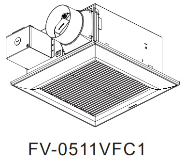
Parts Identification
FV-0511VFC1
Main Body Section

FV-0511VFC1
Main PCB Section

Main Label

FV-0511VFC1
Packing Section

Wiring Diagram


Parts List
FV-0511VF1
Main Body Section
| No. | Part No. | Part Name | Q’ty | Remark |
| 1 | FFV511VF1900 | Frame Assembly | 1 | |
| 2 | FFV511FC1910 | Adapter Assembly | 1 | |
| 3 | FFV08VKS3M915 | Connector Plate | 1 | |
| 4 | FFV511FC1301 | Connector Assy (V) | 1 | |
| 5 | FFV3450010S | Earth Lead wire | 1 | |
| 6 | FFV2800027S | Junction Cover | 1 | |
| 7 | FFV511VF1M2 | Motor | 1 | |
| 8 | FFV511VF1904 | Motor Support | 1 | |
| 9 | FFV511VF1802 | Blade | 1 | |
| 10 | FFV0511VFC1 | Main PCB Section | 1 | |
| 11 | FFV7020021S | Nut | 1 | |
| 12 | FFV511VF1906 | Casing section | 1 | |
| 13 | FFV3400146S | Grill Assembly | 1 | |
| A | FFVXTT4-8FFJ | Screw (ST4-8) | 7 | |
| B | FFVXYM4DC8BN | Screw w/washer(M4-8) | 1 | |
| C | FFV7000089S | Screw (ST4-12) | 7 |
Main PCB Section
No. |
Part No. | Part Name | Q’ty | Remark |
| 14 | FFV510SCL996 | Main PCB Box | 1 | |
| 15 | FFV510VS1M9 | Speed Switch | 1 | |
| 16 | FFV510SCL99 | Rotation Switch | 1 | |
| 17 | FFV510SCL97 | Main PCB Cover | 1 | |
| 18 | FFV511VF1321 | Motor Lead Wire | 1 | |
| 19 | FFV511FC1625 | H. Sensor Wire | 1 | |
| D | FFVXTN268GFJ | Screw | 2 |
Main Label
No. |
Part No. | Part Name | Q’ty | Remark |
| 20 | FFV51VHL1051 | Instruction Label | 1 | |
| 21 | FFV0810011S | Caution Label | 1 | |
| 22 | FFV2260003S | Holograph label | 1 | |
| 23 | FFV511FC1050 | Name Plate | 1 | |
| 24 | FFV511FC1013 | Switch Label | 1 |
Packing Section
No. |
Part No. | Part Name | Q’ty | Remark |
| 25 | FFV11QCL1920 | Hanger Assy | 1 | |
| 26 | FFV511VF1450 | Louver Pad Assy | 1 | |
| 27 | FFV4650016S | PolyCover with Print | 1 | |
| 28 | FFV511VF1891 | Top Pad | 1 | |
| 29 | FFV511VF1922 | Adapter Connector | 1 | |
| 30 | FFV511VF1892 | Bottom Pad | 1 | |
| 31 | FFV511VF1401 | Packing Case Assy | 1 | |
| 32 | FFV511VF1420 | Installation Inst (ES) | 1 | |
| 33 | FFV511VF1421 | Installation Inst (EF) | 1 | |
| 34 | FFV11KSL1M031A | Accessory A | 1 |