Mitsubishi Electric RCN-T-5AW-E2 Ceiling Cassette Wireless Control Instruction Manual


MITSUBISHI ELECTRIC RCN-T-5AW-E2 Ceiling Cassette Wireless Control

Notes:
The following functions of FDT indoor unit series are not able to be set with this wireless remote control (RCN-E2).
- Flap control system
- 4-fan speed setting (P-Hi/Hi/Me/Lo) 3-fan speed setting (Hi/Me/Lo)
Safety precautions
- Please read this manual carefully before starting installation work to install the unit properly. Every one of the followings is important information to be observed strictly.
WARNING Failure to follow these instructions properly may result in serious consequences such as death, severe injury, etc.
CAUTION Failure to follow these instructions properly may cause injury or property damage. It could have serious consequences depending on the circumstances. - The following pictograms are used in the text.
WARNING
- Consult your dealer or a professional contractor to install the unit.
- Installation work should be performed properly according to this installation manual.
- Be sure to use accessories and parts for installation work.
- Install the unit properly to a place with strength to hold the weight.
If the place is not strong enough, the unit may drop and cause injury. - Be sure to have the electrical wiring work done by electrical installer, and use exclusive circuit.
- Shut OFF the main power source before starting electrical work.
Otherwise, it could result in electric shocks, break-down or malfunction. - Do not modify the unit.
- Be sure to turn OFF the power circuit breaker before repairing/inspecting the unit.
Repairing/inspecting the unit with the power circuit breaker turned ON could cause electric shocks or injury. - Do not install the unit inappropriate environment or where gas could generate, in, accumulate or leak.
If the unit is used at places where air contains dense oil mist, steam, organic solvent vapor, corrosive gas (ammonium,
sulfuric compound, acid, etc) or where acidic or alkaline solution, special spray, etc. are used, it could cause electric rioration of its performance or corrosion. - Do not install the unit where water vapor is generated excessively or condensation occurs.
- Do not use the unit in a place where it gets wet, such as laundry room.
- Do not operate the unit with wet hands. It could cause electric shocks.
- Do not wash the unit with water. Use the cables for wiring, and connect them securely with care to protect electronic parts from external forces.
- When installing the unit at a hospital, telecommunication facility, etc., take measures to suppress electric noises. It could cause malfunction or breakdown due to hazardous effects on the inverter, private power generator, high-frequency medical equipment, radio communication equipment, etc.
- The influences transmitted from the remote control to medical or communication equipment could disrupt medical activities, video broadcasting or cause noise interference.
- Do not leave the remote control with its PCB case removed.
CAUTION
Do not install the wireless kit at the following places in order to avoid malfunction.
It could cause break-down or deformation of remote control.
- Places exposed to direct sunlight (8) Places where the receiver is influenced by
- Places near heat devices the fluorescent lamp (especially inverter
- High humidity places type) or sunlight
- Hot surface or cold surface enough to (9) Places where the receiver is affected by infrared generate condensation rays of any other communication devices
- Places exposed to oil mist or steam directly (10) Places where some object may obstruct the
- Uneven surface communication with the remote control
- Places affected by the direct air flow of the AC unit
Accessories
Please make sure that you have all of the following accessories.

Preparation before installation
Setting on site
PCB on the receiver has the following switches to set the function.
Default setting is shown with mark.
| SW1 | Prevents interference during plural setting | ON : Normal | OFF : Customized | ||
| SW2 | Receiver master/ slave setting | ON : Master | OFF : Slave | ||
| SW3 | Buzzer | ON : Valid OFF : Invalid | |||
| SW4 | Auto restart | ON : Valid | OFF : Invalid | ||
To change setting
- Remove the cover by unscrewing two screws from the back of receiver.
- Change the setting by the switch on PCB.
- When SW1 is turned to OFF position, change the wireless remote control setting.
For the method of changing the setting, refer to Setting to avoid mixed communication of - Wireless remote control .
*The receivable area of the signal refer to ⑤ Receiver .

How to install the receiver
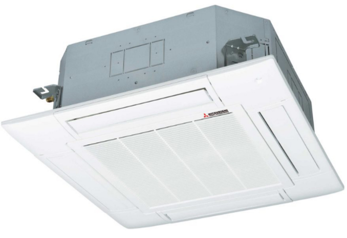
The receiver can be installed by replacing with a corner panel on the applicable decorative panel.
Installation Master/Slave setting when using plural remote controls
Preparation before installation
- Attach the decorative panel onto the air-conditioner according to the installation manual for the panel.
- Remove the air return grille.
- Remove a corner panel located on the refrigerant pipes side.
- Remove three screws and detach the cover (indicated as shadowed area) from the control box of the air- conditioner.

Installation of the receiver
- Loosen the bolts which fix the panel and make a gap between the panel and the indoor unit
- Put the wiring of the receiver through the opening.
- Put the wiring on the notch on the control box so as not to be pinched by the control box and lid as shown below.
- Connect the wiring to the terminal block provided in the control box. (No polarity)
- Attach the receiver to the panel according to the panel installation manual.
- Fix the wiring with the clamp so that the wiring do not contact the edge of control box’s metal sheet.
- Reattach the control box lid with 3 screws removed.

Wireless remote control
Installation tips for the remote control holder
Fix the remote control holder using the screws supplied with this product.
* Precautions for installing the holder
- Adjust the position so that it is upright.
- Ensure that the screw heads are not protruding.
- Do not attach the holder on plaster wall.

How to insert batteries
- Detach the back lid.
- Insert the batteries. (two AAA batteries)
- Reattach the back lid.

Setting to avoid mixed communication
- Detach the back lid, and remove the batteries.
- Cut off the switching wire in the battery compartment using nippers.
- Insert the batteries, and attach the back lid.

Changing the remote control setting
How to change the Auto Run setting The Auto Run mode is not available on the building air-conditioning and gas heat pump series (excluding the cooling/heating free multi system). When using the remote control to operate those models, set the remote control to disable the Auto Run mode.
To disable the Auto Run mode, press the ACL switch while holding down the MODE button, or insert batteries while holding down the MODE button.
* Note: Once the batteries are removed, the setting is reset to the factory default.

- How to set indoor functions
- Press the ON/OFF button to stop the unit.
- Press the desired one of the buttons shown item 2. while holding down the
FUNCTION SETTING switch. - Use the selection buttons, ▲ and ▼, to change the setting.
- Press the SET button.
The buzzer on the remote control signal receiver beeps twice, and the LED
- Setting details
The following functions can be set.Button Number indicator Function setting FAN SPEED
00 Fun speed setting : Standard 01 Fun speed setting : Setting 1 * 02 Fun speed setting : Setting 2 * MODE
00 Room heating temperature adjustment : Disable 01 Room heating temperature adjustment : +1°C 02 Room heating temperature adjustment : +2°C 03 Room heating temperature adjustment : +3°C FILTER
00 Filter sign display : OFF 01 Filter sign display : 180 hours 02 Filter sign display : 600 hours 03 Filter sign display : 1000 hours 04 Filter sign display : Operation stop after 1000 hours have elapsed U/P 00 Anti draft setting : Disable 01 Anti draft setting : Enable SILENT 00 Infrared sensor setting (Motion sensor setting) : Disable 01 Infrared sensor setting (Motion sensor setting) : Enable HI POWER
00 Infrared sensor control (Motion sensor control) : Disable 01 Infrared sensor control (Motion sensor control) : Power control only 02 Infrared sensor control (Motion sensor control) : Auto OFF only 03 Infrared sensor control (Motion sensor control) : Power control and Auto OFF ON TIMER
00 Cooling fan residual-period running : Disable 01 Cooling fan residual-period running : 0.5 hours 02 Cooling fan residual-period running : 2 hours 03 Cooling fan residual-period running : 6 hours OFF TIMER
00 Heating fan residual-period running : Disable 01 Heating fan residual-period running : 0.5 hours 02 Heating fan residual-period running : 2 hours 03 Heating fan residual-period running : 6 hours NIGHT SETBACK 00 Remote control signal receiver LED : Brightness High 01 Remote control signal receiver LED : Brightness Low 02 Remote control signal receiver LED : OFF Receiver
Control plural indoor units with one remote control
Up to 16 indoor units can be connected.- Connect the XY terminal with 2 cores wire. As for the size, refer to the following note.
- For Packaged air-conditioner series, set the indoor unit address with SW2 on the indoor unit PCB from [0] to [F] so as not to duplicate.
For the shop series
For VRF series, set the indoor unit address with SW1, SW2 and SW5-2 on the indoor unit PCB from [000] to [127] so as not to duplicate.For the building air-conditioner and gas heat pump series
Set the indoor unit and outdoor unit numbers by manually specifying the addresses.
Use the rotary switchs SW1 and SW2 provided on the indoor unit PCB (printed circuit board) to set the indoor unit numbers so that they are not duplicated.Master/Slave setting when using plural remote control
Up to two receivers can be installed in one indoor unit group.Switch Setting Function SW2
ON Master OFF Slave Wireless remote control’s operable area
Standard reachable area of the signal [condition] lluminance at the receiver: 300lux (when no liahtina is installed within 1m of the receiver in an ordinary office.)Correlation between illuminance at the receiver and reachable area of the signal in a plain view. The drawing in the right shows the correlation between the reachable area of the signal and illuminance at the receiver when the wireless remote control is operated at 1.0m high under the condition of ceiling height of 2.4m. When the illuminance becomes double, the area is narrowed down to two thirds.
Installation tips when several receivers are installed close minimum distance between the indoor units which can avoid cross communication is 5m under the condition of 300lux of illuminance at the receiver. (When no lighting is installed within 1m of the receiver in an ordinary office)
Backup switch
A Backup switch is provided on the receiver. Even when the operation from the wireless remote control is not possible (due to flat batteries, control lost, or control failure), still it possible to operate as temporary means. Press the switch directly when operating it.- The air-conditioner starts the operation with the condition of auto mode, 23°C of set point, high fan speed and horizontal louver position.
- The air-conditioner stops the operation when the switch is pressed when in operation.
Cooling test run operation
- After safety confirmation, turn on the power
- Transmit a cooling operation command with the wireless remote control unit, while the backup switch on the receiver is depressed.
- If the backup switch on the receiver is pressed during a test run, it will end the test run.
- If you cannot operate the unit properly during a test run, please check wiring by consulting with inspection guides.
How to read the 2-digit display
On the receiver of a wireless kit, a two-digit (7-segment) display is provided.- An indication will be displayed for one hour after power on.
- An indication will be displayed for 3.5 seconds after transmitting a “STOP” command from the wireless remote control or the operation of the backup switch to stop the unit.
- An indication appearing in (1) or (2) above will go off as soon as the unit starts operation.
- When there are no error records to indicate, addresses of all the connected units are displayed.
- When there are some error records remaining, the error records are displayed.
- Error records can be cleared by transmitting a “STOP” command from the wireless remote control, while the backup button is pressed.


