Panasonic PAN1781 Bluetooth Low Energy Module User Guide

Bluetooth ® Low Energy Module
Module Integration Guide
Rev. 0.2


Wireless Connectivity
PAN1781 Bluetooth Module
Overview
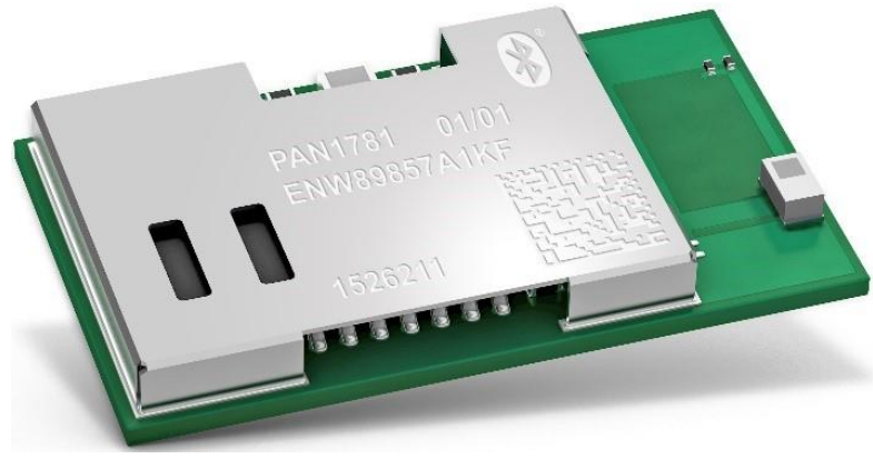
The PAN1781 is a Bluetooth 5 Low Energy (LE)
module based on the Nordic nRF52820 single chip controller.
Features
- Surface mount type dimensions: 15.6 mm × 8.7 mm × 2 mm
- Drop-in replacement for PAN1026A and PAN1762
- Nordic nRF52820 featuring ARM Cortex-M4 with 64 MHz
- Bluetooth 5 LE including LE 2M and LE Coded PHY
- Embedded 256 kB flash memory and 32 kB internal RAM
- 128-bit AES/ECB/CCM/AAR co-processor
- Up to 16 General Purpose I/O’s (GPIO), which are shared with up to 2× SPI, 2× I²C, UART, COMP, QDEC, nRESET
- USB 2.0 full-speed device interface
- Built-in temperature sensor
Bluetooth
- LE 2 Mbps high-speed PHY, LE long-range coded PHY
- LE advertising extensions (advertising on 40 channels total)
- Channel selection algorithm #2
- LE secure connections
- Angle of arrival (AoA) and angle of departure (AoD) direction finding
Characteristics
- Typical sensitivity: -95 dBm at 1 Mb/s and -103 dBm at 125 kb/s
- Typical max. output power: 8 dBm, configurable from -20 dBm in 4 dB steps and -40 dBm in whisper mode
- Typical current consumption: 4.9 mA in Tx (at 0 dBm) and 4.7 mA in Rx mode
- Typical current consumption: 0.3 µA in System OFF mode, 1.2 µA with RTC wake up
- On-module DC/DC and LDO regulators with automated low current modes
- Voltage range: 1.7 V to 5.5 V
- Temperature range: -40 °C to 85 °C
Block Diagram

By purchase of any of the products described in this document the customer accepts the document’s validity and declares their agreement and understanding of its contents and recommendations. Panasonic Industrial Devices Europe GmbH (Panasonic) reserves the right to make changes as required at any time without notification. Please consult the most recently issued Module Integration Guide before initiating or completing a design.
© Panasonic Industrial Devices Europe GmbH 2021.
This specification sheet is copyrighted. Reproduction of this document is permissible only if reproduction is without alteration and is accompanied by all associated warranties, conditions, limitations, and notices. Do not disclose it to a third party. All rights reserved.
This Module Integration Guide does not lodge the claim to be complete and free of mistakes.
Engineering Samples (ES)
If Engineering Samples are delivered to the customer, these samples have the status “Engineering Samples”. This means that the design of this product is not yet concluded. Engineering Samples may be partially or fully functional, and they may differ from the published Product Specification. Engineering Samples are not qualified and they are not to be used for reliability testing or series production.
Disclaimer
The customer acknowledges that samples may deviate from the Module Integration Guide and may bear defects due to their status of development and the lack of qualification mentioned above. Panasonic rejects any liability or product warranty for Engineering Samples. In particular, Panasonic disclaims liability for damages caused by:
- The use of the Engineering Sample other than for evaluation purposes, particularly the installation or integration in another product to be sold by the customer,
- Deviation or lapse in function of the Engineering Sample,
- Improper use of the Engineering Sample.
Panasonic Industrial Devices Europe GmbH disclaims any liability for consequential and incidental damages. In case of any queries regarding the Engineering Samples, please contact your local sales partner or the related product manager.
The information contained herein is presented only as guidance for Product use. No responsibility is assumed by Panasonic for any infringement of patents or any other intellectual property rights of third parties that may result from the use of the Product. No license to any intellectual property right is granted by this document, whether express or implied, by estoppel or otherwise.
Description of hardware, software, and other information in this document is only intended to illustrate the functionality of the referred Panasonic product. It should not be construed as guaranteeing specific functionality of the product as described or suitable for a particular application.
Any provided (source) code shall not be used or incorporated into any products or systems whose manufacture, use, or sale is prohibited under any applicable laws or regulations.
Any outlined or referenced (source) code within this document is provided on an “as is” basis without any right to technical support or updates and without warranty of any kind on a free of charge basis according to § 516 German Civil Law (BGB) including without limitation, any warranties or conditions of title, non-infringement, merchantability, or fitness for a particular purpose. The customer acknowledges that (source) code may bear defects and errors.
The third-party tools mentioned in this document are offered by independent third-party providers who are solely responsible for these products. Panasonic has no responsibility whatsoever for the performance, product descriptions, specifications, referenced content, or any and all claims or representations of these third-party providers. Panasonic makes no warranty whatsoever, neither express nor implied, with respect to the goods, the referenced contents, or any and all claims or representations of the third-party providers. To the maximum extent allowable by Law Panasonic assumes no liability whatsoever including without limitation, indirect, consequential, special, or incidental damages or loss, including without limitation loss of profits, loss of opportunities, business interruption, and loss of data.
About This Document
1.1 Purpose and Audience
This Module Integration Guide is intended to support the easy integration of the PAN1781 into a product and to ensure compliance with regulatory requirements. This guide gives an overview about the hardware design requirements by providing a reference design, which is the evaluation board of the PAN1781. It describes how to use the PAN1781 on the evaluation board with the software packages and tools provided by Nordic Semiconductors. In addition, it explains how to start up the evaluation board, get all the needed software sources, execute example code and build own implementations. It is intended for hardware design, application, and Original Equipment Manufacturers (OEM) engineers.
Please read this guide carefully to assure the compliance of your product to regulatory.
The product is referred to as “the PAN1781” or “the module” within this document.
1.2 Revision History
| Revision | Date | Modifications/Remarks |
| 0.1 | 2021-03-16 | First preliminary version |
| 0.2 | 2021-03-23 | Chapter Certification re-worked, BT-SIG Listing added |
1.3 Use of Symbols
| Symbol | Description |
| Note
Indicates important information for the proper use of the product. Non-observance can lead to errors. | |
| Attention
Indicates important notes that, if not observed, can put the product’s functionality at risk. | |
| Tip
Indicates useful information designed to facilitate working with the module and software. | |
| ⇒ [chapter number] [chapter title] |
Cross reference Indicates cross-references within the document. Example: Description of the symbols used in this document ⇒ 1.3 Use of Symbols. |
| √ | Requirement
Indicates a requirement that must be met before the corresponding tasks can be completed. |


| Symbol | Description |
| → | Result Indicates the result of a task or the result of a series of tasks. |
| This font | GUI text Indicates fixed terms and text of the graphical user interface. Example: Click Save. |
| Menu > Menu item | Path Indicates a path, e.g. to access a dialog. Example: In the menu, select File > Setup page. |
| This font | File names, messages, user input Indicates file names or messages and information displayed on the screen or to be selected or entered by the user. Examples: pan1760.c contains the actual module initialization. The message Failed to save your data is displayed. Enter the value Product 123. |
| Key | Key Indicates a key on the keyboard, e.g. F10. |
1.4 Related Documents
For related documents please refer to the Panasonic website ⇒6.2 Product Information.
Overview
The PAN1781 is a Bluetooth 5 Low Energy (LE) module based on the Nordic nRF52820 single-chip controller.
The Bluetooth 5 features additionally a higher symbol rate of 2 Mbps using the high-speed LE 2M PHY or a significantly longer range using the LE coded PHY at 500 kb/s or 125 kb/s. The new channel selection algorithm (CSA#2) improves the performance in high interference environments. Furthermore, the new LE advertising extensions allow for much larger amounts of data to be broadcasted in connectionless scenarios.
An output power of up to 8 dBm and the high sensitivity of the nRF52820 in combination with the LE coded PHY make the module very attractive in applications, where a long-range is required.
In addition, the ultra-low current consumption of the PAN1781 makes the module an ideal choice for battery-powered devices.
With the Cortex® M4 processor, 32 kB RAM, and the built-in 256 kB flash memory, the PAN1781 can easily be used in standalone mode, thereby eliminating the need for an external processor, saving complexity, space, and cost.
The PAN1781 also supports angle of arrival (AoA) and angle of departure (AoD) direction finding using Bluetooth.
A 128-bit AES/ECB/CCM/AAR co-processor may be used for on-the-fly packet encryption.
For related documents please refer to ⇒6.2 Product Information.
PAN1781 Module
3.1 Block Diagram

3.2 Footprint
Top View

3.3 Placement
Do not place any ground plane under the marked restricted antenna area in any layer! This would be affecting the performance of the chip antenna in a critical manner.
The placement of the module, surrounding material, and customer components have an impact on the radiation pattern of the antenna.

The following requirements must be met:
✓ The supply voltage must be free of AC ripple voltage (for example from a battery or a low noise regulator output). For noisy supply voltages, provide a decoupling circuit (for example a ferrite in series connection and a bypass capacitor to the ground of at least 47 µF directly at the module).
✓ This module should not be mechanically stressed when installed.
✓ Keep this module away from heat. Heat is the major cause of decreasing the lifetime of these modules.
✓ Avoid assembly and use of the target equipment in conditions where the module temperature may exceed the maximum tolerance.
✓ Keep this module away from other high-frequency circuits.
✓ Refer to the recommended pattern when designing aboard.
The antenna requires a cutout area of 5 mm x 3 mm under the PAN1781 module. This “Keep out Area” shall be located in every layer under the module antenna. Note for example the “Keep out Area” in all four layers of the PAN1781 evaluation board.
It is recommended to verify the perfect position of the module in the target application before fixing the design.
It is recommended to place the module:
- In the center (horizontal) of mother PCB.
- At the edge (horizontal) of mother PCB.
Antenna Placement Recommendation

Regulatory and Certification Information
4.1 General Certification Information
- Nordic Soft Devices S112, S113 or S140
- Bluetooth Specification 5
For further certification requests for other radio software please contact Panasonic ⇒6 Contact Details.
4.2 Federal Communications Commission (FCC) for US
4.2.1 FCC Statement
The following FCC statement has to be printed in the OEM end product user information:
The device meets the requirements for modular transmitter approval as detailed in FCC public Notice DA00-1407. The transmitter operation is subject to the following two conditions:
- This device may not cause harmful interference, and
- This device must accept any interference received, including interference that may cause undesired operation.
4.2.2 Caution
The following FCC caution has to be printed in the OEM end product user information:
These limits are designed to provide reasonable protection against harmful interference in a residential installation. This equipment generates uses and can radiate radio frequency energy and, if not installed and used in accordance with the instructions, may cause harmful interference to radio communications.
However, there is no guarantee that interference will not occur in a particular installation. If this equipment does cause harmful interference to radio or television reception (which can be determined by turning the equipment off and on) the user is encouraged to try to correct the interference by one or more of the following measures:
- Reorient or relocate the receiving antenna,
- Increase the separation between the equipment and receiver,
- Connect the equipment into an outlet on a circuit different from that to which the receiver is connected,
- Consult the dealer or an experienced radio/TV technician for help.
4.2.3 Label Requirements
The following labelling requirements have to be implemented on the OEM end product:
The FCC identifier is FCC ID: T7V1781.
This FCC identifier is valid for the PAN1781.
The end product must in any case be labelled on the exterior with:
“Contains FCC ID: T7V1781”
Due to the PAN1781 model size, the FCC identifier is displayed in the installation instruction only and it cannot be displayed readable on the module’s label due to the limited size.
4.2.4 Antenna Warning
The following Antenna has to be followed by the OEM:
This antenna warning refers to the device with the model number PAN1781.
The device is tested with an integrated antenna listed below. When integrated into the OEM’s product, these fixed antennas require installation preventing end-users from replacing them with non-approved antennas. Any antenna not in the following table must be tested to comply with FCC Section 15.203 for unique antenna connectors and with Section 15.247 for emissions.
4.2.5 Approved Antenna List
| Item | Part Number | Manufacturer | Frequency Band | Type | Max. Gain (dBi) |
| 1 | ANT016008LCS2442MA1 | TDK | 2.4 GHz | Chip Antenna | -1.0 |
4.2.6 RF Exposure
To comply with FCC RF Exposure requirements, the OEM must ensure that only antennas from the Approved Antenna List are installed ⇒4.2.5 Approved Antenna List. The preceding statement must be included as a “CAUTION” statement in manuals for products operating with the approved antennas to alert users onFCC RF Exposure compliance.
Any notification to the end-user of installation or removal instructions about the integrated radio module is not allowed.
The radiated output power of the PAN1781 with a mounted ceramic antenna (FCC ID: T7V1781) is below the FCC radio frequency exposure limits. Nevertheless, the PAN1781 shall be used in such a manner that the potential for human contact during normal operation is minimized.
End users may not be provided with the module installation instructions. OEM integrators and end users must be provided with transmitter operating conditions for satisfying RF exposure compliance.
4.3 Innovation, Science, and Economic Development (ISED) for Canada
The following IC rules have to be followed by end product OEM’s:
The PAN1781 is licensed to meet the regulatory requirements of ISED.
License ID: IC: 216Q-1781
HVIN: ENW89857A1KF, ENW89857A2KF
Manufacturers of mobile, fixed, or portable devices incorporating this module are advised to clarify any regulatory questions and ensure compliance for SAR and/or RF exposure limits. Users can obtain Canadian information on RF exposure and compliance from www.ic.gc.ca. This device has been designed to operate with the antennas listed in the Approved Antenna List, having a maximum gain of -1.0 dBi. Antennas not included in this list or having a gain greater than -1.0 dBi are strictly prohibited from use with this device. The required antenna impedance is 50 ohms. The antenna used for this transmitter must not be co-located or operating in conjunction with any other antenna or transmitter without the need for re-assessment of conformity by ISED.
Due to the model size, the IC identifier is displayed in the installation instruction and on the package label only. It cannot be displayed readable on the module’s label due to the limited size.
If the end customer application intends to use the PAN1781 in a distance smaller 10 mm from the human body, SAR evaluation has to be repeated by the OEM.
The end customer equipment must meet the actual Safety/Health requirements according to ISED.
4.3.1 IC Notice
The following IC notice has to be printed in English and French in the OEM end product user information:
Operation is subject to the following two conditions:
- This device may not cause harmful interference, and
- This device must accept any interference received, including interference that may cause undesired operation.
4.3.2 Labeling Requirements
The following IC labelling requirements have to be followed by end product OEM’s:
The OEM must ensure that IC labelling requirements are met. This includes a clearly visible label on the outside of the OEM enclosure specifying the appropriate Panasonic IC identifier for this product as well as the IC Notice above.
The IC identifier is: IC: 216Q-1781
This IC identifier is valid for the PAN1781 module. In any case, the end product must be labelled on the exterior with:
“Contains IC: 216Q-1781”
4.4 European Conformity According to RED (2014/53/EU)
Standards
- Due to the model size, the CE marking is displayed in the installation instruction and on the package label only. It cannot be displayed according to regulation (EU) No. 765/2008 in 5 mm height on the module’s label due to the limited space.
- The end product OEM has to re-assess the conformity of the end product to EU regulations but can use the PAN1781 RED pre-assessment to shorten this procedure.
- The RED EU Type Examination Certificate No. T818833N-01-TEC issued by the Notified Body 0682 can be used for the OEM end product conformance assessment. If a Notified Body has been contracted for the end product conformity assessment, it should be noted that this EU Type Examination Certificate should be used for conformance assessment.
As a result of the OEM end product conformity assessment procedure described in 2014/53/EU
Directive and other applicable EU directives, the end customer equipment should be labeled as follows:
The end customer has to assure that the device has a distance of more than 5 mm from the human body under all circumstances.
If the end customer application intends to use the PAN1781 in a distance smaller than 5 mm from the human body, SAR evaluation has to be repeated by the OEM.
The end customer equipment must meet the actual Safety/Health requirements according to RED.
PAN1781 and its model versions in the specified reference design can be used in all countries of the European Economic Area (Member States of the EU, European Free Trade Association States [Iceland, Liechtenstein, Norway]), Monaco, San Marino, Andorra, and Turkey.
4.5 Bluetooth
For Bluetooth end products which integrate the PAN1781 the OEM needs to apply for its own end product listing (EPL) at the Bluetooth SIG. If the PAN1781 is used on more than one OEM product, costs can be saved by applying for a family EPL.

For the end product EPL the following IDs can be used in order to avoid re-testing:
| Bluetooth 5 | Declaration ID | QDID |
| Component (Tested) – Link Layer | D043345 | 136204 |
| Component (Tested) – Host Layer | D043346 | 136227 |
| Component (Tested) – RF PHY | D043344 | 137461 |
| End Product – PAN1781 Bluetooth LE LR Module | D054152 | 164160 |
Bluetooth Marks
According to the Bluetooth SIG, the PAN1781 fulfills the criteria to label your product as a Bluetooth device:

For further information please refer to the Bluetooth website www.bluetooth.com
Restricted Use
5.1 Life Support Policy
This Panasonic Industrial Devices Europe GmbH product is not designed for use in life support appliances, devices, or systems where malfunction can reasonably be expected to result in a significant personal injury to the user, or as a critical component in any life support device or system whose failure to perform can be reasonably expected to cause the failure of the life support device or system, or to affect its safety or effectiveness. Panasonic customers using or selling these products for use in such applications do so at their own risk and agree to fully indemnify Panasonic Industrial Devices Europe GmbH for any damages resulting.
5.2 Restricted End Use
This Panasonic Industrial Devices Europe GmbH product is not designed for any restricted activity that supports the development, production, handling usage, maintenance, storage, inventory, or proliferation of any weapons or military use. Transfer, export, re-export, usage, or reselling of this product to any destination, end-user, or any end-use prohibited by the European Union, United States, or any other applicable law is strictly prohibited.
Contact Details
6.1 Contact Us
Please contact your local Panasonic Sales office for details on additional product options and services:
For Panasonic Sales assistance in the EU, visit
https://eu.industrial.panasonic.com/about-us/contact-us
Email:
For Panasonic Sales assistance in North America, visit the Panasonic website “Sales & Support” to find assistance near you at
https://na.industrial.panasonic.com/distributors
Please visit the Panasonic Wireless Technical Forum to submit a question at
https://forum.na.industrial.panasonic.com
6.2 Product Information
Please refer to the Panasonic Wireless Connectivity website for further information on our products and related documents:
For complete Panasonic product details in the EU, visit
http://pideu.panasonic.de/products/wireless-modules.html
For complete Panasonic product details in North America, visit
http://www.panasonic.com/rfmodules
Module Integration Guide Rev. 0.2
