Yamaha CT-160S 16 Channel Plain Mixer Instruction Manual
YAMAHA CT-160S 16 Channel Plain Mixer Instruction Manual
Effects channel
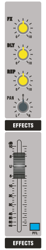
AdJusts the total volume of the effect sends bus signals sent to the console’s internal effects processor and output.

DELAY TIME SPAN OF THE EFFECTS PROCESSOR (DELAY)
Adjusts the length of the time span between each echo in the effector to simulate the reverb effects of spaces of different sizes.
REPEATS
AdJusts the times and depth of the echoes of the effector.
PAN
This has a function which distributes the signal level between left and right channels to make a stereo sound effect.
PFL
When you want to monitor echo sound & external effector sound, you can adjust this control through the headphone.
EFFECTS FADE
These are used for adjusting the volume of signal sources, which are connected to the relevant channels.
AUX / TAPE / PHONES
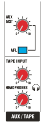
Adjusts the volume from the output jack of the AUX SEND channel in order to match the external devices.

AFL
When you want to monitor echo sound & external effector sound, you can adjust this control through the headphone.
TAPE Input Level
Adjusts the volume of a 2-track device or CD replay to the main channel L/R
PHONES LEVEL
Adjusts the volume of the monitor headphone. Use a proper volume to avoid the damage to your hearing.
Main mix & Meter
+48VDC switch supplies power to the channel’s XL input, providing power for the microphone requiring phantom power or DI-BOX. The power currents are restrictive, providing power to the XLR socket’s pin 2 and pin 3 of the mono input channel vla 6k8 ohm resistors.

Warning: When selecting phantom power, do not connect unbalanced soures or cables to the input. To avoid big clicking sound, mute the channel when turning on or off the +48V power.
Main Level Meters
In normal condition, it shows the output level of the main mix signals. When any channel’s PFL/AFL button is pressed down, it switches to show the signal level of that channel.
Working Condition Indicator
POWER: Power indicator. It lights to show working starts
PFL/AFL: Monitoring condition indicator. When the light turns on, the console is under the monitoring condition, with the main level meters showing the signal level of the monitor channel, and the channel signal is monitored from the headphone monitor output.
FADER: Adjusts the output level of the main mix, providing a normal boost from OdB to +10dB.
BLUETOOTH & MP3 PLAYER


MP3 LEVEL
Adjusts the main volume of the playing MP3 player.
PLAYER ROUTE
When the key is up, the MP3 playing signal will go directly to the main channel L/R outputs. When it’s down, the signal is sent to the CH 7/8 channel processing. At this time, the CH 7/8 channel input jack cannot be occupied. Thus, the output signal from the MP3 player can go into the CH 7/8 channel for processing and be redirected to various output ends.
Main output sections

LOUT/R OUT
The console’s main mix output is XLR & JACK. L and R output usually sends signals to the indoor PA (public address) system for live sound mixing, or to a 2-track recorder for studio mixing.
CTRL ROOM OUT
Unbalanced TRS output is post-level and post monitor-signal. These jacks are used for sending signals to the local speakers or other monitor systems.
PHONES
Unbalanced TRS jack. You can insert a headset, listening on a local monitor output. We recommend that you use closed headphones of 30 to 600 ohm impedance. Please note: Adjust the volume to avoid hearing damage
AUX SENDS OUT
Unbalanced TRS jack outputs AUX SEND AUX signals, which is for sending to monitor, effects devices such as echo and delay, and special mixing requirements.
EFFECT SEND
These are to be connected with external digital reverb &effect equipment.
EFFECT RETURN
These are to be connected with external digital reverb &effect equipment.
TAPE IN and OUT
RCA input and output connects popular recording and playing equipment, such as CD, MiniDisc, computer and cassette player. The rated line level is -2dBu. 2-track sends are normally post-fader and after LR mix, regardless of how the setting of mode switching is. 2-track returns can be used for monitoring mono or stereo recording, or serve as a simple input of replay content and background music.
Rear panel function

Power Connection and Power Switch
The pure mixer varieties use external power adaptor for power supply. Before connecting the power, make sure the power voltage of the power adaptor equipped with this console is in conformity with the local electrical voltage. When the power switch of this console is at “off ” position, all devices after this console should be at “off” position.
After you plug the power adaptor properly to the power input socket of this console, you should screw the nut going with the plug tightly and firmly. Only use the power adaptors equipped or approved by our company.
Specifications
| Maximum input level | MIC +24dBu Line +24dBu |
| Maximum output level | XLR +26dBu TRS +20dBu |
| Master meters | 10 segment -24dB to CLIP |
| Channel meters | 1 LED signal indication |
| Frequency response | 20Hz to 30KHz 0.5dB |
| CMRR (MIC 1kHz) | >75dB |
| THD+N | <0.01% (Channel to mix out) |
| Crosstalk at 1kHz | Fader shutoff >85dB Mute shutoff >85dB |
| Nolse, rms 22Hz to 22KHz | EN -122dBu Residual output noise <-90dBu |
| MONO EQ | LF, shelving, +/-15dB, 12KHZ HM, peak/dip, +/-15dB, 2.5KHz LF, shelving, +/-15dB, 80Hz |
| Mono channel | XLR balanced, pin 2 hot, 2Kohm, Sensitivity -60 to +10 dBu TRS balanced, tip hot, 10Kohm, Sensitivity -40 to+10 dBu XLR, phantom +48V |
| 2-track return | RCA, unbalanced, 4Kohm, -2 dBu |
| 2-track send | RCA, unbalanced, <75 ohm, -2 dBu |
| L/R output | XLR balanced, pin 2 hot, <75 ohm, +4 dBu, Max.+22 dBu |
| EX/AUX output | TRS unbalanced, tip hot, <75 ohm, -2 dBu, Max. +18 dBu |
| Headphones | TRS, tip L, ring R, 30 to 600 ohm headphones recommended |
| Max. Power input power | 15watts |
We are committed to continuously Improving the quality of our products. Specifications are subject to change without prior notice.
FCC Caution:
This device complies with part 15 of the FCC Rules. Operation is subject to the following two conditions: (1) This device may not cause harmful interference, and (2) this device must accept any interference received, including interference that may cause undesired operation.
Any Changes or modifications not expressly approved by the party responsible for compliance could void the user’s authority to operate the equipment.
Note: This equipment has been tested and found to comply with the limits for a Class B digital device, pursuant to part 15 of the FCC Rules. These limits are designed to provide reasonable protection against harmful interference in a residential installation. This equipment generates uses and can radiate radio frequency energy and, if not installed and used in accordance with the instructions, may cause harmful interference to radio communications. However, there is no guarantee that interference will not occur in a particular installation. If this equipment does cause harmful interference to radio or television reception, which can be determined by turning the equipment off and on, the user is encouraged to try to correct the interference by one or more of the following measures:
- Reorient or relocate the receiving antenna.
- Increase the separation between the equipment and receiver.
- Connect the equipment into an outlet on a circuit different from that to which the receiver is connected.
- Consult the dealer or an experienced radio/TV technician for help.
This equipment complies with FCC radiation exposure limits set forth for an uncontrolled environment.