LG WL1SB21 Wireless Audio Module User Manual
LG WL1SB21 Wireless Audio Module

PRODUCT NAME : Wireless audio Module
MODEL NAME : WL1SB21
| The information contained herein is the exclusive property of LG Innotek and shall not be distributed, reproduced or disclosed in whole or no in part without prior written permission of LG Innotek. |
Features
ETWADYEC02 is the small size and low power module for Wireless Audio.
ETWADYEC02 is based on Syncomm IA9QH.
- 5.2/5.8GHz GFSK Modulation
- Size : 35mm x 35mm x 5.03 mm
- Internal PCB Printed Antenna
- I2S digital audio interface
- I2C control with external device
- Low audio delay time < 20ms
- Application : Wireless Speaker, Woofer, TV Theater
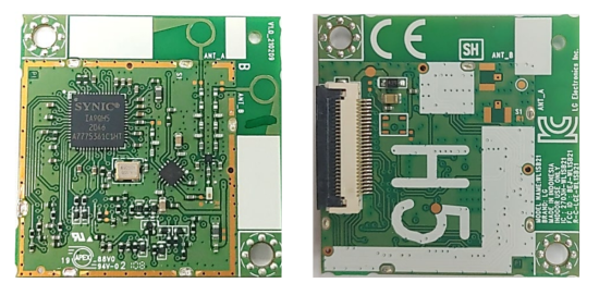
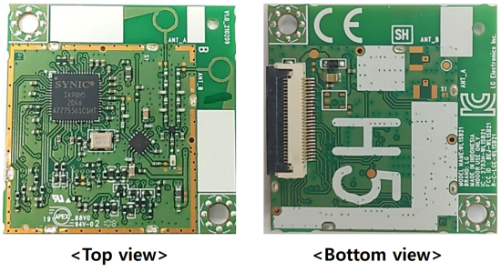
Module Photo

Block Diagram

Storage Conditions
Parameter |
Min | Max | Unit |
Storage Temperature |
-10 | +80 | ℃ |
| Storage Humidity (@ 40℃) | – | 90 | % |
Caution : The specifications above the Table define levels at which permanent damage to the device can occur. Function operation is not guaranteed under these conditions.
Operating at absolute maximum conditions for extend periods can adversely affect the long-term reliability of the device.
- Other conditions
- Do not use or store modules in the corrosive atmosphere, especially where chloride gas, sulfide gas, acid, alkali, salt or the like are contained.
Also, avoid exposure to moisture. - Store the modules where the temperature and relative humidity do not exceed 5 to 40℃ and 20 to 60%.
Operating Conditions
Parameter |
Min | Typ | Max | Unit |
Storage Temperature |
0 | – | +80 | ℃ |
| Storage Humidity (@ 40℃) | – | – | 90 | % |
Supply Voltage |
3.15 | 3.3 | 3.45 | Vdc |
Interface Specification
I2S Timing

Pin Description
| Pin No. | Pin Name | I/O | Pin Description | Pin No. | Pin Name | I/O | Pin Description |
| 1 | VCCIO | PWR | VCC supply | 14 | SPI_CLK | I/O | Clock pin of SPI interface |
| 2 | GND | GND | Ground | 15 | SPI_CS | I/O | Chip select pin of SPI interface |
| 3 | GND | GND | Ground | 16 | SPI_WP | I/O | Write protect pin of SPI interface, low active |
| 4 | BLUE_LED | I/O | GPIO | 17 | RESET | I | Reset pin, low active |
| 5 | RED_LED | I/O | GPIO | 18 | P_SENSE | I/O | GPIO |
| 6 | GND | GND | Ground | 19 | P_CTL | I/O | GPIO |
| 7 | I2S_DATA_B | I/O | Data pin of I2S signal | 20 | PWM_RST | I/O | GPIO |
| 8 | I2S_DATA_A | I/O | Data pin of I2S signal | 21 | AMP_PDN | I/O | GPIO |
| 9 | GND | GND | Ground | 22 | AMP_SD | I/O | GPIO |
| 10 | I2C_CLK | I/O | Clock pin I2C control signal | 23 | PARING_SW | I/O | GPIO |
| 11 | I2C_DATA | I/O | Data pin I2C control signal | 24 | I2S_BCK | I/O | BCK pin of I2S signal |
| 12 | SPI_DI | I/O | Data input pin of SPI interface | 25 | GNS | GND | Ground |
| 13 | SPI_DO | I/O | Data out pin of SPI interface | 26 | I2S_LRCK | I/O | LRCK pin of I2S |

Note.
- Recommend a Module install sequence for prevent operation failure – Supply 3.3V power
- Connector: 26Pin SMD Connector
Outline Drawing

Packing Information

<Regulatory notice>
FCC Statement
FCC Part 15.19 Statements:
This device complies with Part 15 of the FCC Rules. Operation is subject to the following two conditions: (1) this device may not cause harmful interference, and
(2) this device must accept any interference received, including interference that may cause undesired operation.
FCC Part 15.105 statement (Class B)
This equipment has been tested and found to comply with the limits for a Class
B digital device, pursuant to part 15 of the FCC Rules. These limits are designed to provide reasonable protection against harmful interference in a residential installation. This equipment generates, uses and can radiate radio frequency energy and, if not installed and used in accordance with the instructions, may cause harmful interference to radio communications. However, there is no guarantee that interference will not occur in a particular installation. If this equipment does cause harmful interference to radio or television reception, which can be determined by turning the equipment off and on, the user is encouraged to try to correct the interference by one or more of the following measures:
- Reorient or relocate the receiving antenna.
- Increase the separation between the equipment and receiver.
- Connect the equipment into an outlet on a circuit different from that to which the receiver is connected.
- Consult the dealer or an experienced radio/TV technician for help.
FCC Part 15.21 statement
Any changes or modifications not expressly approved by the party responsible
for compliance could void the user’s authority to operate this equipment.
Responsible Party Information
Supplier’s Declaration of Conformity47 CFR §2.1077 Compliance Information
Responsible Party –U.S. Contact Information
LG Electronics USA
1000 Sylvan Avenue Englewood Cliffs
New Jersey, United States, 07632
Telephone number or internet contact information
Regulatory notice to host manufacturer according to KDB 996369 D03 OEM Manual v01>
List of applicable FCC rules
This module has been granted modular approval as below listed FCC rule parts.
-FCC Rule parts 15C(15.407)
Summarize the specific operational use conditions
-The OEM integrator should use equivalent antennas which is the same type and equal or less gain then an antenna listed below.
RF exposure considerations
The module has been certified for integration into products only by OEM integrators under the following condition:
-The antenna(s) must be installed such that a minimum separation distance of at least 20 cm is maintained betweenthe radiator (antenna) and all persons at all times.
-The transmitter module must not be co-located or operating in conjunction with any other antenna or transmitterexcept in accordance with FCC multi-transmitter product procedures.
-Mobile use
As long as the three conditions above are met, further transmitter testing will not be required. OEM integrators should provide the minimum separation distance to end users in their end-product manuals.
Antennas list
This module is certified with the following integrated antenna.
-Type: Metal antenna (Internal Antenna)
-Max. peak Antenna gain
| Frequency Band | Ant 1 | Ant 2 |
| UNII-1 (5155-5245) | 1.47dBi | 1.36dBi |
| UNII-3 (5730-5845) | 1.39dBi | 1.45dBi |
Any new antenna type, higher gain than listed antenna should be met the requirements of FCC rule 15.203 and 2.1043 as permissive change procedure.
Label and compliance informationEnd Product Labeling The module is labeled with its own FCC ID and IC Certification Number. If the FCC ID and IC Certification Number are not visible when the module is installed inside another device, then the outside of the device into which the module is installed must also display a label referring to the enclosed module. In that case, the final end product must be labeled in a visible area with the following: “Contains FCC ID: BEJ-WL1SB21” “Contains IC: 2703H-WL1SB21 ”
Information on test modes and additional testing requirements-OEM integrator is still responsible for testing their end-product for any additional compliance requirements required with this module installed (for example, digital device emissions, PC peripheral requirements, additional transmitter in the host, etc.).
Additional testing, Part 15 Subpart B disclaimer-The final host product also requires Part 15 subpart B compliance testing with the modular transmitter installed to be properly authorized for operation as a Part 15 digital device.
ISED
RSS-GEN, Sec. 7.1.3–(licence-exempt radio apparatus)
This device complies with Industry Canada licence-exempt RSS standard(s). Operation is subject to the following two conditions:
(1) this device may not cause interference, and
(2) this device must accept any interference, including interference that may
RF Exposure The antenna (or antennas) must be installed so as to maintain at all times a distance minimum of at least 20 cm between the radiation source (antenna) and any individual.
This device may not be installed or used in conjunction with any other antenna or transmitter.
Caution: Any changes or modifications to this device not explicitly approved by manufacturer could void your authority to operate this equipment.
“The 5155-5245 MHz band is restricted to indoor use only.”
