Husqvarna 970 46 82-03 EPOS Reference Station User Manual
Husqvarna 970 46 82-03 EPOS ReferenceStation User Manual

1 Operator’s manual
1.1 Introduction
Serial number:____________________
The serial number is on the product rating plate and on the product carton. Use the serial number to register your product on www.husqvarna.com.
1.1.1 Support
For support about the product, speak to your Husqvarna servicing dealer.
1.1.2 System description
The EPOS system contains a robotic lawn mower, a charging station and a reference station. The robotic lawn mower and the reference station receives satellite signals for positioning. The reference station is stationary and sends correction data to the robotic lawn mower to get an accurate position for the mower. The work area is made virtually in an app by operating the product and adding waypoints to make a map in an app.
1.1.3 Product description
Note: Husqvarna regularly updates the appearance and function of the products. Refer to Support on page 2.
The product is a reference station that receives satellite signals and sends correction data to the mower. One reference station can be used for several robotic lawn mowers.
1.1.4 Product overview
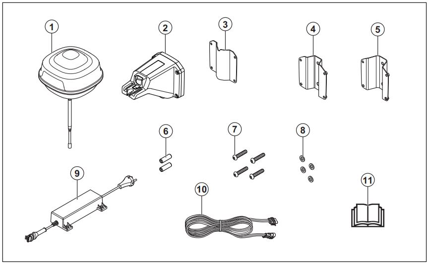

- Reference station
- Arm
- Support bracket
- Post bracket small, for post dimensions 32-44 mm/ 1.26-1.73 in.
- Post bracket large, for post dimensions 44-55 mm/ 1.73-2.16 in.
- Screws
- Screws
- Washers
- Power supply1
- Low-voltage cable
- Operator’s manual
1.1.5 Symbols on the product
These symbols can be found on the product. Make sure that you understand them.


Note: Other symbols/decals on the product refer to certification requirements for some markets.
- The appearance may differ depending on market
2 Safety
2.1 Safety definitions
Warnings, cautions and notes are used to point out specially important parts of the manual.

Note: Used to give more information that is necessary
in a given situation.
2.2 General safety instructions
- Obey national regulations about electrical safety.
- The product is only to be used with the power supply unit supplied by Husqvarna.
- The product may only be used with the equipment recommended by the manufacturer. All other types of use are incorrect. The manufacturer’s instructions with regard to operation/maintenance must be followed precisely.
- The product may only be operated, maintained and repaired by persons that are fully conversant with its special characteristics and safety regulations. Please read the Operator’s Manual carefully and make sure you understand the instructions before using the product.
- Husqvarna does not guarantee full compatibility between the product and other types of wireless systems such as remote controls, radio transmitters, hearing loops, underground electric animal fencing or similar.
- It is not permitted to modify the original design of the product. All modifications are made at your own risk.
- The operating temperature is -20°C to 45°C / -4°F to 113°F. The storage temperature is -20°C to 70°C / -4°F to 158°F.
2.3 Safety instructions for installation
- Do not put the power supply at a position where there is a risk that it can become wet. Do not put the power supply on the ground.
- Do not encapsulate the power supply. Condensed water can harm the power supply and increase the risk of electrical shock.
- Risk of Electric Shock. Install only to an residual current device (RCD) when connecting the power supply to the wall socket. Applicable to USA/ Canada. If power supply is installed outdoors: Risk of Electric Shock. Install only to a covered Class A GFCI receptacle (RCD) that has an enclosure that is weatherproof with the attachment plug cap inserted or removed.
- Make sure that the plugs of the low-voltage cable and the power supply unit are clean and dry before you connect them.
- There is a risk of falling objects during the installation of the reference station. This can result in injury.
- The power supply cable and extension cable must be outside the work area to avoid damage to the cables.
- There is a risk of falling when you install the reference station in a high position. Make sure that you have a stable position when you install the reference station.
2.4 Safety instructions for maintenance
- Disconnect the product from the power supply before you clean or do maintenance on the product.
2.5 In the event of a thunderstorm
To decrease the risk of damage to electrical components in the reference station, we recommend that the power supply to the reference station is disconnected if there is a risk of a thunderstorm. Connect the power supply again when there is no a risk of thunderstorm.
3 Installation
3.1 Introduction – Installation
Note: Refer to www.husqvarna.com for more information about installation.
3.2 To examine where to put the reference station
- Install the reference station on a fixed object that cannot move or rotate.
- Install the reference station on a post or a wall. The post must be 32-55 mm / 1.26-2.16 in. in diameter to fit the attachments on the reference station.
Note: If the reference station is installed on a wall the top of the reference station must be above the wall. There must be no metal in the wall. - The reference station needs to have full view of the sky. The sky must be visible without obscuration in all directions above 10° elevation angle.
- Install the reference station at minimum 2.5 m / 8 ft. height.
- The maximum distance between the reference station and the product is 500 m / 1640 ft. when free line of view. Objects between the reference station and product decreases the distance.
- Install the reference station where the radio signal reaches all parts of the work area. Large objects can block the radio signals.
- It is recommended to have free line of sight between product and reference station for optimal performance.
- Special settings are necessary if the site has more than one robotic lawn mower and reference station. Speak to your local Husqvarna representative for more information.

3.3 To examine where to put the power supply
- Put the power supply in an area with a roof and protection from the sun and rain.
- Put the power supply in an area with good airflow.
- Use a residual-current device (RCD) when you connect the power supply to the power outlet.
- Extend the low-voltage cable if necessary. The low-voltage cable can be extended up to 100 m / 328 ft.
3.4 Installation of the product
Read and understand the instructions about the reference station. Refer to To examine where to put the reference station on page 5.
Read the Operator’s manual for the robotic lawn mower to be used together with the reference station.
You can install the reference station on a post or a wall.
3.4.1 Installation tools
- Screwdriver, Torx 20.
- Hex key, 4 mm. Included in the carton.
3.4.2 To install the reference station on a post
- Attach the post tightly to a wall, roof top or the ground. Make sure that the post cannot move or be accidentally moved.
- Attach the support bracket and one of the post brackets to the arm with the 4 screws (4 mm hex key).
Note: The reference station must be installed at the top of the post. - Put the arm on top of the post.
Note: The reference station must be installed at the top of the post. - Attach the reference station to the post with the 2 screws (4mm hex key).
- Pull the cable on the reference station through the slot in the arm and install the reference station on the arm.
- Attach the connector to the clips on the arm.
- Tighten the screw (Torx 20) on the arm of the reference station.
- Connect the low-voltage cable to the reference station and the power supply. Refer to To examine where to put the power supply on page 5.
- Attach the low-voltage cable to the post from the reference station to the power supply with cable ties.
- Put the power supply at a minimum height of 30 cm / 12 in. from the ground.
- Connect the power supply cable to a 100-240V power outlet.
- Wait until the LED status indicator is solid green. First the LED status indicator is flashing green for some minutes. Refer to LED indicator lamp on the reference station on page 9.


3.4.3 To install the reference station on a wall
Note: As wall materials vary, screws for fixing to the wall are not included.
- Hold the arm for the reference station on the wall where you will attach it. Make 4 marks on the wall where you will attach 4 screws.
Note: If the reference station is installed on a wall the top of the reference station must be above the wall. - Drill 4 holes in the wall for the 4 screws.
- Install the reference station on the wall with 4
- Put the cable of the reference station through the slot in the arm and install the reference station on the arm.
- Attach the connector to the clips on the arm.
- Tighten the screw (Torx 20) on the arm of the reference station.
- Connect the low-voltage cable to the reference station and the power supply.
- Attach the low-voltage cable to the wall from the reference station to the power supply with cable ties.
- Put the power supply at a minimum height of 30 cm / 12 in. from the ground. Refer to To examine where to put the power supply on page 5.
- Connect the power supply cable to a 100-240V power outlet.
- Wait until the LED status indicator is solid green. First the LED status indicator is flashing green for some minutes. Refer to LED indicator lamp on the reference station on page 9.


4 Maintenance
4.1 Introduction – maintenance
Do a check of the installation each year.
- Make sure that the post is tightly attached.
- Do a check of the tightening torques for all screws.

4.2 Clean the product

5 Troubleshooting
5.1 LED indicator lamp on the reference station

6 Storage and disposal
6.1 Storage
If you store the reference station indoors, keep the arm installed at the post or wall to be able to install the reference station on its original position again.
If you keep the reference station outdoors during the winter, we recommend you to keep the power supply connected.
6.2 Disposal
Obey the local recycling requirements and applicable regulations.
7 Technical data
7.1 Technical data


7.2 Registered trademarks
The Bluetooth® word mark and logos are registered trademarks owned by Bluetooth SIG, inc. and any use of such marks by Husqvarna is under license.
8 Warranty
8.1 Warranty terms
Husqvarna® warranty covers this product’s functionality for a period of 2 years from date of purchase. The warranty covers serious faults relating to materials or manufacturing faults. Within the warranty period, we will replace the product or repair it at no charge if the following terms are met:
- The product may only be used in compliance with the instructions in this Operator’s Manual. This manufacturer’s warranty does not affect warranty entitlements against the dealer/retailer.
- End-users or non-authorized third parties must not attempt to repair the product.
Examples of faults which are not included in the warranty: - Damage caused by water seepage from using a high-pressure washer.
- Damage caused by lightning.
- Damage caused by not using Husqvarna original spare parts and accessories.
- Damage caused by non-authorized changing or tampering with the product or its power supply.
If an error occurs with your Husqvarna product, please contact Husqvarna local representative for further instructions. Please have the receipt and the product’s serial number at hand when contacting Husqvarna local representative.
9 EU Declaration of Conformity

10 UK Declaration of Conformity
We, Husqvarna AB, SE 561 82 Huskvarna, SWEDEN, Tel. +46 36 146500 declare on our sole responsibility that the product:

