Miele PFD 101 i Free Standing Dishwasher Installation Guide
Miele PFD 101 i Free Standing Dishwasher Installation Guide

Installation notes
For safe installation and commissioning of the dishwasher please read the installation plan, the service documentation, the installation sheet and the operating instructions.
This installation plan includes the dimensions of the appliance, the technical data and the requirements to be met on site for the installation of the dishwasher.
Installation requirements
This dishwasher must only be installed and commissioned by the Miele Customer Service Department, a Miele authorised dealer or a suitably qualified specialist.
Installation should only be performed in accordance with valid regulations, relevant standards and health and safety codes.
Environmental requirements
Condensate can build up in the area surrounding the dishwasher. Any
furniture and fittings in the room must therefore be suitable for purpose.
Vapour barrier film for built-in appliances
The vapour barrier film supplied protects the worktop from damage caused by steam when the door is opened. Attach the vapour barrier film above the door, underneath the worktop.
Electrical connection
All work on the electrical connection must be carried out by the Miele
Customer Service Department, an authorised Miele dealer or a qualified electrician.
Plug connection
The dishwasher should be connected to the electricity supply via a suitably rated plug and socket.
Hard-wired
If the dishwasher is hard-wired to the power supply, a power switch capable of disconnecting the dishwasher at all poles must be installed on site. This power switch must have a contact gap of at least 3 mm. The means for disconnection must be incorporated in the fixed wiring in accordance with the wiring rules AS/NZS 3000.
The socket and the power switch must be accessible after the appliance has been installed. An electrical safety test can then easily be carried out, e.g., after any service or maintenance work. The connection cable must be protected from the risk of thermal damage.
Residual current device (RCD)
For increased safety, it is recommended to protect the dishwasher with a residual current device (RCD) with a trip current of 30 mA.
Equipotential bonding
There is a screw connection point for equipotential bonding at the back of the dishwasher.
Equipotential bonding should be carried out if possible on site.
Water connection
The dishwasher must only be connected to fully vented pipework.
A brief increase in the water pressure can damage components of the dishwasher.
Water inlet
The quality of the incoming water must correspond to the drinking water specification of the country in which the dishwasher is being operated.
The dishwasher must be connected to the water supply in strict accordance with current local and national requirements (e.g. Plumbing Code of Australia (PCA)). It can be connected to cold or hot water supplies. Connecting the dishwasher to a hot water supply will reduce programme running times.
For short programme running times, dynamic water pressure of at least 200 kPa is also required.
This appliance must be installed according to AS/NZS 3500.1 and AS/NZS 3500.2. This dishwasher has been supplied with a separate backflow prevention device (dual check valve).
Installation requirements:
The dual check valve supplied separately with this product must be installed between the tap and the water inlet hose.
Screw the dual check valve onto the tap. Then screw the water inlet hose with the water protection system onto the thread of the dual check valve.
Turn on the the tap gradually to test for leaks. If there is a leak, the connection might not be on securely, or it may have been screwed on at an angle. Unscrew and reconnect the water correctly before tightening it.
If a tap is not available, only a qualified installer may connect the dishwasher to the mains water supply.
The tap should remain accessible once the dishwasher has been installed so that the water supply can be shut off whenever the appliance is not in use.
Drain
The dishwasher drain hose should be connected to a separate on-site drainage system for the dishwasher only. If a separate connection is not available, we recommend connecting the hose to a dual-chamber siphon.
If the hose is to be fitted directly to the drainage system on site, use the hose clip supplied with the dishwasher.
The on-site connector for the drain hose can be adapted to different hose diameters. If the connector extends more than 30 mm into the drain hose, it must be shortened. Otherwise, the drain hose can become blocked.
Lay the drain hose so that it does not kink and is not being subjected to pressure or tension.
If the on-site drain connection is situated lower than the guide path for the lower basket rollers in the open door, a siphoning effect during a programme can cause the wash cabinet to empty itself of water.
In this case, lay the drain hose with a bend in it so that its highest point is at least level with the guide path for the lower basket rollers.
External dispensing
An external dispensing module for liquid cleaning agents can be connected to the back of the dishwasher.
The dispensing module is available as an optional accessory and is supplied with installation instructions.
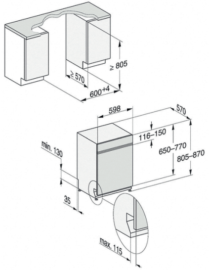
Appliance dimensions and installation dimensions
PFD 101 i

Front panel dimensions PFD 101 i
| Length | [mm] | 500–654 |
| Thickness | [mm] | 16–20 |
| Weight | [kg] | 4–11 |
Connections on the back of the appliance

On-site connections

- Electrical connection
- External dispensing, power supply connection
Equipotential bonding - Waste water
- Cold or hot water
- External dispensing, connection for dispensing hose sealed with a blind stopper*
the dispenser connector is supplied with the dispensing module
Connections
External dispensing

| Max. delivery head | [m] | 1.5 |
| Length of dispenser hose, DOS module to suction lance | [m] | 1.8 |
| Length of dispenser hose, back of appliance to DOS module | [m] | 2.8 |
| Length of power cable, back of appliance to DOS module | [m] | 2.8 |
Technical data
Dimensions and weights
| Height | [mm] | 805 |
| Height adjustment | [mm] | 65 |
| Width | [mm] | 598 |
| Depth | [mm] | 570 |
| Depth with door open | [mm] | 1165 |
| Max. plinth return | [mm] | 115 |
| Weight | [kg] | 42 |
| Max. floor load | [N] | 1000 |
Emission levels
| Sound power level | [dB(A) re 1 pW] | 46 |
| Sound pressure level in the workplace | [dB(A)] | 34.1 |
Electrical connection
Standard electrical connection
| Voltage | AC 230 V | |
| Frequency | [Hz] | 50 |
| Fuse rating | [A] | 10 |
| Plug | Yes | |
| Power cable length | [m] | 1.7 |
| Power cable cross-section | [mm2 ] | 3×1 |
| Heat output | [kW] | 1.9 |
| Total rated load | [kW] | 2.1 |
Possible voltage variant
| Voltage | 3N AC 400 V | |
| Frequency | [Hz] | 50 |
| Fuse rating | A] | 16 |
| Plug | – | |
| Power cable * length | [m] | 1.7 |
| Power cable cross-section | [mm2 ] | 5×2.5 |
| Heat output | [kW] | 7.1 |
| Total rated load | [kW] | 7.3 |
Optional accessory
Water inlet
| Max. water temperature | [°C] | 60 |
| Max. water hardness | [mmol/l] | 6.5 |
| Max. water hardness | [°dH] | 36 |
| Water connection pressure | [kPa] | 50–1000 |
| On-site threaded union (flat seal) | [inches] | ¾ |
| Connection hose length | [m] | 1.5 |
Drain
| Max. water temperature | [°C] | 82 |
| Drain hose length | [m] | 1.5 |
| Max. drain hose length | [m] | 4 |
| Max. delivery head | [m] | 1 |
| Max. transient flow rate | [l/min] | 10 |
| Hose inner diameter | [mm] | 22 |
| On-site hose sleeve ( ø x length) | [mm] | 22 x 30 |
Operating conditions
| Ambient temperature | [°C] | +5 – +40 |
| Relative humidity: Up to 31 °C, maximum Linear decreasing to 40 °C |
[%] [%] |
80 50 |
| Max. altitude above sea level up to | [m] | 4000 |
Storage and transportation conditions
| Ambient temperature | [°C] | -20 – +60 |
| Relative humidity | [%] | 10–85 |
| Air pressure | [hPa] | 500–1060 |
Min. site access dimensions including transport pallet
| Height | [mm] | 970 |
| Width | [mm] | 670 |
| Depth | [mm] | 670 |
Miele Australia Pty. Ltd.
ACN 005 635 398
ABN 96 005 635 398
1 Gilbert Park Drive
Knoxfield, VIC 3180
Telephone: 1300 731 411
Miele New Zealand Limited
IRD 98 463 631
8 College Hill
Freemans Bay
Auckland 1011
New Zealand
Telephone:
www.miele.com.au/professional
Carl-Miele-Straße 29, 33332 Gütersloh, Germany
