Makita DUX60 Cordless Multi Function Power Head Instruction Manual
makita DUX60 Cordless Multi Function Power Head Instruction Manual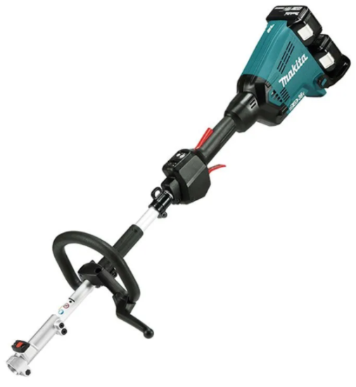

SPECIFICATIONS
| Model: | DUX60 | |
| No load speed (without attachment) | Low | 0 – 5,700 min-1 |
| Medium | 0 – 8,200 min-1 | |
| High | 0 – 9,700 min-1 | |
| Overall length | 1,011 mm | |
| Rated voltage | D.C. 36 V | |
| Net weight | 5.1 kg – 11.7 kg | |
- Due to our continuing program of research and development, the specifications herein are subject to change without notice.
- Specifications may differ from country to country.
- The weight may differ depending on the attachment(s), including the battery cartridge. The lightest and heaviest combination, according to EPTA-Procedure 01/2014, are shown in the table.
Applicable battery cartridge and charger
| Battery cartridge | BL1815N / BL1820B / BL1830B / BL1840B / BL1850B / BL1860B |
| Charger | DC18RC / DC18RD / DC18RE / DC18SD / DC18SE / DC18SF / DC18SH |
Some of the battery cartridges and chargers listed above may not be available depending on your region of residence.
WARNING: Only use the battery cartridges and chargers listed above. Use of any other battery cartridges and chargers may cause injury and/or fire.
Recommended cord connected power source
| Cord connected battery pack | BL36120A |
| Portable power pack | PDC01 / PDC1200 |
- The cord connected power source(s) listed above may not be available depending on your region of residence.
- Before using the cord connected power source, read instruction and cautionary markings on them.
No load speed with attachment
| Model | Rotation speed | |||
| Low | Medium | High | ||
| EM401MP / EM403MP | 0 – 4,200 min-1 | 0 – 6,000 min-1 | 0 – 7,100 min-1 | |
| EM406MP | 0 – 3,500 min-1 | 0 – 5,000 min-1 | 0 – 6,000 min-1 | |
| EM407MP | Upper blade | 0 – 220 min-1 | 0 – 310 min-1 | 0 – 370 min-1 |
| Lower blade | 0 – 470 min-1 | 0 – 670 min-1 | 0 – 790 min-1 | |
| EM408MP / EM409MP | 0 – 4,200 min-1 | 0 – 6,000 min-1 | 0 – 7,100 min-1 | |
| EN401MP / EN410MP / EN420MP (Strokes per minute) |
0 – 2,400 min-1 | 0 – 3,400 min-1 | 0 – 4,000 min-1 | |
| EY401MP (chain speed) | 0 – 12 m/s | 0 – 17 m/s | 0 – 20 m/s | |
| EY403MP (chain speed) | 0 – 11 m/s | 0 – 16 m/s | 0 – 19 m/s | |
| KR400MP | 0 – 160 min-1 | 0 – 230 min-1 | 0 – 280 min-1 | |
| KR401MP | 0 – 130 min-1 | 0 – 190 min-1 | 0 – 230 min-1 | |
| EE400MP | 0 – 2,800 min-1 | 0 – 4,000 min-1 | 0 – 4,700 min-1 | |
| EJ400MP | 0 – 1,600 min-1 | 0 – 2,300 min-1 | 0 – 2,800 min-1 | |
| BR400MP | 0 – 130 min-1 | 0 – 190 min-1 | 0 – 230 min-1 | |
| SW400MP | 0 – 130 min-1 | 0 – 190 min-1 | 0 – 230 min-1 | |
| UB400MP | 0 – 5,700 min-1 | 0 – 7,850 min-1 | 0 – 8,250 min-1 | |
| UB401MP | 0 – 5,700 min-1 | 0 – 7,850 min-1 | 0 – 8,250 min-1 | |
Approved attachment
| Type | Model |
| Brushcutter attachment | EM401MP / EM403MP |
| String trimmer attachment | EM406MP |
| Rotary scissors attachment | EM407MP |
| Grass trimmer attachment | EM408MP / EM409MP |
| Hedge trimmer attachment | EN401MP / EN410MP |
| Ground trimmer attachment | EN420MP |
| Pole saw attachment | EY401MP / EY403MP |
| Cultivator attachment | KR400MP / KR401MP |
| Edger attachment | EE400MP |
| Coffee harvester attachment | EJ400MP |
| Shaft extension attachment | LE400MP |
| Power brush attachment | BR400MP |
| Power sweep attachment | SW400MP |
| Blower attachment | UB400MP / UB401MP |
Symbols
The followings show the symbols which may be used for the equipment. Be sure that you understand their meaning before use.


Only for EU countries
Do not dispose of electrical and electronic appliances or batteries with household waste!

In accordance with the European Directive on waste electrical and electronic equipment and on accumulators and batteries and waste accumulators and batteries, as well as their adaptation to national law, waste electrical equipment, batteries and accumulators should be stored separately and delivered to a separate collection point for municipal waste, operating in accordance with the regulations on environmental protection.
This is indicated by the symbol of the crossed-out wheeled bin placed on the equipment.
Intended use
This cordless multi function power head is intended for driving an approved attachment listed in the section “SPECIFICATIONS” of this instruction manual. Never use the unit for the other purpose.
Noise
| Attachment | Sound pressure level average | Sound power level average | Applicable standard | |||
| L pA (dB (A)) | Uncertainty K (dB (A)) | L WA (dB (A)) | Uncertainty K (dB (A)) | |||
| EM401MP (as a brushcutter) | 78.5 | 1.0 | 90.2 | 1.5 | EN11806 | |
| EM401MP (as a string trimmer) | 84.3 | 0.6 | 93.3 | 1.6 | EN50636-2-91 | |
| EM403MP (as a string trimmer) | 84.4 | 0.4 | 98.5 | 2.3 | EN50636-2-91 | |
| EM406MP | 83.3 | 0.4 | 96.3 | 0.7 | ISO22868 (ISO11806-1)/ EN50636-2-91 | |
| EM407MP | 83.2 | 3.9 | 99.3 | 2.5 | ISO22868 (ISO11806-1) | |
| EM408MP (as a brushcutter) | 79.9 | 2.6 | 94.5 | 2.0 | ISO22868 (ISO11806-1) | |
| EM408MP (as a string trimmer) | Nylon cutting head | 79.0 | 2.6 | 91.8 | 1.7 | ISO22868 (ISO11806-1)/ EN50636-2-91 |
| Plastic blade | 80.1 | 0.7 | 91.0 | 1.6 | ISO22868 (ISO11806-1)/ EN50636-2-91 | |
| EM409MP | Nylon cutting head | 79.9 | 2.3 | 92.7 | 0.9 | ISO22868 (ISO11806-1)/ EN50636-2-91 |
| Plastic blade | 80.3 | 0.9 | 91.2 | 2.2 | ISO22868 (ISO11806-1)/ EN50636-2-91 | |
| EN401MP | 82 | 3 | 93 | 3 | EN62841-4-2 | |
| EN401MP + LE400MP | 82 | 3 | 93 | 3 | EN62841-4-2 | |
| EN410MP | 77 | 3 | 88 | 3 | EN62841-4-2 | |
| EN410MP + LE400MP | 77 | 3 | 88 | 3 | EN62841-4-2 | |
| EN420MP | 83 | 3 | 94 | 3 | EN62841-4-2 | |
| EY401MP | 92.5 | 1.4 | 101.9 | 1.4 | ISO11680-1 | |
| EY401MP + LE400MP | 86.6 | 1.0 | 101.2 | 1.0 | ISO11680-1 | |
| EY403MP | 93.6 | 1.9 | 101.6 | 1.5 | ISO22868 (ISO11680-1) | |
| EY403MP+LE400MP | 84.4 | 2.0 | 101.1 | 2.4 | ISO22868 (ISO11680-1) | |
| KR400MP | 76.7 | 2.2 | 84.2 | 1.0 | EN709 | |
| KR401MP | 73.1 | 1.4 | 84.2 | 1.8 | EN709 | |
| EE400MP | 74.8 | 1.5 | 88.2 | 2.6 | ISO11789 | |
| EJ400MP | 87.4 | 1.4 | 94.5 | 1.3 | ISO10517 | |
| EJ400MP + LE400MP | 85.6 | 1.0 | 95.5 | 1.3 | ISO10517 | |
| BR400MP | 79.5 | 0.9 | 89.0 | 0.7 | EN60335-2-72 | |
| SW400MP | 80.1 | 1.8 | 88.8 | 0.7 | EN60335-2-72 | |
| UB400MP | 89.8 | 0.4 | 100.4 | 0.8 | EN50636-2-100 | |
| UB401MP | 83.4 | 1.1 | 94.1 | 0.8 | EN50636-2-100 | |
Even if the sound pressure level listed above is 80 dB (A) or less, the level under working may exceed 80 dB (A). Wear ear protection.
NOTE: The declared noise emission value(s) has been measured in accordance with a standard test method and may be used for comparing one tool with another.
NOTE: The declared noise emission value(s) may also be used in a preliminary assessment of exposure.
Vibration
| Attachment | Left handle (Front grip) | Right handle (Rear grip) | Applicable standard | ||
| ah (m/s2) | Uncertainty K (m/s2) | ah (m/s2) | Uncertainty K (m/s2) | ||
| EM401MP (as a brushcutter) | 3.0 | 1.5 | 2.5 | 1.5 | EN11806 |
| EM401MP (as a string trimmer) | 5.0 | 1.5 | 2.5 | 1.5 | EN50636-2-91 |
| EM403MP (as a string trimmer) | 3.9 | 1.5 | 2.5 | 1.5 | EN50636-2-91 |
| EM406MP | 2.5 | 1.5 | 2.5 | 1.5 | ISO22867 (ISO11806-1) |
| EM407MP | 2.5 | 1.5 | 2.5 | 1.5 | ISO22867 (ISO11806-1) |
| EM408MP (as a brushcutter) | 2.5 | 1.5 | 2.5 | 1.5 | ISO22867 (ISO11806-1) |
| EM408MP (as a string trimmer) | 2.5 | 1.5 | 2.5 | 1.5 | ISO22867 (ISO11806-1) |
| EM409MP | 2.5 | 1.5 | 2.5 | 1.5 | ISO22867 (ISO11806-1) |
| EN401MP | 5.5 | 1.5 | 3.5 | 1.5 | EN62841-4-2 |
| EN401MP + LE400MP | 5.5 | 1.5 | 4.0 | 1.5 | EN62841-4-2 |
| EN410MP | 4.0 | 1.5 | 2.5 | 1.5 | EN62841-4-2 |
| EN410MP + LE400MP | 4.5 | 1.5 | 2.5 | 1.5 | EN62841-4-2 |
| EN420MP | 6.5 | 1.5 | 4.0 | 1.5 | EN62841-4-2 |
| EY401MP | 2.5 | 1.5 | 2.5 | 1.5 | ISO11680-1 |
| EY401MP + LE400MP | 5.5 | 1.5 | 2.5 | 1.5 | ISO11680-1 |
| EY403MP | 2.5 | 1.5 | 2.5 | 1.5 | ISO22867 (ISO11680-1) |
| EY403MP+LE400MP | 2.5 | 1.5 | 2.5 | 1.5 | ISO22867 (ISO11680-1) |
| KR400MP | 2.5 | 1.5 | 2.5 | 1.5 | EN709 |
| KR401MP | 2.5 | 1.5 | 2.5 | 1.5 | EN709 |
| EE400MP | 2.5 | 1.5 | 2.5 | 1.5 | ISO11789 |
| EJ400MP | 4.0 | 1.5 | 3.0 | 1.5 | ISO10517 |
| EJ400MP + LE400MP | 4.5 | 1.5 | 3.0 | 1.5 | ISO10517 |
| BR400MP | 2.5 | 1.5 | 2.5 | 1.5 | EN60335-2-72 |
| SW400MP | 2.6 | 1.5 | 2.6 | 1.5 | EN60335-2-72 |
| UB400MP | 4.5 | 2.0 | 2.5 | 1.5 | EN50636-2-100 |
| UB401MP | 3.6 | 1.7 | 2.5 | 1.5 | EN50636-2-100 |
NOTE: The declared vibration total value(s) has been measured in accordance with a standard test method and may be used for comparing one tool with another.
NOTE: The declared vibration total value(s) may also be used in a preliminary assessment of exposure.
SAFETY WARNINGS
General power tool safety warnings
Save all warnings and instructions for future reference.
The term “power tool” in the warnings refers to your mains-operated (corded) power tool or battery-operated (cordless) power tool.
Work area safety
- Keep work area clean and well lit. Cluttered or dark areas invite accidents.
- Do not operate power tools in explosive atmospheres, such as in the presence of flammable liquids, gases or dust. Power tools create sparks which may ignite the dust or fumes.
- Keep children and bystanders away while operating a power tool. Distractions can cause you to lose control.
Electrical safety
- Power tool plugs must match the outlet. Never modify the plug in any way. Do not use any adapter plugs with earthed (grounded) power tools. Unmodified plugs and matching outlets will reduce risk of electric shock.
- Avoid body contact with earthed or grounded surfaces, such as pipes, radiators, ranges and refrigerators. There is an increased risk of electric shock if your body is earthed or grounded.
- Do not expose power tools to rain or wet conditions. Water entering a power tool will increase the risk of electric shock.
- Do not abuse the cord. Never use the cord for carrying, pulling or unplugging the power tool.
Keep cord away from heat, oil, sharp edges or moving parts. Damaged or entangled cords increase the risk of electric shock. - When operating a power tool outdoors, use an extension cord suitable for outdoor use. Use of a cord suitable for outdoor use reduces the risk of electric shock.
- If operating a power tool in a damp location is unavoidable, use a residual current device (RCD) protected supply. Use of an RCD reduces the risk of electric shock.
- Power tools can produce electromagnetic fields (EMF) that are not harmful to the user.
However, users of pacemakers and other similar medical devices should contact the maker of their device and/or doctor for advice before operating this power tool.
Personal safety
- Stay alert, watch what you are doing and use common sense when operating a power tool.
Do not use a power tool while you are tired or under the influence of drugs, alcohol or medication. A moment of inattention while operating power tools may result in serious personal injury. - Use personal protective equipment. Always wear eye protection. Protective equipment such as a dust mask, non-skid safety shoes, hard hat or hearing protection used for appropriate conditions will reduce personal injuries.
- Prevent unintentional starting. Ensure the switch is in the off-position before connecting to power source and/or battery pack, picking up or carrying the tool. Carrying power tools with your finger on the switch or energising power tools that have the switch on invites accidents.
- Remove any adjusting key or wrench before turning the power tool on. A wrench or a key left attached to a rotating part of the power tool may result in personal injury.
- Do not overreach. Keep proper footing and balance at all times. This enables better control of the power tool in unexpected situations.
- Dress properly. Do not wear loose clothing or jewellery. Keep your hair and clothing away from moving parts. Loose clothes, jewellery or long hair can be caught in moving parts.
- If devices are provided for the connection of dust extraction and collection facilities, ensure these are connected and properly used. Use of dust collection can reduce dust-related hazards.
- Do not let familiarity gained from frequent use of tools allow you to become complacent and ignore tool safety principles. A careless action can cause severe injury within a fraction of a second.
- Always wear protective goggles to protect your eyes from injury when using power tools.
The goggles must comply with ANSI Z87.1 in the USA, EN 166 in Europe, or AS/NZS 1336 in Australia/New Zealand. In Australia/New Zealand, it is legally required to wear a face shield to protect your face, too.
It is an employer’s responsibility to enforce the use of appropriate safety protective equipments by the tool operators and by other persons in the immediate working area.

Power tool use and care
- Do not force the power tool. Use the correct power tool for your application. The correct power tool will do the job better and safer at the rate for which it was designed.
- Do not use the power tool if the switch does not turn it on and off. Any power tool that cannot be controlled with the switch is dangerous and must be repaired.
- Disconnect the plug from the power source and/or remove the battery pack, if detachable, from the power tool before making any adjustments, changing accessories, or storing power tools. Such preventive safety measures reduce the risk of starting the power tool accidentally.
- Store idle power tools out of the reach of children and do not allow persons unfamiliar with the power tool or these instructions to operate the power tool. Power tools are dangerous in the hands of untrained users.
- Maintain power tools and accessories. Check for misalignment or binding of moving parts, breakage of parts and any other condition that may affect the power tool’s operation. If damaged, have the power tool repaired before use.
Many accidents are caused by poorly maintained power tools. - Keep cutting tools sharp and clean. Properly maintained cutting tools with sharp cutting edges are less likely to bind and are easier to control.
- Use the power tool, accessories and tool bits etc. in accordance with these instructions, taking into account the working conditions and the work to be performed. Use of the power tool for operations different from those intended could result in a hazardous situation.
- Keep handles and grasping surfaces dry, clean and free from oil and grease. Slippery handles and grasping surfaces do not allow for safe handling and control of the tool in unexpected situations.
- When using the tool, do not wear cloth work gloves which may be entangled. The entanglement of cloth work gloves in the moving parts may result in personal injury
Battery tool use and care
- Recharge only with the charger specified by the manufacturer. A charger that is suitable for one type of battery pack may create a risk of fire when used with another battery pack.
- Use power tools only with specifically designated battery packs. Use of any other battery packs may create a risk of injury and fire.
- When battery pack is not in use, keep it away from other metal objects, like paper clips, coins, keys, nails, screws or other small metal objects, that can make a connection from one terminal to another. Shorting the battery terminals together may cause burns or a fire.
- Under abusive conditions, liquid may be ejected from the battery; avoid contact. If contact accidentally occurs, flush with water. If liquid contacts eyes, additionally seek medical help. Liquid ejected from the battery may cause irritation or burns.
- Do not use a battery pack or tool that is damaged or modified. Damaged or modified batteries may exhibit unpredictable behaviour resulting in fire, explosion or risk of injury.
- Do not expose a battery pack or tool to fire or excessive temperature. Exposure to fire or temperature above 130 °C may cause explosion.
- Follow all charging instructions and do not charge the battery pack or tool outside the temperature range specified in the instructions. Charging improperly or at temperatures outside the specified range may damage the battery and increase the risk of fire.
Service
- Have your power tool serviced by a qualified repair person using only identical replacement parts. This will ensure that the safety of the power tool is maintained.
- Never service damaged battery packs. Service of battery packs should only be performed by the manufacturer or authorized service providers.
- Follow instruction for lubricating and changing accessories.
Important safety instructions for battery cartridge
- Before using battery cartridge, read all instructions and cautionary markings on (1) battery charger, (2) battery, and (3) product using battery.
- Do not disassemble or tamper with the battery cartridge. It may result in a fire, excessive heat, or explosion.
- If operating time has become excessively shorter, stop operating immediately. It may result in a risk of overheating, possible burns and even an explosion.
- If electrolyte gets into your eyes, rinse them out with clear water and seek medical attention right away. It may result in loss of your eyesight.
- Do not short the battery cartridge:
(1) Do not touch the terminals with any conductive material.
(2) Avoid storing battery cartridge in a container with other metal objects such as nails, coins, etc.
(3) Do not expose battery cartridge to water or rain.
A battery short can cause a large current flow, overheating, possible burns and even a breakdown. - Do not store and use the tool and battery cartridge in locations where the temperature may reach or exceed 50 °C (122 °F).
- Do not incinerate the battery cartridge even if it is severely damaged or is completely worn out. The battery cartridge can explode in a fire.
- Do not nail, cut, crush, throw, drop the battery cartridge, or hit against a hard object to the battery cartridge. Such conduct may result in a fire, excessive heat, or explosion.
- Do not use a damaged battery
- The contained lithium-ion batteries are subject to the Dangerous Goods Legislation requirements.
For commercial transports e.g. by third parties, forwarding agents, special requirement on packaging and labeling must be observed.
For preparation of the item being shipped, consulting an expert for hazardous material is required.
Please also observe possibly more detailed national regulations.
Tape or mask off open contacts and pack up the battery in such a manner that it cannot move around in the packaging. - When disposing the battery cartridge, remove it from the tool and dispose of it in a safe place. Follow your local regulations relating to disposal of battery.
- Use the batteries only with the products specified by Makita. Installing the batteries to non-compliant products may result in a fire, excessive heat, explosion, or leak of electrolyte.
- If the tool is not used for a long period of time, the battery must be removed from the tool.
- During and after use, the battery cartridge may take on heat which can cause burns or low temperature burns. Pay attention to the handling of hot battery cartridges.
- Do not touch the terminal of the tool immediately after use as it may get hot enough to cause burns.
- Do not allow chips, dust, or soil stuck into the terminals, holes, and grooves of the battery cartridge. It may result in poor performance or breakdown of the tool or battery cartridge.
- Unless the tool supports the use near high-voltage electrical power lines, do not use the battery cartridge near high-voltage electrical power lines. It may result in a malfunction or breakdown of the tool or battery cartridge.
- Keep the battery away from children.
SAVE THESE INSTRUCTIONS.
PARTS DESCRIPTION

- Battery cartridge
- Lock-off lever
- Switch trigger
- Hanger
- Handle
- Release button
- Barrier (country specific)
- Speed indicator
- Power lamp
- Main power button
- Reverse button
- Shoulder harness
FUNCTIONAL DESCRIPTION
Failure to switch off and remove the battery cartridge may result in serious personal injury from accidental start-up.
Installing or removing battery cartridge

- Red indicator
- Button
- Battery cartridge
To remove the battery cartridge, slide it from the tool while sliding the button on the front of the cartridge.
To install the battery cartridge, align the tongue on the battery cartridge with the groove in the housing and slip it into place. Insert it all the way until it locks in place with a little click. If you can see the red indicator as shown in the figure, it is not locked completely.
Tool / battery protection system
The tool is equipped with a tool/battery protection system. This system automatically cuts off power to the motor to extend tool and battery life. The tool will automatically stop during operation if the tool or battery is placed under one of the following conditions:

Overload protection
If the tool is overloaded by entangled weeds or other debris,
In this situation, turn the tool off and stop the application that caused the tool to become overloaded. Then turn the tool on to restart.

Overheat protection for tool or battery
When a over heating occurs, all speed indicators blink.
If the overheating occurs, the tool stops automatically. Let the tool and/or battery cool down before turning the tool on again.
Overdischarge protection
When the battery capacity becomes low, the tool stops automatically and

If the tool does not operate even when the switches are operated, remove the batteries from the tool and charge the batteries.
Indicating the remaining battery capacity
Only for battery cartridges with the indicator
- Indicator lamps
- Check button
Press the check button on the battery cartridge to indicate the remaining battery capacity. The indicator lamps light up for a few seconds.

NOTE: Depending on the conditions of use and the ambient temperature, the indication may differ slightly from the actual capacity.
NOTE: The first (far left) indicator lamp will blink when the battery protection system works.
Main power switch
To stand by the tool, press the main power button until the main power lamp lights up. To turn off, press the main power button again.

- Main power button
NOTE: The main power lamp brinks if the switch trigger is pulled under unoperatable conditions. The lamp blinks if you turn on the main power switch while holding down the lock-off lever and the switch trigger.
NOTE: This tool employs the auto power-off function.
To avoid unintentional start up, the main power switch will automatically shut down when the switch trigger is not pulled for a certain period after the main power switch is turned on.
Switch action
NOTICE: Do not pull the switch trigger hard without pressing the lock-off lever. This can cause switch breakage.
To prevent the switch trigger from being accidentally pulled, a lock-off lever is provided.

- Lock-off lever
- Switch trigger
To start the tool, turn on the main power switch and grasp the handle (the lock-off lever is released by the grasp) and then pull the switch trigger. Tool speed is increased by increasing the pressure on the switch trigger. To stop the tool, release the switch trigger.
Speed adjusting
You can adjust the tool speed by tapping the main power button.
Each time you tap the main power button, the level of speed will change.

- Main power button

Reverse button for debris removal
Failure to switch off and remove the battery cartridge may result in serious personal injury from accidental start-up.
This tool has a reverse button to change the direction of rotation. It is only for removing weeds and debris entangled in the tool.
To reverse the rotation, tap the reverse button and pull the trigger when the tool’s head is stopped. The power lamp starts blinking, and the tool’s head rotates in reverse direction when you pull the switch trigger.
To return to regular rotation, release the trigger and wait until the tool’s head stops.
- Reverse button
NOTE: During the reverse rotation, the tool operates only for a short period of time and then automatically stops.
NOTE: Once the tool is stopped, the rotation returns to regular direction when you start the tool again.
NOTE: If you tap the reverse button while the tool’s head is still rotating, the tool comes to stop and to be ready for reverse rotation.
Electronic torque control function
The tool electronically detects a sudden drop in the rotation speed which may cause a kickback. In this situation, the tool automatically stops to prevent further rotation of cutting tool. To restart the tool, release the switch trigger. Clear the cause of sudden drop in the rotation speed and then turn the tool on.
NOTE: This function is not a preventive measure for kickbacks.
ASSEMBLY
Mounting the handle
Attach the handle with supplied clamps and bolts. Make sure that the handle is located between the spacer and the arrow mark. Do not remove or shrink the spacer.
- Handle
- Hex socket bolt
- Clamp
- Spacer
- Arrow mark
Attach the barrier (country specific) to the handle using the screw on the barrier. Once assembled, do not remove the barrier.
- Barrier
- Screw
Mounting the attachment pipe
Mount the attachment pipe to the power unit
- Turn the lever of the power unit toward the attachment side.
- Lever
- Remove the cap of the attachment. Align the pin with the arrow mark and insert the attachment pipe until the release button pops up.
- Release button
- Arrow mark
- Pin
- Turn the lever toward the power unit side.
- Lever
Make sure that the surface of the lever is parallel to the pipe.
To remove the pipe, turn the lever toward the attachment side and pull the pipe out while pressing down the release button.
- Release button
- Lever
- Pipe
Adjusting the handle/hanger position
Adjust the handle and hanger position to obtain confortable handling of the tool.
Loosen the hex socket head bolt on the handle. Move the handle to a comfortable working position and then tighten the bolt.
- Handle
- Hex socket head bolt
Loosen the hex socket head bolt on the hanger. Move the hanger to a comfortable working position and then tighten the bolt.
- Hex socket head bolt
- Hanger
Attaching shoulder harness
If you put on the shoulder harness included in the tool package and the shoulder harness of the backpack-type power supply at the same time, removing the tool or backpack-type power supply is difficult in case of an emergency, and it may cause an accident or injury. For the recommended hanging band, ask Makita Authorized Service Centers.
Put the shoulder harness on your left shoulder by putting your head and right arm through it. Keep the tool on your right side.
After putting the shoulder harness, attach it to the tool by connecting the buckles provided on both the tool hook and the harness. Be sure that the buckles click and lock completely in place. Adjust the strap to the suitable length for your operation.
- Hanger
- Hook
The buckle is provided with a means of quick release which can be accomplished by simply squeezing the sides and the buckle.
- Buckle
Hex wrench storage
When not in use, store the hex wrench as illustrated to keep it from being lost.
- Handle
- Hex wrench
MAINTENANCE
NOTICE: Never use gasoline, benzine, thinner, alcohol or the like. Discoloration, deformation or cracks may result.
Battery guard
Do not use the tool with the battery guard removed or damaged. Direct impact to the battery cartridge may cause battery malfunction and result in injury and/ or fire. If the battery guard is deformed or damaged, contact your authorized service center for repairs.
- Battery guard
To maintain product SAFETY and RELIABILITY, repairs, any other maintenance or adjustment should be performed by Makita Authorized or Factory Service Centers, always using Makita replacement parts.
TROUBLESHOOTING
Before asking for repairs, conduct your own inspection first. If you find a problem that is not explained in the manual, do not attempt to dismantle the tool. Instead, ask Makita Authorized Service Centers, always using Makita replacement parts for repairs
| State of abnormality | Probable cause (malfunction) | Remedy |
| Motor does not run. | Battery cartridge is not installed. | Install the battery cartridge. |
| Battery problem (under voltage) | Recharge the battery. If recharging is not effective, replace battery. | |
| The drive system does not work correctly. | Ask your local authorized service center for repair. | |
| Motor stops running after a little use. | Rotation is in reverse. | Change the direction of rotation with the reversing switch. |
| Battery’s charge level is low. | Recharge the battery. If recharging is not effective, replace battery. | |
| Overheating. | Stop using of tool to allow it to cool down. | |
| It does not reach maximum RPM. | Battery is installed improperly. | Install the battery cartridge as described in this manual. |
| Battery power is dropping. | Recharge the battery. If recharging is not effective, replace battery. | |
| The drive system does not work correctly. | Ask your local authorized service center for repair. |
OPTIONAL ACCESSORIES
If you need any assistance for more details regarding these accessories, ask your local Makita Service Center. Refer to “Approved attachment” section for the applicable models for this tool.
- Edger attachment
- Brushcutter attachment
- String trimmer attachment
- Rotary scissors attachment
- Grass trimmer attachment
- Hedge trimmer attachment
- Ground trimmer attachment
- Pole saw attachment
- Coffee harvester attachment
- Cultivator attachment
- Shaft extension attachment
- Power brush attachment
- Power sweep attachment
- Blower attachment
- Makita genuine battery and charger
NOTE: Some items in the list may be included in the tool package as standard accessories. They may differ from country to country.
Makita Corporation
3-11-8, Sumiyoshi-cho,
Anjo, Aichi 446-8502 Japan
www.makita.com
