Honeywell L510 Lamp Controller Instructions
Honeywell L510 Lamp Controller Instructions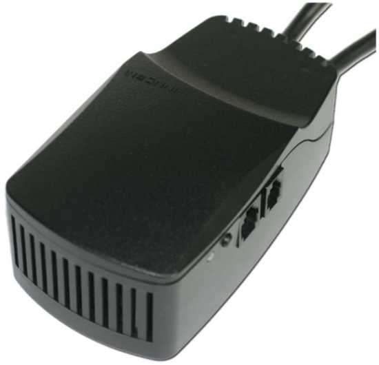

Overview
The L510 Lamp Controller is designed for the hospitality industry to provide convenient switched and dimming control of several different load types, including; incandescent, CFL and LEDs. By doing this, it converts any standard lamp into a remotely controlled lamp with the ability to create scenic and mood lighting. The L510 is able to participate in
Honeywell’s overall Energy Management System (EMS) to provide energy savings along with enhanced guest experience.
A typical application would include a L510 controlling scenic lighting around a headboard of a guestroom bed. To provide this control, the L510 is equipped with an INNCOM WBI relay, Triac or FET actuator and communicates via the on-board 2.4Ghz radio over the INNCOM DeepMesh network. The L510 which is controlling the lamp can be
controlled by an INNCOM MODEVA or EVORA switch as well as also be controlled locally. Other applications include; desk and floor lamp control as well as wall sconce control.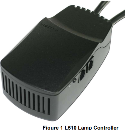

Part Numbers
PART NUMBERS: DESCRPTION
201-7050: Relay Actuator RF Lamp Controller, 120-240VAC, 500W
201-7051: Triac Dimmer RF Lamp Controller, 120VAC, 650W
201-7052: FET Dimmer RF Lamp Controller, 120VAC, 350W
System Layout


Load Ratings
| Model | Voltage | Freq | Rating Power / Amperes | Type of Load |
| 201-7050 Relay | 120-240 Vac | 50/60 Hz | 4.1 A | Resistive |
| 120-240 Vac | 50/60 Hz | 4.1 A | General Purpose | |
| 120-240 Vac | 50/60 Hz | 500 W | Tungsten / ELV | |
| 120-240 Vac | 50/60 Hz | 250 VA | Electric Ballast | |
| 120-240 Vac | 50/60 Hz | 1/10 HP | Motor | |
| 201-7051 (Triac) | 120 Vac | 60 Hz | 2.9 A | Resistive |
| 120 Vac | 60 Hz | 2.9 A | General Purpose | |
| 120 Vac | 60 Hz | 650W | Tungsten / ELV | |
| 120 Vac | 60 Hz | 250 VA | Electronic Ballast | |
| 120 Vac | 60 Hz | 1/10 HP | Motor | |
| 201-7052 (FET) | 120 Vac | 60 Hz | 2.9 A | Resistive |
| 120 Vac | 60 Hz | 2.9 A | General Purpose | |
| 120 Vac | 60 Hz | 350 W | Tungsten / ELV | |
| 120 Vac | 60 Hz | 250 VA | Electronic Ballast |
Product Specification
| Parameter | Specification | Range / Value |
| S5 Bus | Data Rate | 2550bps |
| Range | 50ft | |
| Max Nodes | 20 | |
| DeepMesh RF | Range | 70ft |
| Transmit Power | +5dBm | |
| Receive Sensitivity | -95dBm | |
| Protocol | IEEE 802.15.4 | |
| Frequency Band | 2405MHz – 2480MHz | |
| Channels | 11-26 | |
| I/O | Digital input / outputs | 2 dry contact inputs / UART pins |
| Power | Input Voltage | 120Vac |
| Device Power Consumption | 12VDC, 100mA | |
| Max DC Power | 200mA (100mA available to power external device on 12Vdc) | |
| Environment | Operating Temperature | 0 -30C |
| Storage Temperature | -10 – 50C | |
| Humidity | 10 – 90% RH, Non-condensing | |
| Approvals | CFR47 FCC Part 15.247 Subpart C | |
| CR47 FCC Part 15 Subpart B | ||
| RSS-247 Issue 2 | ||
| ICES-003 Issue 6 | ||
| RSS-Gen Issue 5 | ||
| Rss-102 Issue 5 |
RJ-12 Low Voltage Connector

RJ-9 Switch Connector
| Pin | Typical Color* | Function |
| 1 | White | GND |
| 2 | Black | +12V |
| 3 | Red | S5 Bus |
| 4 | Green | INPUT 1 / UART- Tx |
| 5 | Yellow | INPUT 2 / UART – R |
| 6 | Blue | NC |
| *Wire colors may differ | ||
RJ-9 Connector

Conformance statement
FCC ID: GTC-201705X
This device complies with part 15 of the FCC Rules. Operation is subject to the following two conditions:
- This device may not cause harmful interference, and
- this device must accept any interference received, including interference that may cause undesired operation.
CAUTION: changes or modifications not expressly approved by the party responsible for compliance could void the user’s authority to operate the equipment.
NOTE: This equipment has been tested and found to comply with the limits for a Class B digital device, pursuant to part 15 of the FCC Rules. These limits are designed to provide reasonable protection against harmful interference in a residential installation. This equipment generates, uses and can radiate radio frequency energy and, if not installed and used in accordance with the instructions, may cause harmful interference to radio communications.
However, there is no guarantee that interference will not occur in a particular installation. If this equipment does cause harmful interference to radio or television reception, which can be determined by turning the equipment off and on, the user is encouraged to try to correct the interference by one or more of the following measures:
- Reorient or relocate the receiving antenna.
- Increase the separation between the equipment and receiver.
- Connect the equipment into an outlet on a circuit different from that to which the receiver is connected.
- Consult the dealer or an experienced radio/TV technician for help.
Any changes or modifications not expressly approved by the party responsible for compliance could void the user’s authority to operate this equipment.
IC: 1609A-201705X
This device contains licence-exempt transmitter(s)/receiver(s) that comply with Innovation, Science and Economic Development Canada’s licence-exempt RSS(s). Operation is subject to the following two conditions:
- This device may not cause interference.
- This device must accept any interference, including interference that may cause undesired operation of the device.
Wiring

- Only a trained, experienced service technician should install the L510. Before beginning, the installer should check the ratings given in the instructions and on the product to make sure the product is suitable for the application.
- The installer must disconnect the AC from the drape motor power supply before beginning the installation to prevent electrical shock or equipment damage.
- All wiring must comply with local codes and ordinances.
- The L510 is intended for INDOOR USE ONLY.
- It is important to read the instructions carefully. Failure to follow them could damage the product or cause a hazardous condition.
Ordering Specifications
| Model # | Description |
| 201-7050 | L510 – Relay Lamp Controller |
| 201-7051 | L510 – Triac Lamp Controller |
| 201-7052 | L510 – FET Lamp Controller |
Document Revision History
| REVISION | DATE ISSUED | REASON |
| V0.2 | 12 -Feb-2021 | Added IC / FCC ID |