Miele PW 5105 Washer Extractor Installation Guide
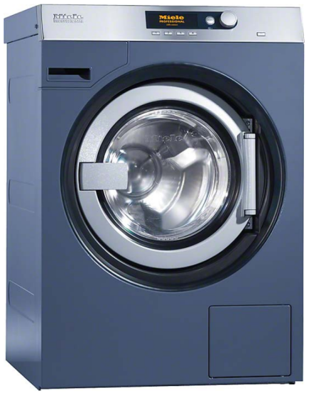
Miele PW 5105 Washer Extractor

It is essential to read the operating and installation instructions before installing, commissioning or using the machine. This avoids the risk of accidents or damage.
All rights reserved
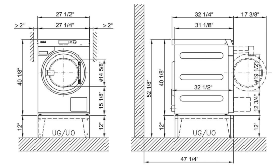
Dimensions


Technical datasheet
Washer-extractor: PW 5105 AV (Dump valve)
Heating: Electric (EL)
Legend
| Abbreviations in bold type: Connection required | |
| Abbreviations in circle with dashes: Connection optional or required depending on model version |


Optional extras
| UM | Miele base | UO 5010 (UO = open base) Height Width Depth |
12” 27” 31” |
305 mm 684 mm 787 mm |
| UG 5010 (UG = closed base) Height Width Depth |
12” 27 1/4” 31” | 305 mm 692 mm 788 mm | ||
| BS | Concrete base | Quality and density of concrete must comply with load. Concrete base must be firmly secured to floor! Recommended height Minimum height Recommended width Recommended depth |
11 13/16” 2 3/4” ≥ 27 9/16” ≥ 31 1/2” | 300 mm 70 mm ≥700 mm ≥800 mm |
| Dispensing pump | Pump installation may only be performed by Miele Service. External dispensing pumps (2 or 4 head pump): Voltage (external power supply required) Fusing Supplied with supply cable and plug |
120V 15A NEMA 5-15 |
| Electrical connection (convertible) | Standard voltage Frequency Rated load Fuse rating Length of supply lead Supplied with plug |
6.5′ | 2 AC 220 – 240V 60 Hz 4.4 – 5.2 kW 2 x 30 A 2000 mm NEMA L6-30P | |
| Convertible to Frequency Rated load Fuse rating Length of supply lead Supplied with plug |
6.5′ | 2 AC 208V 60 Hz 4.0 kW 2 x 30 A 2000 mm NEMA L6-30P | ||
| Electrical connection must comply with national regulations. Connection using multi-pole wall lockable socket in compli-ance with IEC/EN 60309 and IEC/EN 60947 is recommended in order to simplify electrical tests. If machines are hard-wired, a multi-pole mains switch must be provided on site. Switches with a contact gap of more than 3 mm can be used. These include switches, fuses and contactors (IEC/EN 60947). A wall socket or mains isolator must be easily accessible after installation. Reinstallation of the supply point, changes to the equipment or checks on the protective conductor, including determination of correct fuse rating, should only be performed by a properly trained electrician. If necessary, equipotential bonding with good galvanic contact must be provided in accordance with all appropriate national and local regulations. | ||||
| Cold water (Soft water) |
Min. flow pressure Max. pressure Max. throughput On-site connection thread Length of connection hose (supplied: 1 connection hose) Hourly water demand (average for 60°C program) for standard connection (with warm and cold water) If warm water supply is not available add warm water demand to cold water demand. |
14.5 psi 145 psi 2.9 gal/min 3/4″ garden hose thread, male 61” approx. 18.5 gal/h |
100 kPa 1000 kPa 11 l/min | |
| Warm water
(Soft water) |
Max. temperature Min. flow pressure Max. pressure Max. throughput On-site connection thread Length of connection hose (supplied: 1 connection hose) Hourly water demand (average for 60°C program) If reprogrammed by Miele Service, the Machine can also be connected to a hot water supply line with a temperature of 70°C to max. 85°C. This requires a separate inlet hose. This additional inlet hose is available from Miele Spares. If warm water is not available, connect warm water hose to cold water valve! |
158°F 14.5 psi 145 psi 2.9 gal/min 3/4″ garden hose thread, male 61” approx. 18.5 gal/h |
70°C 100 kPa 1000 kPa 11 l/min 3/4″ garden hose thread, male 1550 mm approx. 70 l/h | |
| Drain: Dump valve | Max. temperature Machine-side drain connection (ext. diameter) On-site drain (int. diameter) Max. transient throughput Vented drainage required. If ventilation is insufficient, fit Miele kit, Mat. no. 05238090. Drain manifolds serving several machines must be of sufficient cross-section. |
158°F 2 15/16” 2 15/16” 16.4 gal/min |
70°C 75 [DN 70] mm 75 [DN 70] mm 62 l/min | |
| Fittings for base/floor installation | Miele base UG/UO 5010
4 × metal angled brackets (to secure machine to base ) |
5/16” x 2 9/16” 1/2” x 2 3/8” |
8 mm x 65 mm 12 mm x 60 mm | |
| Installation on floor or concrete base 2 × clamps 2 × screws DIN 571 (Ø × length) 2 × rawl plugs (Ø × length) Machine must be bolted to the base or floor. Fittings are supplied with machine Fixing materials for a floating screed floor are to be provided on site. |
1/2” x 2”5/16” x 1 9/16” | 6 mm x 50 mm 8 mm x 40 mm | ||


| Machine data | Unit width | 27 9/16” | 700 mm | |
| Machine depth | 32 9/16” | 827 mm | ||
| Unit height | 40 3/16” | 1020 mm | ||
| Casing width | 31 3/16” | 792 mm | ||
| Casing depth | 31 1/8” | 790 mm | ||
| Minimum width of delivery access to installation site | 28 3/8” | 720 mm | ||
| Recommended rear wall gap (measured to front of machine) | 47 1/4” | 1200 mm | ||
| Minimum rear wall gap (to front of machine) | 39 3/8” | 1000 mm | ||
| Recommended rear wall gap ensures sufficient space for | ||||
| maintenance and servicing. | ||||
| Net weight | 327 lbs | 148 kg | ||
| Dynamic floor load, max. | 2750 N | 2750 N | ||
| Static floor load, max. | 1960 N | 1960 N | ||
| Dynamic load, max. | 790 N | 790 N | ||
| Drum frequency, max. | 18 Hz | 18 Hz | ||
| Average heat dissipation | 2630 BTU/hr | 0.77kWh | ||
| (dependent on ambient room temperature and program | ||||
| selected) | ||||
| Sound pressure (re 20 mPA), | <70 dB (A) | <70 dB (A) | ||
| workplace-related (at distance of 1 m and height of 1.6 m) | ||||
| Installation should only be carried out by authorized installers in accordance with valid regulations! Follow installation instructions when installing machine! All rights reserved! | ||||
Technical datasheet: PW5105 EL AV (Dump valve)

Was this manual helpful?
Thank you for your feedback!