Panasonic FV-0510VSC1 Ventilating Fan Instruction Manual


Installation and Operating
Instructions Ventilating Fan
Model No. FV-0510VSC1
FV-0810VSS1

READ AND SAVE THESE INSTRUCTIONS
Thank you for purchasing this Panasonic product.
Please read these instructions carefully before attempting to install, operate or service the Panasonic product. Please carefully read the “GENERAL SAFETY INFORMATION” (P.2-4) of this manual before use. Failure to comply with instructions could result in personal injury or property damage. Please explain to users how to operate and maintain the product after installation, and this booklet should be presented to users. Please retain this booklet for future reference.
GENERAL SAFETY INFORMATION
For Your Safety
To reduce the risk of injury, loss of life, electric shock, fire, malfunction, and damage to equipment or property, always observe the following safety precautions.
Explanation of symbol word panels
The following symbol word panels are used to classify and describe the level of hazard, injury, and property damage caused when the denotation is disregarded and improper
use is performed.
NOTICE Denotes a hazard that could result in property damage.
The following symbols are used to classify and describe the type of instructions to be observed.

TO REDUCE THE RISK OF FIRE, ELECTRIC SHOCK, OR INJURY TO PERSONS, OBSERVE THE FOLLOWING:


GENERAL SAFETY INFORMATION

GENERAL SAFETY INFORMATION
NOTICE

DESCRIPTION
These products are listed by UL under UL file No. E78414. These products use a sirocco fan driven by a DC motor powered by an integral transformer. The motor is designed to have long operating life, high dynamic response, higher speed ranges with saving energy. The grille covering the fan body is a spring-loaded, quick remove type. A damper for preventing air counterflow is provided. The blower uses a high-capacity sirocco fan developed to reduce the noise level.
UNPACKING
Unpack and carefully remove the product from the carton. Refer to the supplied accessories list to verify that all parts are present.
SUPPLIED ACCESSORIES
| Part name | Appearance | Quantity |
| Grille | 1 | |
| Long screw (ST4.2X30) | 5 (1 for spare) | |
| Installation and operating instructions | 2 | |
| Limited warranty | 1 |


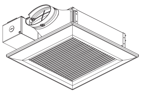
DIMENSIONS

| No. | Part name |
| 1 | PCB box |
| 2 | Blower assy |
| 3 | Blade |
| 4 | Pick-A-Flow switch |
| 5 | Multi-Speed switch (FV-0810VSS1 only) |
| Induction humidity setting switch (FV-0510VSC1 only) | |
| 6 | Condensation sensor (FV-0510VSC1 only) |
| 7 | Grille |
| 8 | Adaptor |
| 9 | Junction box |
| 10 | Connector plate |
| 11 | Damper |
| 12 | © Suspension |
| 13 | Fan body |
WIRING DIAGRAM

These products employ innovative, state-of-the-art technologies that provide a number of customizable unique features that lead to improved indoor air quality. Please read this manual first in order to realize the benefits of this customizable, modular fan.
Optimum ventilation performance:
Duct length, elbows, and other factors increase static pressure which can hinder the performance of most ventilation fans. These products utilize SmartFlow microchip technology that monitors the static pressure in the system and speeds up or slows down the rpm of the fan depending upon the amount of resistance within the ducts. This feature allows the fan to perform as rated and avoid potential installation issues.
Outstanding energy savings:
These products are built using DC motor technology. The DC motor is 30 %-70 % more energy efficient than the minimum ENERGY STAR requirements. [For model: FV-0810VSS1] This product can set the high air volume by Pick-A-Flow switch, and set the low air volume by Multi-speed switch, and operate as below.

Note:

- The product will also run when the environment’s humidity rise rapidly but does not reach the humidity setting, and stop after delayed operation.
- Induction humidity setting switch is stepless change between 30 %RH-80 %RH.
- The humidity detected by the sensor may differ from the value on your hygrometer.
- The product may be on and off caused by the unstable environment humidity, you can improve it by adjusting the Induction humidity setting switch.
PLEASE READ PRIOR TO INSTALLATION
[For model: FV-0810VSS1]
Spot and continuous ventilation: This product is designed to run continuously ensuring a the healthy environment at low airflow levels 24 hours a day. By utilizing the CustomVent Multi-speed module the product is built to run continuously at a pre-set lower level (0, 30, 40, 50, 60, 70 CFM). The setting is dependent on the size of the house and the individual wishes of the homeowner. It is crucial that the installer pre-set the lower setting during the installation. Please refer to the chart below and the switch indication on page 6. CustomVent Multi-speed module (Lower setting). ASHRAE 62.2-2010
| (sq.feet) | Two Bedrooms | Three Bedrooms | Four Bedrooms | Five Bedrooms |
| <1,000 | 33 | 40 | 48 | 55 |
| 1,500 | 38 | 45 | 53 | 60 |
| 2,000 | 43 | 50 | 58 | 65 |
| 2,500 | 48 | 55 | 63 | 70 |
| 3,000 | 53 | 60 | 68 | 75 |
| 3,500 | 58 | 65 | 73 | 80 |
| 4,000 | 63 | 70 | 78 | 85 |
| 4,500 | 68 | 75 | 83 | 90 |
| 5,000 | 73 | 80 | 88 | 95 |
| 5,500 | 78 | 85 | 93 | 100 |
| 6,000 | 83 | 90 | 98 | 105 |
| 6,500 | 88 | 95 | 103 | 110 |
| 7,000 | 93 | 100 | 108 | – |
This product is also built to take care of the homeowner’s spot ventilation needs when the room is occupied and kicks up to a maximum level of 100 CFM when the control switch is turned on.
INSTALLATION I (JOIST MOUNTING)
- Before installation, please remove the tape which protects the damper during shipping and accessory screws from the duct adaptor and the tape which fixes the condensation sensor (FV-0510VSC1 only), then check that the damper can open and close smoothly. (Fig.1)
- Open one knock-out hole on the junction box. (Fig.2) Note: There are two knock-out holes, please open one which is convenient for wiring.
- Fix the flange of the frame to the joist with 2 long screws (ST4.2X30), and fix the suspension bracket to the joist with 2 long screws (ST4.2X30). (Fig.3)
- A 4-inch circular dud is needed to con to the relevant part of the adaptor. Squeeze a circular exhaust dud to fit the adaptor, then slip it onto the adaptor and secure it with clamps, or ties and seal it with mastic or approved foil tape. (Fig.4)
- Remove junction box cover and secure conduit or stress relief to the opened knock-out hole. (Fig.4)
- efer to the wiring diagram (P.5), follow all the local electrical safety codes as well as the National Electrical Code (NEC). Using UL-approved wire nuts, connect house power wires to ventilating fan wires. (Fig 5)
- Finish ceiling work. The ceiling hole should be aligned with the inside edge of the flange. (Fig.6)
- Take out the mounting springs from clips. (Fig.7)
- Insert one mounting spring into the slot as shown in Fig.8 O. (If not, the grille may not be installed.)
- Fix the condensation sensor (FV-0510VSC1 only) into the grille as shown in Fig.8 0.
Note: Make sure the condensation sensor is fixed completely. - Adjust Pick-A-Flow switch, Multi-speed switch (FV-0810VSS1 only), Induction humidity setting switch (FV-0510VSC1 only) as you want. (Refer to indication on P.6)
- Insert the other mounting spring into the slot as shown and mount the grille to the fan body. (Fig.9)


INSTALLATION II (WALL MOUNTING)
- Before installation, please refer to steps 1 to 2 of INSTALLATION I . (P.7)
- Fix the flange of the frame to stud with 2 long screws (ST4.2X30), and fix the suspension bracket to stud with 2 long screws (ST4.2X30). (Fig.10)
- Complete the wiring and ductwork, please refer to steps 4 to 6 of INSTALLATION I . (P.8)
- Finish the wall work. The Wall hole should be aligned with the inside edge of the flange. (Fig.11)
- Install the grille, please refer to steps 8 to 12 of INSTALLATION I . (P.9)


MAINTENANCE (CLEANING)
NOTICE
- For model FV-0810VSS1 please remove the grille. (Squeeze mounting spring and pull down carefully) (Fig.12)
- Wash and clean grille. (Don’t put into hot water. Use non-abrasive kitchen detergent. Wipe dry with a clean cloth.) (Fig.14)
- Remove dust and dirt from the fan body using a vacuum cleaner. (Fig.15)
- Using a cloth dampened with kitchen detergent remove any dirt from the fan body. Wipe dry with a clean cloth. (Fig.15)
- For model FV-0810VSS1 please reinstall the grille. (Fig.16) For model FV-0510VSC1 please install one mounting spring first, then install the condensation sensor and the other grille mounting spring. (Refer to Fig.8-9 in P.9)


TROUBLESHOOTING GUIDE
Check according to the following table and correct the problem. If the fan still does not work correctly, please disconnect the power source and contact the dealer.
| PROBLEM | CAUSE | ACTION |
| 1. The product can not stop. (FV-0510VSC1 only) | Is the humidity setting nearly the environment humidity? | Please adjust the humidity setting higher than the environment humidity. (P.6) |
| Are the two red wires wrong connected? If the two red wires are short connected, the fan will keep running at Pick-A-Flow. | Disconnect the power source, remove the connector plate to check the wire connection. (If the connector plate (P.5) can not be removed, please remove the blower assy, then the connector plate can be removed.) | |
| 2. The product can not operate. | Are the lead wires connection get loosened that resulting in the open circuit? | |
| Is the Multi-speed switch setting 0 CFM?(FV-0810VSS1 only) | If the product controls by a Multi-speed switch, it will not operate at the 0 CFM setting. (P.6) | |
| 3. There is an unusual sound. | Is the shutter opening normally? | Please check the shutter can open normally i before the installation. (P.7) |
| Is the grille-mounted rightly on the ceiling? | Please check the grille and ceiling surface, make sure that no foreign matter on the mounting surface. | |
| Is the installed screw get loose? | Please check all installed screws in the product, tight the loosen one. | |
| If the above measures do not solve the problem. | Please disconnect the power source and contact the dealer for service. | |
| 4. The humidity is lower than the setting, why does the fan also run? (FV-0510VSC1 only) | CAUSE | |
| The product will continue to run for about 20 minutes when detects the environment humidity • s about out 5 %RH lower than the humidity setting, then stop running. | ||
| The humidity detected by the sensor may differ from the value on your hygrometer. | ||
PRACTICAL GUIDE TO INSTALLATION
Properly insulate the area around the fan to minimize building heat loss and gain. (Fig.17)

SPECIFICATIONS
| Model No. | Air direction |
Voltage (V) |
Frequency (Hz) |
Duct diameter (inches) |
Air volume at 0.1″ WG (CFM) |
Noise (cones) |
Speed (rpm) |
Power (W) |
Weight lb.(kg) |
| FV-0510VSC1 | Exhaust | 120 | 60 | 4 | 50 | <0.3 | 733 | 5. | /7.0, k3.2) |
| 80 | 0.4 | 856 | 9. | ||||||
| 100 | 0.9 | 970 | 13. | ||||||
| FV-0810VSS1 | Exhaust | 120 | 60 | 4 | 30 | <0.3 | 711 | 3. | |
| 40 | <0.3 | 723 | 4. | ||||||
| 50 | <0.3 | 733 | 5. | ||||||
| 60 | <0.3 | 770 | 5. | ||||||
| 70 | <0.3 | 805 | 7. | ||||||
| 80 | 0.4 | 856 | 9. | ||||||
| 100 | 0.9 | 970 | 13. |
HVI Certified performance based on HVI Procedures 915, 916, and 920.
PRODUCT SERVICE
Warning Concerning Removal of Covers. The unit should be serviced by qualified technicians only. Your product is designed and manufactured to ensure a minimum of maintenance. Should your unit require service or parts, call Panasonic Call Center at 1-866-292-7299 (USA) or 1-800-669-5165 (Canada).
Panasonic Corporation of North America
Two Riverfront Plaza, Newark, NJ 07102
www.panasonic.com
© Panasonic Corporation 2018-2019
Panasonic Canada Inc.
5770 Ambler Drive, Mississauga, Ontario L4W 2T3
www.panasonic.com
Printed in China
Issue date: 12/2019 P0517-2129 510SC1422B