Honeywell 32349406 Micro Switch HD Series Basic Switches Instruction Manual


Honeywell 32349406 Micro Switch HD Series Basic Switches

IMPROPER INSTALLATION
DO NOT USE these products as safety or emergency stop devices or in any other application where failure of the product could result in personal injury.
Failure to comply with these instructions could result in death or serious injury.
CAUTION
SWITCH DAMAGE
- Wiring must be rated to meet or exceed circuitry requirements.
- Connecting circuitry must not exceed switch rating.
- Wiring connections must be properly secured.
- Do not exceed recommended soldering time or temperature.
- Do not contact switch housing with soldering device.
- Do not exceed recommended mounting screw tightening torques.
- Discontinue use if switch has been damaged or cover removed.
- Do not apply side loads to actuator or exceed specified travel limits.
- Do not operate or store in areas where corrosive gases such as hydrogen sulfide are present.
Failure to comply with these instructions could result in death or serious injury.
DANGER IMPROPER USE
DO NOT USE In hazardous environments where flammable or explosive gases or liquids such as gasoline or thinners, etc., are present.
Failure to comply with these instructions could result in death or serious injury.
GENERAL INFORMATION
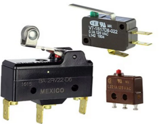
MICRO SWITCH HD Series switches are precision snap-action contact mechanisms enclosed in molded plastic cases. Switch actuation triggers the mechanical closure of the switch’s contacts. A small amount of arcing between the contacts during contact closure occurs during normal operation. In order to obtain desired switch performance, the switch must be chosen based on the mechanical, electrical and environmental conditions of the application.
HD Series switches are designed for use in a wide range of applications.
TABLE 1. MOUNTING INFORMATION
| TABLE 1. MOUNTING INFORMATION | |||
| Switch series | Screw type* | Screw size | Tightening torque (max.) |
| HD | Pan head | 3,0 mm | 4,8 kg-cm [4.2 in-lb] |
*To prevent loosening of screws, use spring washers under screw heads and thread lock adhesive.
- Position the operating device perpendicular to the actuator/pushbutton to prevent side loading of the switch actuator or pushbutton.
- Position the operating device so that no force is applied to the pushbutton/actuator when the switch is in the free (open) position.
- The operating device should be positioned so that when the switch is in the operating position it should move the actuator no less than 70 % of the total travel. Setting the travel position so that less than 70 % of the total travel is used may cause poor contact or welding conditions due to an insufficient contact switching force.
- The operating device should never force the actuator/pushbutton to exceed the total travel position.
- For switches with angled terminals, insert an insulator separator between the switch body and the PC board (insulator separator thickness 0,2 mm to 0,4 mm [0.008 in to 0.016 in].
WIRING INFORMATION
- Connect wires firmly to terminals.
- Replace wires that have damaged insulation.
- Provide strain relief when the potential exists for forces to be transferred from the lead wires to the switch terminals.
PIN LOCATION

Note: The common pin is identifiable by its position on the end of the switch closest to the actuator/pushbutton. The normally open and normally closed contact positions are relative to the common pin, as shown.
MICROSWITCH HD BASIC SWITCHES, HD SERIES

SOLDERING GUIDELINES
When hand soldering switch terminals, do not exceed five seconds at 350ºC [662ºF]. Contacting the switch housing with the soldering device may damage the switch housing. Solder joints must not be moved for at least one minute after soldering.
When wave soldering, do not exceed five seconds at 260ºC [500ºF] or subject to aqueous wash. Use alcohol and swab to clean terminals. Use of no-clean flux is recommended.
ENVIRONMENTAL OPERATING CHARACTERISTICS
| TABLE 2. OPERATING TEMPERATURE RANGE | ||
| Terminal type (20, 30, 40, 50, 60, 70, 99) |
-40°C to 125°C [-40°F to 257°F] | |
|
Wired type (01, 02, 03) |
UL1007/UL1061 | -20°C to 80°C [-4°F to 176°F] |
| UL1430 | -20°C to 85°C [-4°F to 185°F] | |
| AVSS | -40°C to 85°C [-40°F to 185°F] | |
WARRANTY/REMEDY
Honeywell warrants goods of its manufacture as being free
of defective materials and faulty workmanship during the applicable warranty period. Honeywell’s standard product warranty applies unless agreed to otherwise by Honeywell
in writing; please refer to your order acknowledgment or consult your local sales office for specific warranty details.
If warranted goods are returned to Honeywell during the period of coverage, Honeywell will repair or replace, at its option, without charge those items that Honeywell, in its sole discretion, finds defective. The foregoing is the buyer’s sole remedy and is in lieu of all other warranties, expressed or implied, including those of merchantability and fitness for a particular purpose. In no event shall Honeywell be liable for consequential, special, or indirect damages.
While Honeywell may provide application assistance personally, through our literature and the Honeywell web site, it is buyer’s sole responsibility to determine the suitability of the product in the application.
Specifications may change without notice. The information we supply is believed to be accurate and reliable as of this writing. However, Honeywell assumes no responsibility for its use.
FOR MORE INFORMATION
Honeywell Sensing and Internet of Things services its customers through a worldwide network of sales offices and distributors. For application assistance, current specifications, pricing, or the nearest Authorized Distributor,
visit sps.honeywell.com/ast or call:
- USA/Canada +302 613 4491
- Latin America +1 305 805 8188
- Europe +44 1344 238258
- Japan +81 (0) 3-6730-7152
- Singapore +65 6355 2828
- Greater China +86 4006396841
Honeywell Advanced Sensing Technologies
- 830 East Arapaho Road
- Richardson, TX 75081
- sps.honeywell.com/ast