Makita HR1840 Rotary Hammer Instruction Manual


INSTRUCTION MANUAL
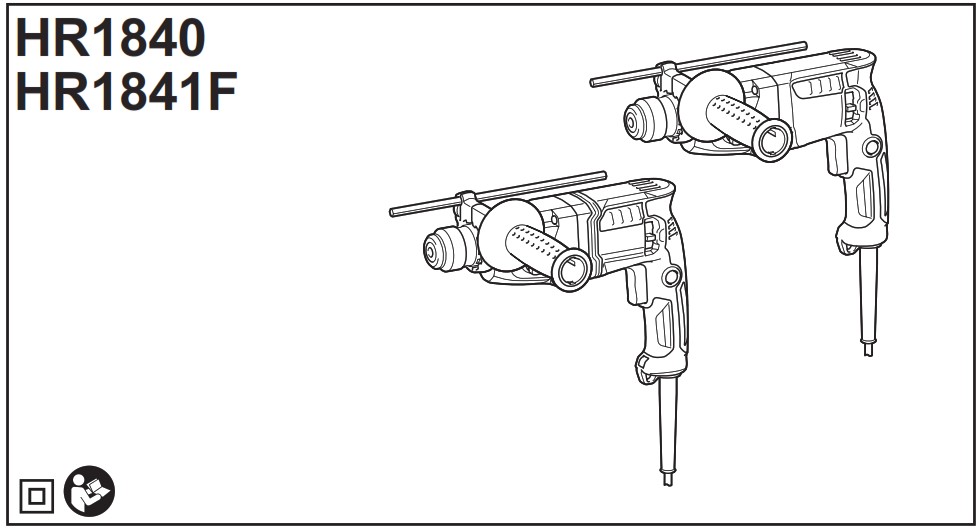


SPECIFICATIONS
| Model: | HR1840 | HR1841F | |
| Capacities | Concrete | 18 mm | |
| Core bit | 35 mm | ||
| Diamond core bit (dry type) | 65 mm | ||
| Steel | 13 mm | ||
| Wood | 24 mm | ||
| No load speed | 0 – 2,100 min¹ | ||
| Blows per minute | 0 – 4,800 min¹ | ||
| Overall length | 285 mm | ||
| Net weight | 2.0 – 2.4 kg | 2.0 – 2.5 kg | |
| Safety class | |||

- Due to our continuing program of research and development, the specifications herein are subject to change without notice.
- Specifications may differ from country to country.
- The weight may differ depending on the attachment(s). The lightest and heaviest combinations, according to
EPTA-Procedure 01/2014, are shown in the table.
Intended use
The tool is intended for hammer drilling and drilling in brick, concrete and stone. It is also suitable for drilling without impact in wood, metal, ceramic and plastic.
Power supply
The tool should be connected only to a power supply of the same voltage as indicated on the nameplate, and can only be operated on single-phase AC supply. They are double-insulated and can, therefore, also be used from sockets without earth wire.
Noise
The typical A-weighted noise level determined according to EN62841-2-6:
Model HR1840
Sound pressure level (LpA): 85 dB (A)
Sound power level (LWA): 98 dB (A)
Uncertainty (K) : 3 dB (A)
Model HR1841F
Sound pressure level (LpA): 85 dB(A)
Sound power level (LWA): 96 dB (A)
Uncertainty (K) : 3 dB(A)
NOTE: The declared noise emission value(s) has been measured in accordance with a standard test method and may be used for comparing one tool with another.
NOTE: The declared noise emission value(s) may also be used in a preliminary assessment of exposure.

Vibration
The following table shows the vibration total value (tri-axial vector sum) determined according to applicable standard.
Model HR1840
| Work mode | Vibration emission | Uncertainty (K) | Applicable standard /
Test condition |
| Hammer drilling into concrete (ah, HD) |
29.8 m/s² | 1.5 m/s² | EN62841-2-6 |
Model HR1841F
| Work mode | Vibration emission | Uncertainty (K) | Applicable standard /
Test condition |
| Hammer drilling into concrete ( ah, HD) |
8.9 m/s2 | 1.5 m/s2 | EN62841-2-6 |
| 7.9 m/s2 | 1.5 1.5 m/s2 | Recommended practical operation* |
* The test condition of recommended practical operation meets EN 62841-2-6, except for the following points:
- Feed force is applied to the switch handle (main handle) for working accuracy and efficiency.
- The side grip/handle (auxiliary handle) is held to keep balance of the tool.
NOTE: The declared vibration total value(s) has been measured in accordance with a standard test method and may be used for comparing one tool with another.
NOTE: The declared vibration total value(s) may also be used in a preliminary assessment of exposure.
EC Declaration of Conformity
For European countries only
The EC declaration of conformity is included as Annex A to this instruction manual.
SAFETY WARNINGS
General power tool safety warnings
Save all warnings and instructions for future reference.
The term “power tool” in the warnings refers to your mains-operated (corded) power tool or battery-operated (cordless) power tool.
ROTARY HAMMER SAFETY WARNINGS
Safety instructions for all operations
- Wear ear protectors. Exposure to noise can cause hearing loss.
- Use auxiliary handle(s), if supplied with the tool. Loss of control can cause personal injury.
- Hold the power tool by insulated gripping surfaces, when performing an operation where the cutting accessory may contact hidden wiring or its own cord. Cutting accessory contacting a “live” wire may make exposed metal parts of the power tool “live” and could give the operator an electric shock.
Safety instructions when using long drill bits with rotary hammers
- Always start drilling at low speed and with the bit tip in contact with the workpiece. At higher speeds, the bit is likely to bend if allowed to rotate freely without contacting the workpiece, resulting in personal injury.
- Apply pressure only in direct line with the bit and do not apply excessive pressure. Bits can bend, causing breakage or loss of control, resulting in personal injury.
Additional safety warnings
- Wear a hard hat (safety helmet), safety glasses and/or face shield. Ordinary eye or sun glasses are NOT safety glasses. It is also highly recommended that you wear a dust mask and thickly padded gloves.
- Be sure the bit is secured in place before operation.
- Under normal operation, the tool is designed to produce vibration. The screws can come loose easily, causing a breakdown or accident. Check tightness of screws carefully before operation.
- In cold weather or when the tool has not been used for a long time, let the tool warm up for a while by operating it under no load. This will loosen up the lubrication. Without proper warm-up, hammering operation is difficult.
- Always be sure you have a firm footing. Be sure no one is below when using the tool in high locations.
- Hold the tool firmly with both hands.
- Keep hands away from moving parts.
- Do not leave the tool running. Operate the tool only when hand-held.
- Do not point the tool at any one in the area when operating. The bit could fly out and injure someone seriously.
- Do not touch the bit, parts close to the bit, or workpiece immediately after operation; they may be extremely hot and could burn your skin.
- Some material contains chemicals which may be toxic. Take caution to prevent dust inhalation and skin contact. Follow material supplier safety data.
- Do not touch the power plug with wet hands.
SAVE THESE INSTRUCTIONS.
FUNCTIONAL DESCRIPTION
Switch action
released.
► Fig.1: 1. Switch trigger 2. Lock button
To start the tool, simply pull the switch trigger. Tool speed is increased by increasing pressure on the switch trigger. Release the switch trigger to stop.
For continuous operation, pull the switch trigger, push in the lock button and then release the switch trigger. To stop the tool from the locked position, pull the switch trigger fully, then release it.
Lighting up the front lamp
For HR1841F
► Fig.2: 1. Switch trigger 2. Lamp
To turn on the lamp, pull the switch trigger. Release the switch trigger to turn it off.
NOTICE: Do not use thinner or gasoline to clean the lamp. Such solvents may damage it.
NOTE: Use a dry cloth to wipe the dirt off the lens of the lamp. Be careful not to scratch the lens of lamp, or it may lower the illumination.
Reversing switch action
NOTICE: Use the reversing switch only after the tool comes to a complete stop. Changing the direction of rotation before the tool stops may damage the tool.
NOTICE: When changing the direction of rotation, be sure to fully set the reversing switch to position


► Fig.3: 1. Reversing switch lever
This tool has a reversing switch to change the direction of rotation. Move the reversing switch lever to the position

Selecting the action mode
NOTICE: Do not rotate the action mode changing knob when the tool is running. The tool will be damaged.
NOTICE: To avoid rapid wear on the mode change mechanism, be sure that the action mode changing knob is always positively located in one of the action mode positions.
Rotation with hammering
For drilling in concrete, masonry, etc., rotate the action mode changing knob to the

► Fig.4: 1. Action mode changing knob
Rotation only
For drilling in wood, metal or plastic materials, rotate the action mode changing knob to the symbol. Use a twist drill bit or wood drill bit.
► Fig.5: 1. Action mode changing knob
Torque limiter
NOTICE: As soon as the torque limiter actuates, switch off the tool immediately. This will help prevent premature wear of the tool.
NOTICE: Drill bits such as hole saw, which tend to pinch or catch easily in the hole, are not appropriate for this tool. This is because they will cause the torque limiter to actuate too frequently.
The torque limiter will actuate when a certain torque level is reached. The motor will disengage from the output shaft. When this happens, the drill bit will stop turning.
ASSEMBLY
Side grip (auxiliary handle)
Install the side grip so that the grooves on the grip fit in the protrusions on the tool barrel. Turn the grip clockwise to secure it. The grip can be fixed at desired angle.
► Fig.6: 1. Side grip
Grease
Coat the shank end of the drill bit beforehand with a small amount of grease (about 0.5 – 1 g).
This chuck lubrication assures smooth action and longer service life.
Installing or removing drill bit
Clean the shank end of the drill bit and apply grease before installing the drill bit.
► Fig.7: 1. Shank end 2. Grease
Insert the drill bit into the tool. Turn the drill bit and push it in until it engages.
After installing the drill bit, always make sure that the drill bit is securely held in place by trying to pull it out.
► Fig.8: 1. Drill bit
To remove the drill bit, pull the chuck cover down all the way and pull the drill bit out.
► Fig.9: 1. Drill bit 2. Chuck cover
Depth gauge
The depth gauge is convenient for drilling holes of uniform depth. Loosen the side grip and insert the depth gauge into the hole on the side grip. Adjust the depth gauge to the desired depth and tighten the side grip firmly.
► Fig.10: 1. Hole 2. Depth gauge
NOTE: Make sure that the depth gauge does not touch the main body of the tool when attaching it.
Dust cup
Optional accessory
Use the dust cup to prevent dust from falling over the tool and on yourself when performing overhead drilling operations. Attach the dust cup to the bit as shown in the figure. The size of bits which the dust cup can be attached to is as follows.
| Model | Bit diameter |
| Dust cup 5 | 6 mm – 14.5 mm |
| Dust cup 9 | 12 mm – 16 mm |
► Fig.11: 1. Dust cup
Dust cup set
Optional accessory
Installing the dust cup set
NOTICE: If you purchase the dust cup set as optional accessory, the standard side grip cannot be used with the dust cup set being installed on the tool. When the dust cup set is installed on the tool, remove the grip from the standard side grip, and then attach it to the optional grip base set.
► Fig.12: 1. Bolt 2. Grip 3. Optional grip base set
NOTICE: Do not use the dust cup set when drilling in metal or similar. It may damage the dust cup set due to the heat produced by small metal dust or similar. Do not install or remove the dust cup set with the drill bit installed in the tool. It may damage the dust cup set and cause dust leak.
Before installing the dust cup set, remove the bit from the tool if installed.
- Install the spacer so that the grooves on the spacer fit in the protrusions on the tool barrel while widening it. Be careful for the spring not to come off from the slit of spacer.
► Fig.13: 1. Spacer 2. Spring
► Fig.14 - Install the side grip (optional grip base set and the grip removed from standard side grip) so that the groove on the grip fit in the protrusion on the spacer. Turn the grip clockwise to secure it.
► Fig.15: 1. Side grip - Install the dust cup set so that the claws of the dust cup fit in in the slits on the spacer.
► Fig.16: 1. Dust cup 2. Claws
NOTE: If you connect a vacuum cleaner to the dust cup set, remove the dust cap before connecting it.
► Fig.17: 1. Dust cap
Removing the drill bit
To remove the drill bit, pull the chuck cover down all the way and pull the drill bit out.
► Fig.18: 1. Bit 2. Chuck cover
Removing the dust cup set
To remove the dust cup set, follow the steps below.
- Loosen the side grip.
► Fig.19: 1. Side grip - Hold the root of dust cup and pull it out.
► Fig.20: 1. Dust cup
NOTE: If it is difficult to remove the dust cup set, remove the claws of the dust cup one by one by swinging and pulling the root of the dust cup.
NOTE: If the cap comes off from the dust cup, attach it with its printed side facing up so that groove on the cap fits in the inside periphery of the attachment.
► Fig.21
OPERATION
► Fig.22
Hammer drilling operation
Set the action mode changing knob to the
Do not apply more pressure when the hole becomes clogged with chips or particles. Instead, run the tool at an idle, then remove the drill bit partially from the hole. By repeating this several times, the hole will be cleaned out and normal drilling may be resumed.
NOTE: Eccentricity in the drill bit rotation may occur while operating the tool with no load. The tool automatically centers itself during operation. This does not affect the drilling precision.

Drilling in wood or metal
NOTICE: Never use “rotation with hammering” when the drill chuck is installed on the tool. The drill chuck may be damaged.
Also, the drill chuck will come off when reversing the tool.
NOTICE: Pressing excessively on the tool will not speed up the drilling. In fact, this excessive pressure will only serve to damage the tip of your drill
bit, decrease the tool performance and shorten the service life of the tool.
Set the action mode changing knob to the
► Fig.23: 1. Keyless drill chuck 2. Chuck adapter

Blow-out bulb
Optional accessory
After drilling the hole, use the blow-out bulb to clean the dust out of the hole.
► Fig.24
Using dust cup set
Optional accessory
Fit the dust cup set against the ceiling when operating the tool.
► Fig.25
NOTICE: Do not use the dust cup set when drilling in metal or similar. It may damage the dust cup set due to the heat produced by small metal dust
or similar.
NOTICE: Do not install or remove the dust cup set with the drill bit installed in the tool. It may damage the dust cup set and cause dust leak.
MAINTENANCE
maintenance.
NOTICE: Never use gasoline, benzine, thinner,
alcohol or the like. Discoloration, deformation or
cracks may result.
To maintain product SAFETY and RELIABILITY, repairs, any other maintenance or adjustment should be performed by Makita Authorized or Factory Service Centers, always using Makita replacement parts.
OPTIONAL ACCESSORIES
If you need any assistance for more details regarding these accessories, ask your local Makita Service Center.
- Carbide-tipped drill bits (SDS-Plus carbide-tipped bits)
- Core bit
- Diamond core bit
- Chuck adapter
- Keyless drill chuck
- Bit grease
- Depth gauge
- Blow-out bulb
- Dust cup
- Dust cup set
- Grip base set
- Safety goggles
- Plastic carrying case
NOTE: Some items in the list may be included in the tool package as standard accessories. They may differ from country to country.
Makita Europe N.V.
Jan-Baptist Vinkstraat 2, 3070 Kortenberg, Belgium
Makita Corporation
3-11-8, Sumiyoshi-cho, Anjo, Aichi 446-8502 Japan
885579D997 EN, FR, DE, IT, NL, ES, PT, DA, EL, TR 20220603