Huawei UPS5000-S-1600KVA-FP High-Efficiency Modular Power Supply User Guide

Modular Power Supply
User Guide

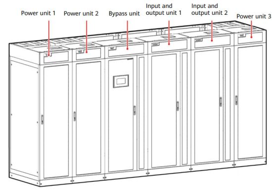
Overview
| Model | UPS5000-S-1600KVA-FP |
| Dimensions (H x W x D) | 2200 mm x 4200 mm x 1000 mm |
NOTICE
- Before installation, read the user manual carefully to get familiar with product information and safety precautions.
- Use insulated tools during installation and operation.
- Only engineers certified by Huawei or its agents are allowed to install, commission, and maintain the UPS. Otherwise, personal injury or equipment damage may occur, and the UPS faults caused are beyond the warranty scope of Huawei.


| (1) Surge protective device (SPD) box | (7) Output circuit breaker of the power unit 2 (Q5-2) |
| (2) Power modules | (8) Input circuit breaker of the power unit 2 (Q1-2) |
| (3) Bypass module | (9) Input circuit breaker of the power unit 1 (Q1-1) |
| (4) Monitoring module | (10) Output circuit breaker of the power unit 1 (Q5-1) |
| (5) SPD and SPD switch | (11) Output circuit breaker of the power unit 3 (Q5-3) |
| (6) Bypass control module | (12) Input circuit breaker of the power unit 3 (Q1-3) |
Installing the UPS
Determining the UPS Installation Position
The UPS can be installed on the channel steel or floor. Determine the mounting hole positions using a marking-off template (unit: mm), drill holes, and install expansion sleeves based on on-site requirements.
Dimensions of the Cabinet Holes

Combining the Power Units and Bypass Unit
- Remove the left and right side panels from the input and output units.
- Combine the power units, bypass unit, and input/output units, and install the connecting plates in the following sequence: bottom, top, and middle.
- Install the side panels removed from the input and output unit to power unit 1 and power unit 3.
- Secure the UPS.
(A) Mounting holes on the channel steel: M12x60 bolts
(B) Mounting holes on the floor: M12x60 expansion bolts
Channel steel or bolts are not included. - Install anchor baffle plates.


Installing Busbars
NOTICE
- Before handling a busbar, wear protective gloves to avoid getting injured by sharp edges.
- Move a busbar with caution to avoid scratching cabinets.
- Each busbar weighs about 50 kg. Be cautious to avoid injury when moving heavy objects.
Preparation: two scaling ladders that are more than one meter high
At least two persons are required to carry a busbar. At least two persons are required to hold the busbar on the top of the cabinet.
When moving a busbar, hold both ends of the busbar component. It is recommended that
the soft copper bar faces downward.
Do not move the busbar upward by holding the soft copper bar.
- Remove the front panels and dustproof covers from the top of the cabinets, and remove the connecting kits at both ends of the top of the power unit 1 unit and power unit 3.
- Install the U-shaped sealing plate component (numbered 01).
- Install busbar components (numbered 02 and 03).
- Use copper bars (numbered 04–06) to connect the busbar components (numbered 02 and 03).
NOTE
Before installation, remove the screws that are partially tightened from the busbar component. - Install the busbar component (numbered 07) and secure it to the cabinet.
- Install the left sealing plate (numbered 08).
- Install the side sealing plate (numbered 09) for the input and output unit.
- Install the side sealing plate (numbered 10) for power unit 3.
- Install the rear sealing plate (numbered 11) for power unit 1 and power unit 2.
- Install the sealing plates (numbered 12) for the bypass unit and input and output unit.
- Install the sealing plates (numbered 13) for power unit 3.
- Install the busbar (numbered 14) for power unit 3.
- Install the front and rear sealing plates (numbered 15 and 16) for input and output unit 2.
- Install the right sealing plate (numbered 17) for power unit 3.
- Install supports for the busbar covers.
- Install the sealing plate of battery wiring protective cover for each power unit.
- Install mounting plates (the left and right mounting plates are numbered 18).
- Install the top busbar covers.


Installing Cables
UPS Cable Connection Reference

- Prepare cables away from the cabinets to prevent scraps from falling inside. Cable scraps may ignite and cause personal injury or device damage.
- After cables have been installed, clean the cabinets in a timely manner. Keep the cabinets and surrounding environment clean and tidy.
- You need to prepare terminals onsite. The stripped length of the copper wire should be the same as that of the part of the terminal that covers the conductor.
The cabling route is for reference only. Connect cables based on on-site requirements.

Installing UPS Cables
Distances Between the Top Copper Bars of the Bypass Unit and Input and Output Unit (unit: mm)

Distances Between Top Copper Bars (unit: mm)

Copper Bar Specifications (unit: mm)

Copper Bar Positions (rear view of the cabinet)

| Port Description | Connection Method | Bolt Specifications | Bolt Length | Torque |
| Mains input | Crimped DT terminals | M12 | 35 mm | 47 N-m |
| Bypass input | Crimped DT terminals | M12 | 35 mm | 47 N-m |
| Battery input | Crimped DT terminals | M16 | 55 mm | 120 N-m |
| Output | Crimped DT terminals | M12 | 35 mm | 47 N-m |
| PE | Crimped DT terminals | M12 | 35 mm | 47 N-m |
| Equipotential ground point | Crimped DT terminals | M6 | N/A | 4.5 N-m |
- Connect the equipotential ground point and the ground bar in the equipment room.
- Connect the copper bars between the mains input and bypass input (N and PE copper bars).
- (Perform this step only when the mains input and bypass input share a power source) Install the copper bars (L1, L2, and L3 copper bars) between the mains input and bypass input.
- Install the U, V, and W copper bars.
- Connect input and output busbars and battery cables based on the top copper bar position diagram.
- Install supports and covers on the top of the protective covers for each power unit.
- Before power-on, remove the protective covers from the top of the power units.
- Connect the signal cables between the power unit, input and output unit, and bypass unit.
Cabinet Port Bypass Unit Port Power unit 1 XS1 BP-XS2 (02)
BP-XS6 (connect to the XS6 terminal reserved in the cabinet)Power unit 2 XS1 Power unit 3 XS1 BP-XS3 Input and output unit 2 (bound to input and output unit 1) N/A BP-XS4 Input and output unit 1 N/A BP-XS5 - Connect the signal cables between the power unit and bypass unit.
Cabinet Where the Signal Port Is Located Bypass Unit Port Power unit 1 Signal (PWU1) Power unit 2 Signal (PWU1) Power unit 3 Signal (PWU1) Verifying the Installation
- Check that there is no foreign matter in the cabinets.
- (Remove the paper protective film from the sealing putty.) After routing cables and verifying cable connections, seal the gap between cables and the cabinet using sealing putty.
- After verifying the installation, reinstall all the covers.
- Do not remove the dustproof cover before power-on to prevent dust from entering the UPS.
Powering On and Starting the UPS
NOTE
- Before powering on the UPS, ensure that the UPS has passed all check items in the UPS5000 Commissioning and Acceptance Report and Chapter 4.
- Measure the voltage and frequency of the mains and bypass inputs of the UPS, or the voltage and frequency output from the external input power distribution cabinet (PDC) to the UPS. Ensure that the line voltage is in the range of 138–485 V AC and the frequency is in the range of 40–70 Hz.
Powering On the UPS
NOTICE
When switching on an input or output circuit breaker, insert the ejector lever to the bottom and lift it with both hands to switch the circuit breaker to ON.Initial Startup
NOTICE
If the UPS is powered on for the first time, you need to obtain the startup password from the Service Expert app. Skip this step if the UPS is not powered on for the first time.
The Service Expert app can be downloaded from Google Play Store and can run on Android.- Obtain the startup password.
- Set the language, time, date, network parameters, and system parameters on the Settings Wizard screen.
- After you perform the settings, the Bypass mode and No battery alarms are reported by the MDU and do not need to be cleared. If there is any other alarm, you need to rectify the fault.
- If the system has connected to the remote EPO switch, you need to choose Monitoring > Param. Settings > System Settings on the WebUI and set EPO detection to Enable.
- View the system running status diagram on the MDU to check that the UPS is working in bypass mode.
Starting inverter
- On the main menu, choose Common Functions and tap Inv. ON.
- In the displayed login window, enter the user name and password, and tap
- In the displayed dialog box, tap Yes to start the inverter.
NOTE
To ensure system security, change the LCD and WebUI passwords after the first login.Default User Preset Password admin (administrator) LCD 1 Web Change me operator (common user) LCD 1 Web Change me browser (browsing user) Web N/A Powering On Loads
- After the inverter starts, the UPS works in normal mode. The Bypass mode alarm disappears.
- After confirming that the battery strings are properly connected, turn on the battery string input circuit breaker. If there are multiple battery strings, turn on the circuit breaker for each battery string and then the general circuit breaker between battery strings and the UPS. The No battery alarm disappears from the MDU.
- Turn on the UPS downstream output switch to supply power to loads.
(Optional) Setting Parameters for the BCB Box
- On the power unit LCD, choose Power Unit N Info. > Settings > Dry Contacts Set, set MUE05A connection to Enable and set BCB connection [OL] and Battery breaker [STA] to Enable.
NOTE
Power units 1 and 2 share the dry contact ports on control module 1, and power unit 3 uses the dry contact ports on control module 2. You need to set BCB box parameters on the LCD of each power unit.Shutting Down the UPS
NOTICE
After the inverter is shut down, if the bypass is normal, the UPS transfers to bypass mode; if the bypass is not normal, the UPS supplies no power. Before shutting down the UPS, ensure that all loads have shut down.Shutting Down the Inverter to Transfer the UPS to Bypass Mode
- Shutting down the inverter on the LCD.
On the system LCD, choose Common Functions > Inv. OFF. After confirmation, the inverter is shut down.
NOTE
You can also choose System Info > Maintenance > Inv. OFF to shut down the inverter. - Shutting down the inverter on the WebUI.
On the system, WebUI, choose Monitoring > Control and click Inv. OFF. After confirmation, the inverter is shut down.
Powering Off a Single UPS
NOTICE
When switching off an input or output circuit breaker, insert the ejector lever to the bottom and press it downwards with both hands to switch the circuit breaker to OFF.Scan here for technical support (enterprise):
Huawei App Store
Scan here for technical support (carrier):
Huawei App Store
Scan here for more documents:
https://support.huawei.com/carrierindex/en/hwe/index.html
http://weixin.qq.com/r/0Uzq8uHEJLxbraWR9xnDYou can also log in to Huawei technical support website:
https://support.huawei.com/enterprise
https://support.huawei.comHuawei Technologies Co., Ltd.
Huawei Industrial Base, Bantian, Longgang Shenzhen 518129 People’s Republic of China
www.huawei.com


