SIEMENS RCC10 Series Room Temperature Controllers User Manual


SIEMENS RCC10 Series Room Temperature Controllers

Room Temperature Controllers
for two-pipe fan coil units
- Output for on / off valve actuator
- Outputs for three-speed fan
- Control depending on the room or return air temperature (RCC10)
- Automatic heating / cooling changeover
- Operating modes of RCC10: normal, energy saving and frost protection mode or OFF
- Operating modes of RCC10.1: normal and energy saving mode or OFF Operating mode changeover input for remote control
- Function for avoiding damage resulting from moisture (RCC10.1)
- Selectable control parameters (RCC10)
- Operating voltage AC 230 V
Use
Typical use:
- Control of the room temperature in individual rooms that are heated or cooled with two-pipe fan coil units.
- For opening or closing a valve and for switching a three-speed fan.
Suitable for use in systems with
- automatic heating/cooling changeover
- continuous heating or cooling operation.
Functions
The controller acquires the room temperature with its integrated sensor or external room temperature sensor (QAA32) or external return air temperature sensor (QAH11.1) – if used (optional with the RCC10) – and maintains the setpoint by delivering control commands to the 2-point-valve.
The switching differential with the
- RCC10 is adjustable; it can be 1 or 4 K in heating mode and 0.5 or 2 K in cooling mode
- RCC10.1 is fixed; it is 2 K in heating mode and 1 K in cooling mode
Fan operation
The fan is switched to the selected speed via control output Q1, Q2 or Q3.
When the function “Temperature-dependent fan control” is activated (can be selected with DIP switch no.1), the fan is switched on / off depending on the temperature, that is, together with the valve.
It is switched off by
- leaving the heating or cooling sequence, provided the function “Temperature-dependent fan control” is activated, or
- manually changing to standby, provided plant conditions do not call for frost protection mode (only with the RCC10), or
- activating an external operating mode changeover switch, provided plant conditions do not call for energy saving or frost protection mode (only with the RCC10), or
- turning the controller’s power supply off.
Heating and cooling mode
ON
The heating or cooling valve receives the OPEN command via control output Y11 when
- the measured room temperature lies by half the switching differential below the setpoint (heating mode) or above the setpoint (cooling mode), and
- the valve has been fully closed for more than one minute.
OFF
The heating or cooling valve receives the CLOSE command via control output Y11 when
- the measured room temperature lies by half the switching differential above the setpoint (heating mode) or below the setpoint (cooling mode), and
- the valve has been fully open for more than one minute.
Note: control output Y12 delivers a control command which is inverted to the control command at output Y11 and can be used for normally open valves
Return air tempera-ture
The RCC10 provides control either depending on the measured room temperature or depending on the fan coil unit’s return air temperature. Changeover is automatic if a QAH11.1 cable temperature sensor is connected.
Automatic changeover
The water temperature acquired by the changeover sensor (QAH11.1 + ARG86.3) is used by the controller to switch from heating to cooling mode, or vice versa. When the water temperature lies above 28 °C, the controller switches to heating mode, below 16 °C it switches to cooling mode. If, immediately after switching on, the water temperature lies between the 2 changeover points, the controller will start in heating mode. The water temperature is measured at minute-intervals and the operational status updated.

Purging function
he task of the changeover sensor is to initiate the change from heating to cooling mode even if the two-port valves are shut down for a longer period of time. To ensure this function, the valves are opened for one minute at 2-hour intervals during off hours.(Note: this function is not effective when using thermal actuators)
Energy saver
The room temperature setpoint can be limited in increments of 1 K by making use of the minimum and maximum limitation facility. Arbitrary setpoint readjustments can thus be prevented.
Operating modes
The following operating modes are available:
Normal operation: Heating or cooling mode with automatic changeover and with manually selected fan speed III, II or I. In normal operation, the controller maintains the adjusted setpoint.
Frost protection mode (only with the RCC10): The frost protection function is activated only when DIP switch no.4 is set to OFF. Frost protection mode can be activated either
- by manually switching to standby.
- by activating the external operating mode changeover switch, provided DIP switch no.2 is set to OFF
If the room temperature falls below 8 °C, the controller will automatically switch to frost protection mode. In that case, the heating valve opens and the fan operates at the selected speed. If the operating mode selector is in position standby , the fan will oper-ate at speed I. The room temperature is maintained at a setpoint of 8 °C and the set-point adjusted by the user will be ignored.
If frost protection mode is locked (DIP switch no.4 in position ON), standby is locked also, which means that the controller will not switch to standby but to OFF:
Energy-saving mode: In energy-saving mode, the setpoint of heating is 16 °C and the setpoint of cooling 28 °C, independent of the position of the setpoint knob. This operating mode will be activated when input D1 for operating mode changeover is active and DIP switch no.2 is set to ON.
Avoiding damage resulting from mois-ture
(only with the RCC10.1) Operating mode changeover switch
To avoid damage due to moisture in very warm or humid climatic zones resulting from lack of air circulation in energy saving mode, the fan will not be switched off when se-lecting the function “Temperature-independent fan control” (with DIP switch no.1)
A changeover switch can be connected to status input D1-GND. When the switch clos-es its contact (caused by an open window, for instance), the operating mode will change from normal operation to energy saving mode (provided DIP switch no.2 is set to ON), or from normal operation to standby (provided DIP switch no.2 is set to OFF). If the room temperature falls below 8 °C and if DIP switch no.3 is set to OFF, frost protec-tion mode will become active.
The operating action of the switch (N.C. or N.O.) can be selected.
Type summary
Type reference Features
- RCC10 With input for return air temperature sensor
- RCC10.1 *) Without input for return air temperature sensor,
without frost protection function
Ordering
When ordering, please give name and type reference.
The QAH11.1 temperature sensor (can be used as a return air temperature or changeover sensor), the changeover sensor mounting kit and the valves are to be ordered as separate items.
Equipment combinations
- Type of unit Type reference Datasheet*)
- Temperature sensor QAH11.1 1840
- Room sensor QAA32 1747
- Changeover mounting kit ARG86.3 1840
- Motoric on/off actuator SFA21… 4863
- Thermal actuator (for radiator valve) STA21… 4893
- Thermal actuator (for small valve 2,5 mm) STP21… 4878
*) The documents can be downloaded from http://siemens.com/bt/download.
Mechanical design
The unit consists of two parts:
- A plastic housing which accommodates the electronics, the operating elements and the built-in room temperature sensor
- A mounting base The housing engages in the mounting base and snaps on.
The base carries the screw terminals. The DIP switches are located at the rear of the housing.
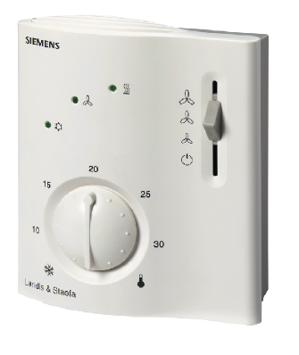
Setting and operating elements

Legend
- Operating mode selector (standby , heating or cooling mode with manual selection of fan speed)
- LEDs for indicating heating mode, cooling mode and fan operation
- Setting facility for minimum setpoint limitation (in increments of 1 K)
- Setting facility for maximum setpoint limitationN (in increments of 1 K)
- Room temperature setpoint knob
Set of DIP switches
| DIP switch no. | Meaning | Position ON | Position OFF |
| 1 | Fan control | Fan control is temperature- dependent in all operating modes | Fan control in normal operation (and in energy saving mode with the RCC10.1) is temperature independent1) |
| 2 | Operating mode changeo- ver via external switch | Changeover between normal operation and energy saving mode | Changeover between normal operation and standby 1) |
| 32) | Operating action of switch for external operating mode changeover |
Changeover activated when contact of switch is closed (N.O.)1) |
Changeover activated when contact of switch is open (N.C.) |
| 42) | Standby | Frost protection function not enabled | Frost protection function enabled 1) |
| 52) | Switching differential | 1 K in heating mode 1) 0.5 K in cooling mode 1) |
4 K in heating mode 2 K in cooling mode |
The RCC10.1 comes with the following fixed settings:
- Switching differential in heating mode: 2 K
- Switching differential in cooling mode: 1 K
- Standby: OFF, no frost protection
- Operating action of switch for external operating mode changeover: N.O.
Engineering notes
In systems with automatic changeover, the temperature sensor can be replaced by an external switch for manual changeover.
In systems with the continuous heating operation, no sensor will be connected to the controller’s input.
With the continuous cooling operation, the controller input (B2–M) must be bridged.
Mounting, installation and commissioning notes

Mounting location: on a wall or inside the fan coil unit. Not in niches or bookshelves, not behind curtains, above or near heat sources and not exposed to direct solar radiation. Mounting height is about 1.5 m above the floor. The connecting wires can be run to the controller from a recessed conduit box.
Check the settings of the DIP switches no.1 through no.5 (with the RCC10) and of no.1 and no.2 (with the RCC10.1) and change them, if required. If setpoint limitation is required, use the minimum and maximum limitation facility (energy saver). After applying power, the controller makes a reset during which the fan LED flashes, indicating that the reset has been correctly made. This takes about 3 seconds. Then, the controller will be ready to operate.
- Prior to fitting the changeover sensor, thermally conductive paste must be applied to the location on the pipe where the sensor is placed
- The cables used must satisfy the insulation requirements with regard to mains potential
- Sensor inputs B1–M and B2–M carry mains potential. If the sensor’s cables must be extended, the cables used must be suited for mains voltage
Warning!
No internal line protection for supply lines to external consumers (Q1, Q2, Q3, Y11, Y12)
Risk of fire and injury due to short-circuits!
- Adapt the line diameters as per local regulations to the rated value of the installed overcurrent protection device.
The controller is supplied with Mounting Instructions.
Disposal
The device is considered an electronic device for disposal in accordance with European Directive and may not be disposed of as domestic waste.
- Use only designated channels for disposing the devices.
- Comply with all local and currently applicable laws and regulations.


