SIEMENS SIMATIC IPC Industrial Edge Device User Manual
SIEMENS SIMATIC IPC Industrial EdgeDevice User Manual

Legal information
Warning notice system
This manual contains notices you have to observe in order to ensure your personal safety, as well as to prevent damage to property. The notices referring to your personal safety are highlighted in the manual by a safety alert symbol, notices referring only to property damage have no safety alert symbol. These notices shown below are graded according to the degree of danger.
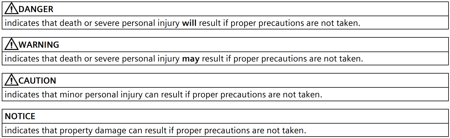

If more than one degree of danger is present, the warning notice representing the highest degree of danger will be used. A notice warning of injury to persons with a safety alert symbol may also include a warning relating to property damage.
Qualified Personnel
The product/system described in this documentation may be operated only by personnel qualified for the specific task in accordance with the relevant documentation, in particular its warning notices and safety instructions.
Qualified personnel are those who, based on their training and experience, are capable of identifying risks and avoiding potential hazards when working with these products/systems.
Proper use of Siemens products
Note the following:
| Siemens products may only be used for the applications described in the catalog and in the relevant technical documentation. If products and components from other manufacturers are used, these must be recommended or approved by Siemens. Proper transport, storage, installation, assembly, commissioning, operation and maintenance are required to ensure that the products operate safely and without any problems. The permissible ambient conditions must be complied with. The information in the relevant documentation must be observed. |

Trademarks
All names identified by ® are registered trademarks of Siemens AG. The remaining trademarks in this publication may be trademarks whose use by third parties for their own purposes could violate the rights of the owner.
Disclaimer of Liability
We have reviewed the contents of this publication to ensure consistency with the hardware and software described. Since variance cannot be precluded entirely, we cannot guarantee full consistency. However, the information in this publication is reviewed regularly and any necessary corrections are included in subsequent editions.
1 Preface
Purpose of this document
This documentation provides the basic information you need to manage and run the Industrial Edge Device OS.
This documentation is aimed at operators who, for example, commission and operate Edge Devices or install and run Edge Apps, as well as service and maintenance technicians who perform error analysis.
Basic knowledge required
- Solid knowledge of personal computers is
- Solid knowledge of Linux-based operating systems is
- Solid knowledge of IP-based networks is
- Solid knowledge of Docker is
- General knowledge in the field of IT is
- General knowledge in the field of automation technology is
Scope of this document
This operating manual is valid for Industrial Edge.
Convention
The term “Edge Device” is used in this documentation to designate hardware with a configured Industrial Edge Device OS.
Instead of the product designation “Industrial Edge Device”, the short form “Edge Device” is also used.
Figures
Picture components are marked with black position numbers on a white background: ①, ②, ③, etc.
2 Industrial security
Siemens provides products and solutions with industrial security functions that support the secure operation of plants, systems, machines and networks.
In order to protect plants, systems, machines and networks against cyber threats, it is necessary to implement – and continuously maintain – a holistic, state-of-the-art industrial security concept. Siemens’ products and solutions constitute one element of such a concept.
Customers are responsible for preventing unauthorized access to their plants, systems, machines and networks. Such systems, machines and components should only be connected to an enterprise network or the internet if and to the extent such a connection is necessary and only when appropriate security measures (e.g. firewalls and/or network segmentation) are in place.
For additional information on industrial security measures that may be implemented, please visit (http://www.siemens.com/industrialsecurity).
Siemens’ products and solutions undergo continuous development to make them more secure. Siemens strongly recommends that product updates are applied as soon as they are available and that the latest product versions are used. Use of product versions that are no longer supported, and failure to apply the latest updates may increase customer’s exposure to cyber threats.
To stay informed about product updates, subscribe to the Siemens Industrial Security RSS Feed at (https://support.industry.siemens.com/cs/start?).
In addition, observe the security statements, which are also valid for this documentation, from the “Industrial Edge – Security overview (https://support.industry.siemens.com/cs/us/en/view/109781002)” manual.
3 Connecting an IPC Edge Device
You have the following options to connect the IPC Edge Device to the IEM:
- Connecting through an USB flash drive
- Connecting through the IPC Edge Device UI
Both options require the IPC Edge Device configuration file.
Requirements for adding an Edge Device
- The IPC Edge Device is switched
- The IPC Edge Device is connected to the local
3.1 Connecting the Edge Device through an USB flash drive
Requirement
- 1 USB flash drive is
- The Edge Device configuration file has been
Procedure
- Copy the Edge Device configuration file on an USB flash Ensure that just 1 configuration file is saved to the USB flash drive. Otherwise, the connecting process causes problems and fails.
- Insert the USB flash drive into the Edge The connecting process is being started automatically. The “Run” LED flashes green and the “Maintenance” LED flashes yellow.
- Wait until the connecting process is When the Edge Device is connected successfully to the IEM, the “Run” LED lights up green.
Note
Connection successful
When the Edge Device is connected successfully to the IEM, the status indicator at the top of the Edge Device tile in the IEM switches to green and the IP address of the Edge Device is displayed under the name of the Edge Device.
To open the UI of the Edge Device, either click on the tile of the Edge Device, if the remote access is enabled, or enter the IP address of the Edge Device into your Internet browser.
Use the HTTPS protocol, for example “https://192.168.80.123”.
Note
Log file “conf-usb.log” and log file “services.log”
During the connecting process, the “conf-usb.log” and “services.log” files are created in the USB flash drive. In case of any errors, open these log files in a text editor for detailed information. In addition, you can check the steps of each service, if it was successful or not, in the “services.log” file.
Supported USB File Systems and Partition System Combinations
The following File Systems and Partitions are supported in the system:
- File Systems FAT32, NTFS and ext4 (Linux format)
- Partitions MBR, GPT
4 LED Status
The SIMATIC IPC227E (MLFB: 6ES7647-8BD31-0CW1) has 4 LEDs which represent the following status:

| ① | Power |
| ② | Run |
| ③ | Error |
| ④ | Maintenance |
Figure 4-1 SIMATIC IPC227E
The SIMATIC IPC427E (MLFB: 6AG4141-5BC30-0FW8) has 4 LEDs which represent the following status:

| ① | Power |
| ② | Run |
| ③ | Error |
| ④ | Maintenance |
Figure 4-2 SIMATIC IPC427E
List of all LED status
The following table lists all LED status changes of the Edge Device during several processes:
| Process | Description | Power | Run | Error | Maintenances |
| Not connected to the IEM | When the Edge Device is not connected to the IEM, the “Run” LED flashes green. | Green | Green flashing | Off | Off |
| Connecting to the IEM | When the Edge Device is connecting to the IEM (after the USB flash drive is inserted), the “Run” LED flashes green and the “Maintenance” LED flashes orange. | Green | Green flashing | Off | Orange flashing |
| Connection to the IEM was successful | When the Edge Device is connected successfully to the IEM, the “Run” LED lights up green. | Green | Green | Off | Off |
| Connection to the IEM failed | When the connection to the IEM has failed, the “Error” LED flashes red. | Green | Off | Red flashing | Off |
| IED-OS updates | When IED-OS updates are in progress, the “Maintenance” LED flashes orange. | Green | Off | Off | Orange flashing |
| During the hard reset of an Edge Device | When you initiate the hard reset, first the “Power” and “Run” LEDs light up green. After that, the “Power” LED lights up green and the “Run” LED flashes green. Then, all LEDs light up for a short time. Afterwards, the “Power” LED flashes orange. Then, the “Power” LED lights up green for a while. At the end, only the “Power” LED lights up green and the “Run” LED flashes green. | Orange flashing | Off | Off | Off |
| Hard reset was successful | When the “Power” LED lights up green and the “Run” LED flashes green, the hard reset was successful. The Edge Device is not connected anymore to the IEM in this case. | Green | Green flashing | Off | Off |
| During the system reset of an Edge Device | When you initiate the system reset, first the “Power” and “Run” LEDs light up green and after that, the “Error” and “Maintenance” LED light up red additionally. Then, the “Power” LED flashes orange. Afterwards, the “Power” LED lights up green and the “Run” LED flashes green. At the end, only the “Power” and “Run” LEDs light up green. | Orange flashing | Off | Off | Off |
| System reset was successful | When the “Power” and “Run” LEDs light up green, the system reset was successful. The Edge Device is still connected to the IEM in this case. | Green | Green | Off | Off |
| Shutting down the Edge Device | After you have shutdown the Edge Device, the “Power” LED lights up orange. | Orange | Off | Off | Off |
5 Preparing the USB stick
5.1 Preparing the USB stick for Windows
Requirement
USB flash drive’s size should be at least 4 GB.
Procedure
- Plug USB stick to your Windows
- Open “Create and format hard disk partitions” via “Start > Control Panel > System and Security > Administrative Tools”.
- Check, if USB stick has at least 1 GB unallocated space and proceed with Step If not, remove other partitions/data in USB stick.

- To delete a partition, right click on USB stick and click “Delete Volume…”. All files in USB stick will be deleted after this

- To create a new volume on your USB stick, right click on the unallocated USB space and select “New Simple Volume…”.


- Confirm your entries with “Next” until “Format Partition” Select “File system” as “FAT32”.
- Confirm your entries with “Next” and “Finish”.
- Copy onboard config file into USB partition named as “USBONBOARD”.

5.2 Preparing the USB stick for Linux
Requirement
USB flash drive’s size should be at least 4 GB.
Procedure
- Plug USB stick to your Linux PC (real device or virtual-machine).We recommend using one of the Debian Linux based distributions (i.e. Debian Linux, Ubuntu).
- Login as root or switch to If USB stick is mounted automatically, unmount USB-stick.
- To check availability of package “e2fsprogs”, run command “apt list –installed | grep e2fsprogs”. If there is no package installed, install the package “e2fsprogs”.
- To see partition of USB stick, run “lsblk” command The partition(s) are named like “/dev/sdb”.
- To search unallocated space, run “fdisk <your_usb_stick>” Example: fdisk /dev/sdb
- You need unallocated space which is bigger than 1 If there is no unallocated space bigger than 1 GB, delete partition by run “fdisk <your_usb_stick>” command. Press “d” and “w” for writing and exiting.
- To create a new partition, run “fdisk <your_usb_stick>” Press “n” and confirm by pressing “ENTER” until end. Press “w” for writing and exiting.

- To create ext4 file system, run command “mkfs.ext4 <usb_stick_partition_created_in_step8>”.
Example: mkfs.ext4 /dev/sdb1
- To label partition, run command “e2label <usb_stick_partition_created_in_step8> USBONBOARD”.
- Unplug and relog the USB
- Copy onboard config file into USB partition named as “USBONBOARD”.

6 Information and Warnings
Hard reset
It is not recommended to power-off the device during the hard reset process.
SIMATIC IPC Industrial Edge Device – Operation V1.3
Operating Manual, 09/2021, A5E51396302-AA