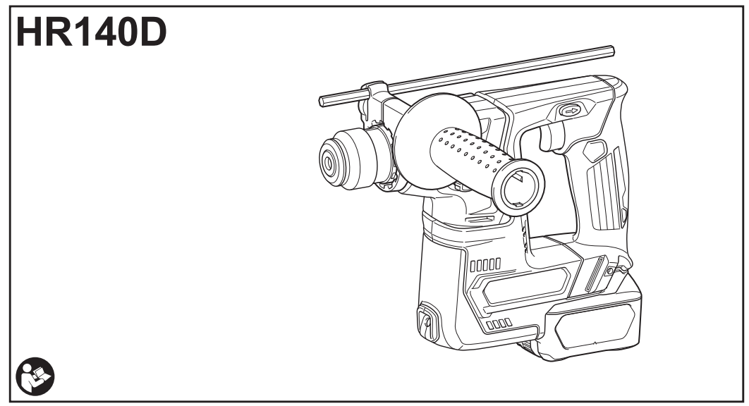
Makita HR140D Cordless Rotary Hammer Instruction Manual

INSTRUCTION MANUAL


SPECIFICATIONS
| Model: | HR140D | |
| Drilling capacities | Concrete | 14 mm |
| Steel | 10 mm | |
| Wood | 13 mm | |
| No load speed | 0 – 850 min., | |
| Blows per minute | 0 – 4,900 min-1 | |
| Overall length | 246 mm | |
| Rated voltage | D.C. 10.8 V – 12 V max | |
| Net weight | 1.9 – 2.6 kg | |
- Due to our continuing program of research and development, the specifications herein are subject to change without notice.
- Specifications may differ from country to country.
- The weight may differ depending on the attachment(s), including the battery cartridge. The lightest and heaviest combinations, according to EPTA-Procedure 01/2014, are shown in the table.
Applicable battery cartridge and charger
| Battery | BL1016 / BL1021B / BL1041B |
| Charger | DC10SA / DC10SB / DC10WC / DC10WD / DC18RE |
• Some of the battery cartridges and chargers listed above may not be available depending on your region of residence.
WARNING: Only use the battery cartridges and chargers listed above. Use of any other battery cartridges and chargers may cause injury and/or fire.
Intended use
The tool is intended for hammer drilling and drilling in brick, concrete, and stone.
It is also suitable for drilling without impact in wood, metal, ceramic, and plastic.
Noise
The typical A-weighted noise level is determined according to EN62841-2-6:
Sound pressure level (LpA) : 84 dB (A)
Sound power level (LWA) : 95 dB (A)
Uncertainty (K) : 3 dB (A)
NOTE: The declared noise emission value(s) has been measured in accordance with a standard test method and may be used for comparing one tool with another.
NOTE: The declared noise emission value(s) may also be used in a preliminary assessment of exposure.

Vibration
The following table shows the vibration total value (tri-axial vector sum) determined according to the applicable standards.
| Work mode | Vibration emission |
Uncertainty (K) | Applicable standard / Test condition |
| Hammer drilling into concrete (ah HD) | 7.0 m/s2 | 1.5 m/s2 | EN62841-2-6 |
| 7.7 m/s2 | 2.3 m/s2 | Recommended practical operation* |
* The test condition of recommended practical operation meets EN 62841-2-6, except for the following points:
- Feed force is applied to the switch handle (main handle) for working accuracy and efficiency.
- The side grip/handle (auxiliary handle) is held to keep the balance of the tool.
NOTE: The declared vibration total value(s) has been measured in accordance with a standard test method and may be used for comparing one tool with another.
NOTE: The declared vibration total value(s) may also be used in a preliminary assessment of exposure.
EC Declaration of Conformity
For European countries, only The EC declaration of conformity is included as Annex A to this instruction manual.
SAFETY WARNINGS
General power tool safety warnings
Save all warnings and instructions for future reference.
The term “power tool” in the warnings refers to your mains-operated (corded) power tool or battery-operated (cordless) power tool.
CORDLESS ROTARY HAMMER SAFETY WARNINGS
Safety instructions for all operations
- Wear ear protectors. Exposure to noise can cause hearing loss.
- Use auxiliary handle(s), if supplied with the tool. Loss of control can cause personal injury.
- Hold the power tool by insulated gripping surfaces, when performing an operation where the cutting accessory may contact hidden wiring. Cutting accessory contacting a “live” wire may make exposed metal parts of the power tool “live” and could give the operator an electric shock.
Safety instructions when using long drill bits with rotary hammers
- Always start drilling at low speed and with the bit tip in contact with the workpiece. At higher speeds, the bit is likely to bend if allowed to rotate freely without contacting the workpiece, resulting in personal injury.
- Apply pressure only in direct line with the bit and do not apply excessive pressure. Bits can bend, causing breakage or loss of control, resulting in personal injury.
Additional safety warnings
- Wear a hard hat (safety helmet), safety glasses and/or face shield. Ordinary eye or sun glasses are NOT safety glasses. It is also highly recommended that you wear a dust mask and thickly padded gloves.
- Be sure the bit is secured in place before operation.
- Under normal operation, the tool is designed to produce vibration. The screws can come loose easily, causing a breakdown or accident. Check tightness of screws carefully before operation.
- In cold weather or when the tool has not been used for a long time, let the tool warm up for a while by operating it under no load. This will loosen up the lubrication. Without proper warm-up, hammering operation is difficult.
- Always be sure you have a firm footing. Be sure no one is below when using the tool in high locations.
- Hold the tool firmly with both hands.
- Keep hands away from moving parts.
- Do not leave the tool running. Operate the tool only when hand-held.
- Do not point the tool at anyone in the area when operating. The bit could fly out and injure someone seriously.
- Do not touch the bit, parts close to the bit, or workpiece immediately after operation; they may be extremely hot and could burn your skin.
- Some material contains chemicals that may be toxic. Take caution to prevent dust inhalation and skin contact. Follow material supplier safety data.
- Always be sure that the tool is switched off and the battery cartridge and the bit are removed before handing the tool to another person.
- Before the operation, make sure that there is no buried object such as an electric pipe, water pipe or gas pipe in the working area. Otherwise, the drill bit/chisel may touch them, resulting an electric shock, electrical leakage or gas leak.
- Do not operate the tool at no-load unnecessarily.
SAVE THESE INSTRUCTIONS.
WARNING: DO NOT let comfort or familiarity with product (gained from repeated use) replace strict adherence to safety rules for the subject product. MISUSE or failure to follow the safety rules stated in this instruction manual may cause serious personal injury.
- Before using the battery cartridge, read all instructions and cautionary markings on (1) battery charger, (2) battery, and (3) product using the battery.
- Do not disassemble or tamper with the battery cartridge. It may result in a fire, excessive heat, or explosion.
- If the operating time has become excessively shorter, stop operating immediately. It may result in a risk of overheating, possible burns, and even an explosion.
- If electrolyte gets into your eyes, rinse them out with clear water and seek medical attention right away. It may result in loss of your eyesight.
- Do not short the battery cartridge:
- Do not touch the terminals with any conductive material.
- Avoid storing battery cartridges in a container with other metal objects such as nails, coins, etc.
- Do not expose the battery cartridge to water or rain.
A battery short can cause a large current flow, overheating, possible burns and even a breakdown.
- Do not store and use the tool and battery cartridge in locations where the temperature may reach or exceed 50 °C (122 °F).
- Do not incinerate the battery cartridge even if it is severely damaged or is completely worn out. The battery cartridge can explode in a fire.
- Do not nail, cut, crush, throw, drop the battery cartridge, or hit a hard object to the battery cartridge. Such conduct may result in a fire, excessive heat, or explosion.
- Do not use a damaged battery.
- The contained lithium-ion batteries are subject to the Dangerous Goods Legislation requirements. For commercial transports e.g. by third parties, forwarding agents, special requirements on packaging and labeling must be observed. For the preparation of the item being shipped, consulting an expert for hazardous material is required. Please also observe possibly more detailed national regulations. Tape or mask off open contacts and pack up the battery in such a manner that it cannot move around in the packaging.
- When disposing of the battery cartridge, remove it from the tool and dispose of it in a safe place. Follow your local regulations relating to the disposal of batteries.
- Use the batteries only with the products specified by Makita. Installing the batteries to non-compliant products may result in a fire, excessive heat, explosion, or leak of electrolyte.
- If the tool is not used for a long period of time, the battery must be removed from the tool.
- During and after use, the battery cartridge may take on heat which can cause burns or low-temperature burns. Pay attention to the handling of hot battery cartridges.
- Do not touch the terminal of the tool immediately after use as it may get hot enough to cause burns.
- Do not allow chips, dust, or soil to stuck into the terminals, holes, and grooves of the battery cartridge. It may cause heating, catching fire, burst, and malfunction of the tool or battery cartridge, resulting in burns or personal injury.
- Unless the tool supports the use of near high-voltage electrical power lines, do not use the battery cartridge near high-voltage electrical power lines. It may result in a malfunction or breakdown of the tool or battery cartridge. 18. Keep the battery away from children.
SAVE THESE INSTRUCTIONS.
CAUTION: Only use genuine Makita batteries.
Use of non-genuine Makita batteries, or batteries that have been altered, may result in the battery bursting causing fires, personal injury and damage. It will also void the Makita warranty for the Makita tool and charger.
Tips for maintaining maximum battery life
- Charge the battery cartridge before completely discharged. Always stop tool operation and charge the battery cartridge when you notice less tool power.
- Never recharge a fully charged battery cartridge. Overcharging shortens the battery service life.
- Charge the battery cartridge with room temperature at 10 °C – 40 °C (50 °F – 104 °F). Let a hot battery cartridge cool down before charging it.
- When not using the battery cartridge, remove it from the tool or the charger.
FUNCTIONAL DESCRIPTION
Installing or removing the battery cartridge
► Fig.1: 1. Red indicator 2. Button 3. Battery cartridge To remove the battery cartridge, slide it from the tool while sliding the button on the front of the cartridge. To install the battery cartridge, align the tongue on the battery cartridge with the groove in the housing and slip it into place. Insert it all the way until it locks in place with a little click. If you can see the red indicator as shown in the figure, it is not locked completely.
Battery protection system
The tool is equipped with a battery protection system.
This system automatically cuts off power to the motor to extend battery life.
The tool will automatically stop during operation if the tool and/or battery are placed under one of the following conditions:
Overloaded:
The tool is operated in a manner that causes it to draw an abnormally high current.
In this situation, turn the tool off and stop the application that caused the tool to become overloaded. Then turn the tool on to restart.
If the tool does not start, the battery is overheated. In this situation, let the battery cool before turning the tool on again.
Low battery voltage:
The remaining battery capacity is too low and the tool will not operate. If you turn the tool on, the motor runs again but stops soon. In this situation, remove and recharge the battery.
Indicating the remaining battery capacity
Only for battery cartridges with the indicator
► Fig.2: 1. Indicator lamps 2. Check button
Press the check button on the battery cartridge to indicate the remaining battery capacity. The indicator lamps light up for a few seconds.
| Indicator lamps | Remaining capacity | |
|
Off | |
| 75% to 100% | ||
| 50% to 75% | ||
| 25% to 50% | ||
| 0% to 25% | ||


NOTE: Depending on the conditions of use and the ambient temperature, the indication may differ slightly from the actual capacity.
Switch action
WARNING: Before installing the battery cartridge into the tool, always check to see that the switch trigger actuates properly and returns to the “OFF” position when released.
► Fig.3: 1. Switch Trigger
To start the tool, simply pull the switch trigger. Tool speed is increased by increasing pressure on the switch trigger. Release the switch trigger to stop.
Lighting up the front lamp
► Fig.4: 1. Switch trigger 2. Lamp
CAUTION: Do not look in the light or see the source of light directly.
Pull the switch trigger to light up the lamp. The lamp keeps on lighting while the switch trigger is being pulled.
The lamp goes out approximately 10 seconds after releasing the switch trigger.
NOTE: Use a dry cloth to wipe the dirt off the lens of the lamp. Be careful not to scratch the lens of the lamp, or it may lower the illumination.
Reversing switch action
► Fig.5: 1. Reversing switch lever
This tool has a reversing switch to change the direction of rotation. Depress the reversing switch lever from the A side for clockwise rotation or from the B side for counterclockwise rotation. When the reversing switch lever is in the neutral position, the switch trigger cannot be pulled.
Selecting the action mode
NOTICE: Do not rotate the action mode changing knob when the tool is running. The tool will be damaged.
NOTICE: To avoid rapid wear on the mode change mechanism, be sure that the action mode changing knob is always positively located in one of the action mode positions.
Rotation with hammering
For drilling in concrete, masonry, etc., rotate the action mode changing knob to the symbol. Use a carbide-tipped drill bit.
► Fig.6: 1. Action mode changing knob Rotation only
For drilling in wood, metal or plastic materials, rotate the action mode changing knob to the symbol. Use a twist drill bit or wood drill bit.
► Fig.7: 1. Action mode changing knob
ASSEMBLY
Side grip (auxiliary handle)
Install the side grip so that the grooves on the grip fit in the protrusions on the tool barrel. Turn the grip clockwise to secure it. The grip can be fixed at the desired angle. ► Fig.8: 1. Side grip
Grease
Coat the shank end of the drill bit beforehand with a small amount of grease (about 0.5 – 1 g).
This chuck lubrication assures smooth action and long service life.
Installing or removing the drill bit
Clean the shank end of the drill bit and apply grease before installing the drill bit.
► Fig.9: 1. Shank end 2. Grease
Insert the drill bit into the tool. Turn the drill bit and push it in until it engages.
After installing the drill bit, always make sure that the drill bit is securely held in place by trying to pull it out.
► Fig.10: 1. Drill bit
To remove the drill bit, pull the chuck cover down all the way and pull the drill bit out.
► Fig.11: 1. Drill bit 2. Chuck cover
Depth gauge
The depth gauge is convenient for drilling holes of uniform depth. Loosen the side grip and insert the depth gauge into the hole on the side grip. Adjust the depth gauge to the desired depth and tighten the side grip firmly.
► Fig.12: 1. Hole 2. Depth gauge
NOTE: Make sure that the depth gauge does not touch the main body of the tool when attaching it.
Dust cup
Optional accessory
Use the dust cup to prevent dust from falling over the tool and on yourself when performing overhead drilling operations. Attach the dust cup to the bit as shown in the figure. The size of bits to which the dust cup can be attached to is as follows.
| Model | Bit diameter |
| Dust cup 5 | 6 mm – 14.5 mm |
| Dust cup 9 | 12 mm – 16 mm |
► Fig.13: 1. Dust cup
Dust cup set
Optional accessory
Installing the dust cup set
NOTICE: If you purchase the dust cup set as an optional accessory, the standard side grip cannot be used with the dust cup set being installed on the tool. When the dust cup set is installed on the tool, remove the grip from the standard side grip, and then attach it to the optional grip base set.
► Fig.14: 1. Bolt 2. Grip 3. Optional grip base set
NOTICE: Do not use the dust cup set when drilling in metal or similar. It may damage the dust cup set due to the heat produced by small metal dust or similar. Do not install or remove the dust cup set with the drill bit installed in the tool. It may damage the dust cup set and cause dust leak. Before installing the dust cup set, remove the bit from the tool if installed.
- Install the spacer so that the grooves on the spacer fit in the protrusions on the tool barrel while widening it. Be careful for the spring not to come off from the slit of the spacer.
► Fig.15: 1. Spacer 2. Spring
► Fig.16 - Install the side grip (optional grip base set and the grip removed from standard side grip) so that the groove on the grip fit in the protrusion on the spacer.
turn the grip clockwise to secure it.
► Fig.17: 1. Side grip - Install the dust cup set so that the claws of the han dust cup fit in in the slits on the spacer.
► Fig.18: 1. Dust cup 2. Claws
NOTE: If you connect a vacuum cleaner to the dust cup set, remove the dust cap before connecting it.
► Fig.19: 1. Dust cap
Removing the drill bit
To remove the drill bit, pull the chuck cover down all the way and pull the drill bit out.
► Fig.20: 1. Bit 2. Chuck cover
Removing the dust cup set
To remove the dust cup set, follow the steps below.
- Loosen the side grip.
► Fig.21: 1. Side grip - Hold the root of the dust cup and pull it out.
► Fig.22: 1. Dust cup
NOTE: If it is difficult to remove the dust cup set, remove the claws of the dust cup one by one by swinging and pulling the root of the dust cup.
NOTE: If the cap comes off from the dust cup, attach it with its printed side facing up so that groove on the cap fits in the inside periphery of the attachment.
► Fig.23
Hook
Optional accessory
► Fig.24: 1. Groove 2. Hook 3. Screw
The hook is convenient for temporarily hanging the tool.
This can be installed on either side of the tool.
To install the hook, insert it into a groove in the tool housing on either side and then secure it with a screw.
To remove, loosen the screw and then take it out.
OPERATION
NOTE: If the battery cartridge is in low temperature, the tool’s capability may not be fully obtained. In this case, warm up the battery cartridge by using the tool with no load for a while to fully obtain the tool’s capability.
► Fig.25
Hammer drilling operation
Do not force the tool. Light pressure gives best results. Keep the tool in position and prevent it from slipping away from the hole. Do not apply more pressure when the hole becomes clogged with chips or particles. Instead, run the tool at an idle, then remove the drill bit partially from the hole. By repeating this several times, the hole will be cleaned out and normal drilling may be resumed.
NOTE: Eccentricity in the drill bit rotation may occur while operating the tool with no load. The tool automatically centers itself during operation. This does not affect the drilling precision.
Drilling in wood or metal
NOTICE: Never use “rotation with hammering” when the drill chuck is installed on the tool. The drill chuck may be damaged. Also, the drill chuck will come off when reversing the tool.
NOTICE: Pressing excessively on the tool will not speed up the drilling. In fact, this excessive pressure will only serve to damage the tip of your drill bit, decrease the tool performance and shorten the service life of the tool.
Set the action mode changing knob to the symbol.
Attach the chuck adapter to a keyless drill chuck to which 1/2″-20 size screw can be installed, and then install them to the tool. When installing it, refer to the section “Installing or removing drill bit”.
► Fig.26: 1. Drill chuck assembly 2. Chuck adapter
Blow-out bulb
Optional accessory
After drilling the hole, use the blow-out bulb to clean the dust out of the hole.
► Fig.27
MAINTENANCE
CAUTION: Always be sure that the tool is switched off and the battery cartridge is removed before attempting to perform inspection or maintenance.
NOTICE: Never use gasoline, benzine, thinner, alcohol or the like. Discoloration, deformation or cracks may result.
To maintain product SAFETY and RELIABILITY, repairs, any other maintenance or adjustment should be performed by Makita Authorized or Factory Service Centers, always using Makita replacement parts.
OPTIONAL ACCESSORIES
CAUTION: These accessories or attachments are recommended for use with your Makita tool specified in this manual. The use of any other accessories or attachments might present a risk of injury to persons. Only use accessory or attachment for its stated purpose.
If you need any assistance with more details regarding these accessories, ask your local Makita Service Center.
- Carbide-tipped drill bits (SDS-Plus carbide-tipped bits)
- Chuck adapter
- Keyless drill chuck
- Bit grease
- Depth gauge
- Blow-out bulb
- Dust cup
- Dust cup set
- Grip base set
- Safety goggles
- Hook
- Makita genuine battery and charger
- Plastic carrying case
NOTE: Some items in the list may be included in the tool package as standard accessories. They may differ from country to country.
Makita Europe N.V.
Makita Corporation
Jan-Baptist Vinkstraat 2,
3070 Kortenberg, Belgium
3-11-8, Sumiyoshi-cho,
Anjo, Aichi 446-8502 Japan
www.makita.com
885597C995
EN, FR, DE, IT, NL,
ES, PT, DA, EL, TR
20220603