Honeywell IM11-PRT RFID Module User Manual


Honeywell IM11-PRT RFID Module

Introduction
This document specifies the details for a IM11-PRT RFID MODULE
About IM11
IM11-PRT RFID Reader Module is designed for quick integration into computers, printers, and any other products that need to be RFID-enabled. The IM11 includes these features:
- Allows the RFID-enabled product to read and write to tags used in most worldwide applications:
- The IM11 can comply with the regulatory requirements for ETSI 4 channels in Europe, USA, Taiwan, Australia, Thailand, Brazil, Hong Kong, Malaysia, Singapore, China, Philippines, South Africa, Israel, South Korea, and New Zealand.
- The IM11 cannot comply with regulatory requirements for Japan.
- Operates across the entire frequency band. The country code defines the frequency bands of operation, the power levels, the hop tables, and other country-specific parameters. The default country code is defined by the location where the module is delivered.
- Covers UHF bands from 865 to 928 MHz Supports four channel operation over the 865 to 868 MHz band.
- Supports 50 channels in the FCC band from 902 to 928 MHz.
- Supports the ISO 18000-6c protocol (EPC Class 1, Gen 2)
- Supports the BRI (Basic Reader Interface) host communication protocol.
Technical Specifications


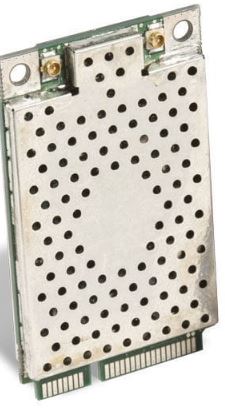
Mechanical Integration
The module fits within the Mini PCI Express specifications. For physical dimensions, see the illustration.

Electrical Integration
The module communicates either over USB or through serial:
- The USB client communication follows the CDC profile and is USB 2.0-compliant, operating at 12 Mbps (full speed).
- In Serial mode, the module communicates as a standard PC COM port, operating at 115.2 Kbps. It has eight general purpose inputs and outputs for monitoring and controlling external signals.
A Digital Signal Processor (DSP) controls the radio functions and provides communication with the host. This interface allows direct reprogramming and updating of the on-board FLASH memory
Power Requirements
The module operates off power input from 3.15 VDC to 5.2 VDC. If the input is 3.3 V DC or less, you must account for significant increased current demand. If the input drops below 3.15 VDC, 1 Watt output is not possible. The module handles its own power management and goes into Standby mode automatically when there are no outstanding commands. However, even in Standby mode, the IM11 immediately responds to host activity, eliminating any potential host timeout conditions. To achieve an even lower power Standby mode, the host needs to support USB suspend and remote wakeup. To reduce power, the module duty cycles its transmitter. The duty cycling happens according to the read commands that the application executes. To achieve the lowest power, after all tags are read, the transmitter turns off. After a period of time, the transmitter activates to identify new tags in the field. After all new tags are read, the transmitter turns off for the rest of the period. Also, the module automatically reduces the power out if the input voltage is too low or the temperature of the module is too high.
Reader Power States

You cannot turn off the RTC unless you remove power Pin 2 (VBATT) on the mini-PCI connector.
Supported Antennas
These antennas are approved to work with iM11:
- Compact Yagi (6.0 dBi Linear)
- Microstrip Antenna, “Coupler” with -19.96 dBi gain
- Microstrip Antenna, “Coupler” with -24 dBi gain
Mini-PCI Connector Pin Descriptions
Pin Descriptions


Notes
- GPIOx: General purpose inputs/outputs. The pins are high impedance inputs when initially powered, following a module reset. You can configure all pins as inputs or outputs under software control.
- Host TX1/RX1 and host RTS1/CTS1: Standard logic levels. No RS-232 transceiver.
- USB_DP: If UART_SEL_L is low, pull up to wake up. If logic level is low, IM11 is in Sleep mode.
- All signals are 3.3 V logic levels (5 V tolerant inputs).
Input and Output Voltage Level Descriptions

Transmit Power
The module is able to adjust transmit power from 29.5 dBm to10.5 dBm, configurable in 1 dB steps with an accuracy (the measure of the power output for each level) of +/-0.5 dB. The initial tolerance (the measure of the power output for each level) is +/-0.5 dB. The output power is set on each of the antennas. Output power tolerance from the nominal setting is +/- 0.75 dB over an ambient temperature range of -20 °C to 60 °C. The module supports PR-ASK modulation for EPC Class 1 Gen 2 tags only.
RF Integration
The module supports two antenna connections. You can use software to control the selection of either connection. The module switches from one antenna to the other in 5 ms or less. The switching time is defined from the 90% PowerPoint as the RF is turned off at the first port to the 90% PowerPoint as the RF is turned on at the second port. The module uses an integrated RFID transceiver. It features autotuning on the antenna ports to match the antenna return loss dynamically. The system compensates for antennas with a VSWR of 2.0 or lower (a VSWR of <1.7 is optimum). There are no termination requirements for the antenna ports. The module will not transmit to any open antenna ports
Agency Approvals
FCC Communications commission interface statement
This device complies with Part 15 of the FCC Rules. Operation is subject to the following two conditions:
- This device may not cause harmful interference.
- This device must accept any interference received, including, an interference that may
This equipment has been tested and found to comply with the limits for a Class B digital device, pursuant to Part 15 of the FCC Rules. These limits are designed to provide reasonable protection against harmful interference in a residential installation. This equipment generates, uses and can radiate radio frequency energy and, if not installed and used in accordance with the instructions, may cause harmful interference to radio communications. However, there is no guarantee that interference will not occur in a particular installation. If this equipment does cause harmful interference to radio or television reception, which can be determined by turning the equipment off and on, the user is encouraged to try to correct the interference by one or more of the following measures:
- Reorient or relocate the receiving antenna.
- Increase the separation between the equipment and receiver.
- Connect the equipment into an outlet on a circuit different from that to which the receiver is connected.
- Consult the dealer or an experienced radio/TV technician for help.
FCC Caution: Any changes or modifications not expressly approved by the party responsible for compliance could void the users authority to operate this equipment
This transmitter must not be co-located or operating in conjunction with any other antenna or transmitter.
Radio exposure statement:
This equipment complies with FCC radiation exposure limits set fourth for an uncontrolled environment. This equipment should be installed and operated with minimum distance 20cm between the radiator & your body. This device is intended only for OEM integrators under the following conditions:
- The antenna must be installed such that 20cm is maintained between the antenna and users.
- The transmitter module may not be co-located with any other transmitter or antenna
As long as 2 conditions above are met, further transmitter test will not be required. However, the OEM integrator is still responsible for testing their end -product for any additional compliance requirements required with this module installed.
IMPORTANT NOTE:
In the event that these conditions can not be met (for example certain laptop configurations or co-location with another transmitter), then the FCC authorization is no longer considered valid and FCC ID can not be used on the final product. In these circumstances, the OEM integrator will be responsible for re-evaluating the end product (including the transmitter) and obtaining a separate FCC authorization.
End Product Labeling:
This transmitter module is authorized only for use in device where the antenna may be installed such that 20cm may be maintained between the antenna and users. The final end product must be labeled in visible area with the following: “Contains FCC ID: HD5-IM11R”. The grantee’s FCC ID can be used only when all FCC compliance requirements are met.
Manual Information to the end user:
The OEM integrator has to be aware not to provide information to the end user regarding how to install or remove this RF module in the user’s manual of the end product with integrates this module. The end user manual shall include all required regulatory information/warning as shown in this manual.
DETACHABLE ANTENNA USAGE
This radio transmitter (IC: 1693B-IM11R/ Model: IM11-PRT) has been approved by ISED to operate with the antenna type listed below with maximum permissible gain indicated. Antenna types not included in this list, having a gain greater than the maximum gain indicated for that type, are strictly prohibited for use with this device. Approved antenna’s list

This device is intended only for OEM integrators under the following conditions: (For module device use)
- The antenna must be installed such that 20cm is maintained between the antenna and users.
- The transmitter module may not be co-located with any other transmitter or antenna.
As long as 2 conditions above are met, further transmitter test will not be required. However, the OEM integrator is still responsible for testing their end-product for any additional compliance requirements required with this module installed.