D-Link DIS-2650AP Wireless AC1200 Wave 2 Industrial Indoor Access Point Installation Guide


D-Link DIS-2650AP Wireless AC1200 Wave 2 Industrial Indoor Access Point

Before You Begin
This Quick Installation Guide gives you step-by-step instructions for setting up your DIS-2650AP Wireless Access Point. The model you have purchased may appear slightly different from the one shown in the illustrations. For more detailed information about the router, please refer to the User Manual.
Package Contents
This DIS-2650AP package includes the following items:
- DIS-2650AP
- Quick Installation Guide
- DIN rail mounting kit
- 4 installation screws (3 x 7 mm)
- Bracket
If any of the above items are damaged or missing, please contact your local D-Link reseller.
System Requirements
- Computers with Windows®, Macintosh®, or Linux-based operating systems with an installed Ethernet Adapter
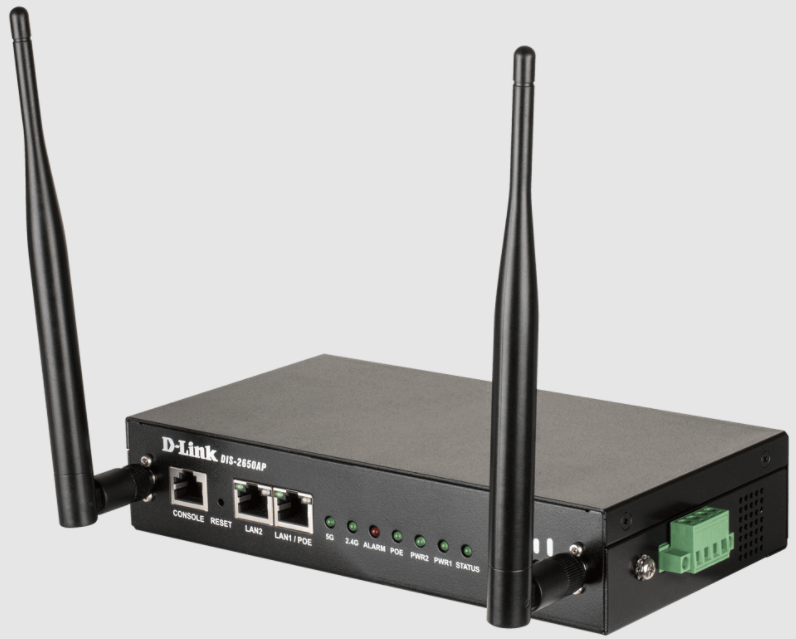
Hardware Overview
Front Panel Features


Side Panel Features


Hardware Installation
Before You Begin
Observe the following precautions to help prevent shutdowns, equipment failures, and personal injury:
- Install the DIS-2650AP in a cool and dry place.
- Install the DIS-2650AP in a site free from strong electromagnetic sources, vibration, dust, excessive moisture, and direct sunlight.
- Place antennas in an unobstructed area with a clear signal. Avoid metal boxes, brick walls, and other dense materials.
- Visually inspect the power connector and make sure that it is fully secure.
- Do not stack any devices on top of the DIS-2650AP.
Attach the External Antennas
The DIS-2650AP requires two external antennas to function correctly. The included antennas are interchangeable
- Attach the two included antennas to the RP-SMA connectors on the side of the DIS-2650AP. Turn clockwise to fasten the antennas.
- Arrange the antennas so that they’re pointing upwards and in a configuration to receive optimal signals.
Mounting the Device on a Wall
The DIS-2650AP can be installed on a solid surface by using the included wall mounting plates attached to the back of the device. Use the following instructions to install the DIS-2650AP on a wall:
- Align the cross-section of the mounting plates with the openings on the back of the device. Secure the plates with the included mounting screws.
- Remove the DIN rail mounting clip from the back of the device (if present).
- Place the mounting brackets (attached to the device) on the location where you want to mount it, and use the brackets as a guide to mark where to drill the screw holes.
- Drill holes on the marks and insert wall anchors appropriate for the material of the wall.
- Align the device with the wall anchors and secure it to the wall using appropriate screws for the wall anchors.

Installing the Device on a DIN Rail
The DIS-2650AP can be mounted on a standard DIN rail using the included DIN mounting kit. Use the following instructions to install the DIS-2650AP on a rail:
- Check that the DIN rail is installed properly using at least two screws on each end.
- Fasten the DIN mounting clip to the rear panel of the device using the included mounting screws.
- Position the DIS-2650AP against the rail, then tilt it upwards and hook the DIN rail clip on the back of the device against the rail. Snap the device into place to complete the installation.

Installing the Device into a Rack
The DIS-2650AP can be mounted on a standard rack using the included mounting plates. To install the device on a rack:
- Attach the mounting brackets to the rear panel of the device using the provided installation screws.
- Use the provided screws to attach the two rear mounting plates to the rack.

Grounding the Device
To use the DIS-2650AP safely, it needs to be grounded. Please complete these steps before powering on the device.
- Remove the grounding screw from the top of the DIS-2650AP and place the grounding cable lug ring on top of the grounding screw opening.
- Insert the grounding screw back into the grounding screw opening and use a screwdriver to tighten the grounding screw, securing the grounding cable to the DIS-2650AP.
- Attach the terminal lug ring at the other end of the grounding cable to an appropriate grounding source.
Powering the Device
The DIS-2650AP can be powered with an 802.3at PoE source or by using the built-in terminal adapter. This allows dual power inputs using wires from the power source(s) to be screwed into the terminal connections.
Using the Terminal Connections
- Before continuing, consult the diagram below to decide which wires from the power source need to connect to which contacts on the terminal block. Note that two power sources can be used; one inserted into V1-/V1+ (labeled PWR 1) and the other inserted into V2-/V2+ (labeled PWR2).
- Use a lever to remove the terminal block from the switch.
- Use a flat head screwdriver to unscrew the terminal connections that you wish to use.
- Insert the wires into the terminal connectiosn and use the screwdriver to tighten the screws to secure the wires.
- Re-insert the terminal block into the socket on the device.


Connecting Devices
The Ethernet port can be connected to an end device. Use a standard Category 5/5e/6 RJ-45 Ethernet cable to connect the end device to the DIS-2650AP.
The port will auto-negotiate to the highest possible port speed based on the connected device.
Management Options
The DIS-2650AP can be managed by using the Web User Interface (Web UI), the Nuclias Connect app, or the console port or Telnet management interfaces.
Nuclias Connect App Configuration
- Download the free Nuclias Connect app from the App Store or Google Play by searching for Nuclias Connect or by scanning the QR code below.
- Open the Nuclias Connect app and follow the onscreen instructions to discover and set up your device.

Manual Configuration
Note: The management computer, DHCP server and DIS-2650AP must be in the same subnet.
Use one of the following methods to access the web user interface:
Connecting through Ethernet
- Use an Ethernet cable to connect the DIS-2650AP to the management computer, or to the switch or router the management computer is connected to.
- Manage the access point from a computer. Enter dis2650ap.local in the address field of your browser.
- Log in to the administration user interface. The default information is:
- Username: admin
- Password: admin
Connecting Wirelessly
- Connect the management computer to the default SSID of the DIS-2650AP, “dlink.”
- Manage the access point from a computer. Enter dis2650ap.local in the address field of your browser.
- Log in to the administration user interface. The default information is:
- Username: admin
- Password: admin
Additional Information
If you are encountering problems setting up your network, please refer to the user manual.
Additional help is available online. To find out more about D-Link products or marketing information, please visit the D-Link support website at http://dlink.com/support/
Warranty Information
The D-Link Limited Lifetime Warranty information is available at the following website: http://warranty.dlink.com/
Appendix – Statements
ErP Power Usage
This device is an Energy Related Product (ErP) that automatically switches to a power-saving Network Standby mode within 1 minute of no packets being transmitted. It can also be turned off t hrough a power switch to save energy when it is not needed.
Network Standby: 3.12 watts
Federal Communication Commission Interference Statement
This equipment has been tested and found to comply with the limits for a Class B digital device, pursuant to Part 15 of the FCC Rules. These limits are designed to provide reasonable protection against harmful interference in a residential installation. This equipment generates, uses and can radiate radio frequency energy and, if not installed and used in accordance with the instructions, may cause harmful interference to radio communications. However, there is no guarantee that interference will not occur in a particular installation. If this equipment does cause harmful interference to radio or television reception, which can be determined by turning the equipment off and on, the user is encouraged to try to correct the interference by one of the following measures:
- Reorient or relocate the receiving antenna.
- Increase the separation between the equipment and receiver.
- Connect the equipment into an outlet on a circuit different from that to which the receiver is connected.
- Consult the dealer or an experienced radio/TV technician for help.
Non-modifications Statement:
Any changes or modifications not expressly approved by the party responsible for compliance
could void the user’s authority to operate this equipment.
Caution: This device complies with Part 15 of the FCC Rules. Operation is subject to the following two conditions:
- This device may not cause harmful interference, and
- this device must accept any interference received, including interference that may cause undesired operation.
This device and its antenna(s) must not be co-located or operating in conjunction with any other antenna or transmitter except in accordance with FCC multi-transmitter product procedures. For product available in the USA/Canada market, only channel 1~11 can be operated. Selection of other channels is not possible.
Note
The country code selection is for non-USA models only and is not available to all USA models. Per FCC
regulations, all WiFi product marketed in the USA must be fixed to USA operational channels only.
Radiation Exposure Statement:
This equipment complies with FCC radiation exposure limits set forth for an uncontrolled environment. This equipment should be installed and operated with minimum distance 20cm between the radiator & your bo
RF Frequency Requirements
This device is for indoor use only when using all channels in the 5.15 to 5.25 GHz frequency range. High power radars are allocated as primary users of the 5.25 to 5.35 GHz and 5.65 to 5.85 GHz bands. These radar stations can cause interference with and/or damage this device. This device will not operate on channels which overlap the 5600-5650 MHz band. It is restricted to indoor environments only.
IMPORTANT NOTICE:
Innovation, Science and Economic Development Canada (ISED) Statement: This Class B digital apparatus complies with Canadian ICES-003.
This device complies with ISED licence-exempt RSS standard(s). Operation is subject to the following two conditions:
- this device may not cause interference, and
- this device must accept any interference, including interference that may cause undesired operation of the device.
The device for operation in the band 5150-5250 MHz is only for indoor use to reduce the potential f or harmful interference to co-channel mobile satellite systems;
Operations in the 5.25-5.35 GHz band are restricted to indoor usage only.
Radiation Exposure Statement
This equipment complies with ISED radiation exposure limits set forth for an uncontrolled environment. This equipment should be installed and operated with minimum distance 20 cm between the radiator and your body.
Japan Voluntary Control Council for Interference Statement
This is a Class B product based on the standard of the VCCI Council. If this is used near a radio or television receiver in a domestic environment, it may cause radio interference. Install and use the equipment according to the instruction manual.
Product and Warranty Information
To find out more about D-Link Nuclias product or marketing information, please visit the website http://www.dlink.com or https://www.nuclias.com
The D-Link Limited Lifetime Warranty information is available at http://www.dlink.com/warranty
Industry Canada statement:
This device complies with ISED’s licence-exempt RSSs. Operation is subject to the following two conditions: (1) This device may not cause harmful interference, and (2) this device must accept any interference received, including interference t hat may cause undesired operation.
Caution :
- the device for operation in the band 5150-5250 MHz is only for indoor use to reduce the potential for harmful interference to co-channel mobile satellite systems;
- where applicable, antenna type(s), antenna models(s), and worst-case tilt angle(s) necessary to remain compliant with the e.i.r.p. elevation mask requirement set forth in section 6.2.2.3 shall be clearly indicated.