Wolf 808137 Sealed Burner Rangetop Installation Guide
808137 Sealed Burner Rangetop
Installation Guide
INSTALLATION INFORMATION
This section of the manual covers some of the installation issues that a service technician may need to know when
servicing a Wolf Sealed Rangetop. If additional installation information is needed after reviewing this section of the manual, please refer to the Installation Guide or contact the Wolf Appliance Customer Service Department.
WARNING
A SHOCK HAZARD COULD EXIST IF THE ELECTRIC RECEPTACLE OR THE POWER CORD ARE NOT PROPERLY GROUNDED AND POLARIZED.
CAUTION
The appliance may experience ignition problems if not properly grounded and polarized.
Electrical Requirements
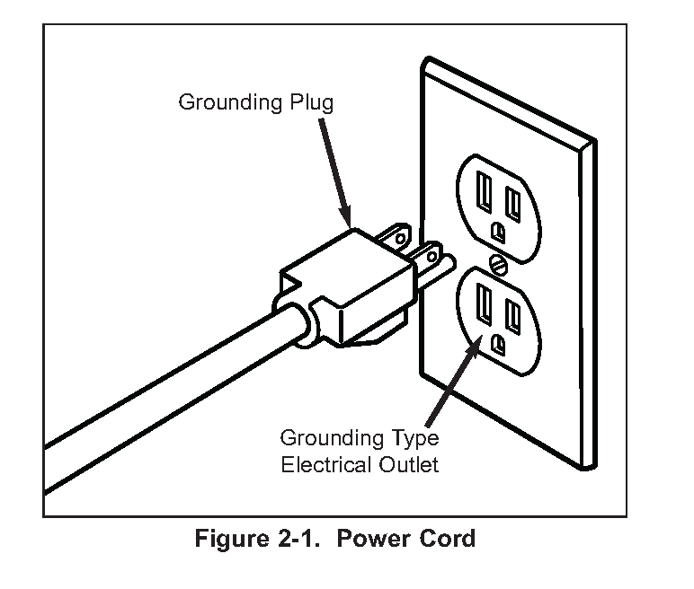
The Wolf sealed burner Rangetop produced for the United States requires a 110/120 V AC electrical supply to operate the electronic ignition system. The 6′ (1.8 m) power supply cord provided with the rangetop is equipped with a 3-prong, grounded plug for protection against shock hazard. The service should have its own 15 amp circuit breaker.
NOTES:
- You must follow all National Electrical Code and gas regulations. In addition, be aware of local codes and ordinances when installing your services.
- This appliance must be properly grounded to avoid shock hazard.
The Rangetop is equipped with a 3-prong ground plug. To minimize possible shock hazard, the cord must be
plugged into a mating 3-prong ground-type outlet, grounded to conform with the National Electrical Code,
ANSI/NFPA 70 latest edition, or Canadian Electrical Code (CSA) and all local codes and ordinances. Refer to the
illustration below.
NOTES:
- You must have a properly grounded, 3-prong outlet installed by a qualified electrician. A ground fault circuit interrupter (GFCI) is not recommended and may cause interruption of operation.
- Do not ground to a gas pipe.

Gas Requirements
Wolf Sealed Rangetop is manufactured to work with natural gas or LP gas (Liquid Propane gas). model / serial rating plate, located on the bottom of the control panel assembly on the far right, has information on the type of gas that should be used. If this information does not agree with the type of gas available, check with the local gas supplier.
Natural Gas Manifold Pressure
Standard natural gas orifices on the appliance are set for 5” WC (Water Column Pressure).
Liquid Propane Manifold Pressure
The standard propane gas orifices on the appliance are set for 10” WC (Water Column Pressure).
Gas Supply Line Size
- 3/4 inch rigid pipe to the range location
- For LP gas, piping or tubing size can be 1/2″ minimum.
NOTE: A smaller size pipe on long runs may result in insufficient gas supply.
A CSA design-certified, 3-foot long, 1/2″ or 3/4″ ID, flexible metal appliance connector is recommended for connecting this range to the gas supply line.
CAUTION
Do not kink or damage the connector when moving the range
Gas Supply Pressure for Domestic Units
- Maximum line pressure for natural gas and LP is 14” WC; 1/2 psi (3.5 kPa).
- Minimum line pressure for natural gas is 7” WC.
- Minimum line pressure for LP gas is 11” WC.
ICB units are CE certified for the following gas type and pressure:
- I3P – G31 at 37 mbar
- I2E – G20 at 20 mbar
- I2E+ – G20/25 at 20/25 mbar
- I2H – G20 at 20 mbar
CAUTION
The maximum gas supply pressure to the regulator should never exceed 14” WC (Water Column Pressure);
1/2 psi (3.5kPa)
Gas Pressure Regulator
To control and maintain a uniform gas pressure in the gas manifold, Wolf gas appliances must be connected to the
gas supply line through a pressure regulator. The burner orifices are sized for the pressure delivered by the regulator.
Never attempt to operate a Wolf gas appliance without the use of the proper pressure regulator
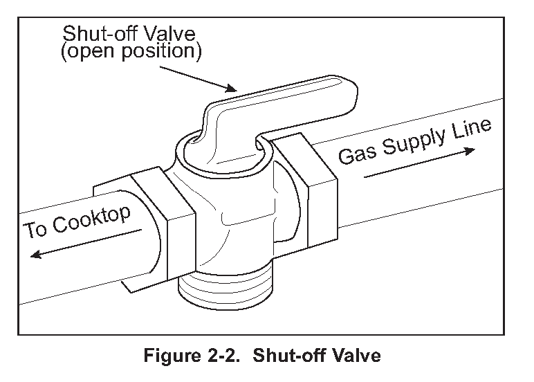
Gas Shut-off Valve
The supply line must be equipped with an approved shut-off valve. This valve should be located in accordance to all national, local codes and ordinances (See Figure 2-2).

Leak Testing
Use a brush and liquid detergent to test all gas connections for leaks. Bubbles around connections will indicate a leak. If a leak appears, shut off gas valve controls and adjust connections. Then check connections again.
Clean all the detergent solution from the range.
An electronic leak detector can also be utilized to test for leaks.
WARNING
NEVER USE OPEN FLAMES TO CHECK FOR GAS LEAKS. DO NOT USE LIQUID NEAR VALVE STEMS.
Supply Line Connection
All connections must be wrench-tightened. Do not make connections to gas piping too tight. Making the connection too tight may crack regulator and cause a gas leak. Do not allow pipes to turn when tightening fittings, tubing in the burner box may also bend and begin to leak.
Assemble flexible metal connector from gas supply pipe to pressure regulator. Determine fittings required, depending on size of gas supply line, flexible metal connector and shut-off valve (See Figure 2-3).
Use a pipe-joint compound made for use with natural and LP gas. If flexible metal connector is used, be sure tubing is not kinked.

Installation Dimensions – 30” Sealed Rangetop

NOTE: Island Installation: 12″ (305mm) minimum clearance from back of Rangetop to combustible rear wall above countertop, 0” (0mm) to non-combustible materials
Installation Dimensions – 36” Sealed Rangetop

NOTE: Island Installation: 12″ (305mm) minimum clearance from back of Rangetop to combustible rear wall above countertop, 0” (0mm) to non-combustible materials
Installation Dimensions – 48” Sealed Rangetop

Principals of Gas Combustion:
Combustion
When oxygen acts with a substance to produce large amounts of heat rapidly.
Requirements for Combustion
There are three required elements for combustion to occur; Fuel (Gas), Oxygen (Air) and Heat (Ignition
Temperature, which for gas is between 1100°F/593°C and 1200°F/649°C). All must be present. Removing any one of the three and combustion will cease.
Chemistry of Combustion
Combustion of gas is a chemical reaction between fuel gas and oxygen. The basic elements of common fuel
gasses are hydrogen [H] and carbon [C]. When hydrogen burns, water vapor [H2O] is produced. Complete burning of carbon in fuel gases form carbon dioxide [CO2] and water vapor [H2O].
Controlled Combustion
Controlled combustion takes place when gas and air are supplied at proper rates to assure complete combustion of
the gas in a steady flame. When a gas appliance is operating properly, burning starts at the burner ports. Gas flow
is controlled by gas orifice size and gas pressure upstream of the orifice. Air is mixed with the gas before it passes
through the burner ports. This added air is called “Primary Air”. The remaining air required for complete combustion is supplied to the burner at the point of combustion and is called “Secondary air”.
Adjustments of the gas-to-air ratio and the secondary air supply is the key to obtaining stable blue flames at a burner.
Proper amounts of primary and secondary air are required for quiet and efficient burner operation and for complete combustion of the gas. Air Shutters or other devices provide control of primary air. Inlet opening and flue outlets control Secondary Air flow.
Total air
In an ideal situation, primary and secondary air is all that is needed (for the oxygen required) to burn the gas, but
some additional air is required to assure complete burning of the gas. The total air, “primary”, “secondary” and
“excess” are expressed as percentages of the amount needed. About ten cubic feet of air is required to completely
burn one cubic foot of gas. For this reason an appliance should not be operated in an air tight home.
Limits of Flammability
Not all air-to-gas mixtures will burn. Mixtures with 0% – 4% natural gas in air are too lean to burn. Mixtures of 4% – 14% natural gas in air can burn with a controlled flame. Flammability limits come into play when primary air adjustments are made on burners. If too much primary air is used, the mixture may become too lean and fall below flammability limits, thus preventing combustion.
Incomplete Combustion (Causes and Effects)
To obtain complete combustion, sufficient amounts of air must be supplied to the process. This air must have a reasonably normal oxygen content. Complete burning of gas produces harmless carbon dioxide gas and water vapor.
If the air supply is insufficient, incomplete combustion occurs resulting in the formation of toxic by-products, such as carbon monoxide [CO] or aldehydes.
Carbon monoxide is colorless and odorless. Inhaling carbon monoxide in sufficient quantities could cause death by reducing oxygen levels in the blood.
Aldehydes, which are equally dangerous, have a sharp and penetrating odor which is easily detected by smell at
very low concentrations. The odor caused by aldehydes should not be confused with odorants added to natural gas.
The absence of aldehydes does not assure that carbon monoxide is not present. However, if the odor of aldehydes
is present, then carbon monoxide is virtually always present.
Gas Burner Operation
A gas burner is a device to burn gas under control in order to produce useful heat. Primary air is brought into the
burner from outside of the appliance at atmospheric pressure. The gas jet streaming from the orifice draws primary air with it into the burner.
The gas/air mixture, combined with a spark at the burner port(s) and the secondary air creates a controlled burn.