Motorola RLN6434 Travel Charger User Guide
TRAVEL CHARGER
RLN6434
USER GUIDE


IMPORTANT SAFETY INSTRUCTIONS
SAVE THESE INSTRUCTIONS
This document contains important safety and operating instructions. Please read these instructions carefully and save them for future reference.
Before using the battery charger, read all the instructions and cautionary markings on (1) the charger, (2) the battery, and (3) the radio using the battery.

- To reduce risk of injury during sudden braking or impact while driving, secure the Travel Charger and radio in the mounted bracket with the elastic strap securely fastened.
- To reduce risk of injury, charge only the rechargeable Motorola Solutions authorized batteries listed in Table 1. Other batteries may explode, causing personal injury and damage.
- Use of accessories not recommended by Motorola Solutions may result in risk of fire, electric shock, or injury.
- To reduce the risk of damage to the electric plug and cord, pull by the plug rather than by the cord when disconnecting the charger.
- To reduce risk of fire, electric shock, or injury, do not operate the charger if it has been broken or damaged in any way. Take it to a qualified Motorola Solutions service representative.
- Do not disassemble the charger; it is not repairable and replacement parts are not available. Disassembly of the charger may result in risk of electrical shock or fire.
OPERATIONAL SAFETY GUIDELINES
- This equipment is not suitable for outdoor use. Use only in dry locations/conditions.
- Connect equipment only to an appropriately fused and wired supply of the correct voltage (as specified on the product).
- When not in use, disconnect the power supply cord from the DC outlet.
- The equipment shall be connected to a nearby and easily accessible socket outlet.
- In equipment using fuses, replacements must comply with the type and rating specified in the equipment instructions.
- When used as a desktop charger, maximum ambient temperature around the power supply equipment must not exceed 40 °C (104 °F).
- Output power from the power supply unit must not exceed the ratings stated on the product label located on the bottom of the charger.
- Make sure the cord is located where it cannot be stepped on, tripped over, or subjected to water, damage, or stress.
- To reduce risk of damage to vehicular charger adapter and cord, pull by the vehicular charger adapter rather than the cord when disconnecting the charger.
- Do not operate the charger or vehicular charger adapter with a damaged cord. Replace it immediately.
Vehicles Equipped with Air Bags
- Do not place or install equipment in the area over an air bag or in the air bag deployment area. Air bags inflate with great force. If equipment is installed in the air bag deployment area and the air bag inflates, the equipment may be propelled with great force and cause serious injury to occupants of the vehicle.
- If the communication equipment is improperly installed and the air bag inflates, this could cause serious injury.
- Installation of vehicle communication equipment should be performed by a professional installer/technician qualified in the requirements for such installations. An air bag’s size, shape and deployment area can vary by vehicle make, model and front compartment configuration (e.g. bench seat vs. bucket seats).
- Contact the vehicle manufacturer’s corporate headquarters, if necessary, for specific air bag information for the vehicle make, model and front compartment configuration involved in your communication equipment installation.
- If mounted on an insecure or hollow mounting surface, the bracket can loosen and the unit can break free on collision. Mount the bracket only in a location which allows the self-tapping screws to solidly anchor into a metal surface.
- The mounting screws can damage cables and wires that run under some mounting surfaces in the vehicle. Contact the vehicle manufacturer for the detailed locations of cables and wires in your vehicle, and avoid mounting the radio above those locations.
MOTOROLA SOLUTIONS AUTHORIZED BATTERIES
The batteries listed in Table 1 are approved for use with the RLN6434 Travel Charger kit.
Table 1. Motorola Solutions Authorized Batteries
| Kit Number | Description |
| NNTN7033 | IMPRES Li-Ion FM (HazLoc) IP67 4100 mAh |
| NNTN7034 | IMPRES Li-Ion IP67 4200 mAh |
| NNTN7035 | IMPRES NiMH FM (HazLoc) Ruggedized 2000 mAh |
| NNTN7036 | IMPRES NiMH FM (HazLoc) IP67 2000 mAh |
| NNTN7037 | IMPRES NiMH IP67 2100 mAh |
| NNTN7038 | IMPRES Li-Ion IP67 2900 mAh |
| NNTN7573 | IMPRES NiMH Ruggedized 2100 mAh |
| NNTN8092 | IMPRES Li-Ion FM (HazLoc) Ruggedized 2300 mAh |
| NNTN8182 | Li-Ion Ruggedized IP67 2900 mAh |
| NNTN8921 | IMPRES 2 Li-Ion TIA4950 (HazLoc) Ruggedized IP67 3700 mAh |
| NNTN8930 | IMPRES 2 Li-Ion TIA4950 (HazLoc) Ruggedized IP67 2700 mAh |
| PMNN4403 | IMPRES Li-Ion IP67 2150 mAh |
| PMNN4485 | IMPRES 2 Li-Ion Ruggedized IP67 2500 mAh |
| PMNN4486 | IMPRES 2 Li-Ion Ruggedized IP67 3400 mAh |
| PMNN4487 | IMPRES 2 Li-Ion Ruggedized IP67 4400 mAh |
| PMNN4494 | IMPRES 2 Li-Ion Ruggedized IP67 5000 mAh |
| PMNN4504 | IMPRES 2 Li-Ion DIVISION 2 (HazLoc) Ruggedized IP67 3400 mAh |
| PMNN4505 | IMPRES 2 Li-Ion DIVISION 2 (HazLoc) Ruggedized IP67 4850 mAh |
| PMNN4547 | IMPRES 2 Li-Ion TIA4950 (HazLoc) Ruggedized IP68 3100 mAh |
| PMNN4573 | IMPRES 2 Li-Ion TIA4950 (HazLoc) Ruggedized IP68 4600 mAh |
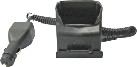
DESCRIPTION
The RLN6434 Travel Charger kit is used for charging a radio when inside a vehicle. The Travel Charger kit includes a vehicular charger adapter attached to a charger, and a mounting bracket to mount the Travel Charger inside the vehicle.
The Travel Charger has the capability to charge a stand alone battery or a radio with a battery.
OPERATING INSTRUCTIONS
The Travel Charger charges only the Motorola Solutions authorized battery listed in Table 1. Other batteries may not charge.
Your battery must first need to be charged using the rapid charge method before operating your radio for the first time.
Note: Do not leave a battery or radio in the Travel Charger for extended periods of time (1 week) in order to avoid a decrease in overall battery performance.


Charging Inside the Vehicle
- Plug the vehicular charger adapter into the vehicle auxiliary power outlet.
Note: Some vehicle auxiliary power outlets do not maintain an electrical current once the vehicle has been turned off. Rated input: 12 – 24 DC 1.2 A.
Charging the Battery
- Insert a battery or radio with a battery into the charger pocket, making sure the charging contacts make contact with the battery. The battery charging indicator LED on the charger indicates:
Table 2. Battery Charging Indicators
| Status | LED Status | Descriptions |
| Power On | Green for approximately 1 second | Successful charger power-up |
| Charging | Steady Red | Battery in rapid charge mode |
| 90% Charged | Blinking Green | Battery is charged to 90 % or greater capacity |
| Fully Charged | Steady Green | Battery is nearly charged or fully charged |
| Fault | Blinking Red | Remove and re-insert radio or battery |
| Standby | Blinking Amber | Battery is waiting to rapid charge. Battery may be too hot, too cold, or low voltage |
Mounting The Bracket
- Select a location for the bracket that does not interfere with vehicle operation or with the vehicle air bag deployment.
- Using the bracket as a template, mark the location of the three or four mounting holes using either the bottom or back mounting holes.
- Using a 5/32” (4 mm) diameter drill bit, drill the three or four holes.
- Using a 5/16” (8 mm) hex nut driver, secure the bracket using the three or four screws provided.
Securing the Travel Charger and radio into the Bracket
Motorola Solutions highly recommends securing the Travel Charger and radio into the mounting bracket when inside the vehicle. Sudden braking or impact can propel the Vehicle Charger or radio with great force and cause serious injury to occupants of the vehicle.
1. Insert the Travel Charger into the bracket at a downward angle (See illustration below).

2. Push the back of the Travel Charger into the bracket until it is securely in place.
3. Insert the radio into the Travel Charger.
Note: Some effort may be required in the insertion/ removal, as the charger is designed to firmly retain the battery/radio.
4. Extend the elastic cord and nylon strap between the channel select knob and the volume knob. Hook the clip under the front lip of the bracket.
| Do not cover emergency button with strap. |


Note: The charger is reversible to display either side of the radio when placed in the bracket.
MOTOROLA, MOTO, MOTOROLA SOLUTIONS and the Stylized M logo are trademarks or registered trademarks of Motorola Trademark Holdings, LLC and are used under license. All other trademarks are the property of their respective owners.
© 2011 and 2021 Motorola Solutions, Inc. All rights reserved.
Printed in


68012003023-BF