Yamaha RM-CR Signal Processor Instruction Manual

Instruction Manual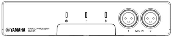


FCC INFORMATION (U.S.A.)
- IMPORTANT NOTICE:
DO NOT MODIFY THIS UNIT!
This product, when installed as indicated in the instructions contained in this manual, meets FCC requirements. Modifications not expressly approved by Yamaha may void your authority, granted by the FCC, to use the product. - IMPORTANT: When connecting this product to accessories and/or another product use only high-quality shielded cables. Cable/s supplied with this product MUST be used. Follow all installation instructions. Failure to follow instructions could void your FCC authorization to use this product in the USA.
- NOTE: This equipment has been tested and found to comply with the limits for a Class A digital device, pursuant to Part 15 of the FCC rules. These limits are designed to provide reasonable protection against harmful interference when the equipment is operated in a commercial environment. This equipment generates, uses, and can radiate radio frequency energy and, if not installed and used in accordance with the instruction manual, may cause harmful interference to radio communications. Operation of this equipment in a residential area is likely to cause harmful interference in which case the user will be required to correct the interference at his own expense.
COMPLIANCE INFORMATION STATEMENT
(Supplierʼs declaration of conformity procedure)
| Responsible Party: | Yamaha Unified Communications, Inc. |
| Address: | 144 North Rd, Suite 3250 Sudbury, MA 01776 |
| Telephone: | 800-326-1088 |
| Type of Equipment: | Signal Processor |
| Model Name: | RM-CR |
This device complies with Part 15 of the FCC Rules.
Operation is subject to the following conditions:
- this device may not cause harmful interference, and
- this device must accept any interference received including interference that may cause undesired operation.
PRECAUTIONS
PLEASE READ CAREFULLY BEFORE PROCEEDING
Please keep this manual in a safe place for future reference.
Yamaha cannot be held responsible for damage caused by improper use or modifications to the product, or data that is lost or destroyed.
Always follow the basic precautions listed below to avoid the possibility of serious injury or even death from electrical shock, short-circuiting, damages, fire, or other hazards. These precautions include, but are not limited to, the following:

Fire warning
- Do not place any burning items or open flames near the product, since they may cause a fire.
Hearing loss
- Before turning the power of all devices on or off, make sure that all volume levels are set to the minimum. Failing to do so may result in hearing loss, electric shock, or device damage.
- When turning on the AC power in your audio system, always turn on the power amplifier LAST, to avoid hearing loss and speaker damage. When turning the power off, the power amplifier should be turned off FIRST for the same reason.
Wireless unit
- Do not use this product near medical devices or inside medical facilities. Radio waves from this product may affect electro-medical devices.
- Do not use this product within 15 cm (6 in) of persons with a heart pacemaker implant or a defibrillator implant. Radio waves from this product may affect electro-medical devices, such as a heart pacemaker implant or defibrillator implant.
Always follow the basic precautions listed below to avoid the possibility of physical injury to you or others. These precautions include, but are not limited to, the following:
If you notice any abnormality
- If any of the following problems occur, immediately turn off the PoE injector or the PoE network switch and disconnect the cable.
– The LAN cable was damaged.
– Unusual smells or smoke is emitted.
– Some object or water has been dropped into the product.
– There is a sudden loss of sound during the use of the product.
– Cracks or other visible damage appear on the product.
Then have the product inspected or repaired by qualified Yamaha service personnel.
Location and connection
- When connecting this product with a PoE injector or the PoE network switch, use a CAT5e or higher LAN cable, which supports the maximum power supply voltage (57 V) of the IEEE 802.3at standard. If you connect a cable that does not comply with specifications or connect a flat type or slim type cable, fire or malfunctions might occur.
- Do not damage the LAN cable. Failure to observe this precaution could result in fire, electric shock, or damage to the product.
– Do not place heavy objects on the cable.
– Do not process the cable in any way.
– Do not use staples to fix the cable in place.
– Do not apply excessive force to the cable.
– Be sure to keep the cable away from anything hot. - Do not place the product in an unstable position or a location with excessive vibration, where it might accidentally fall over and cause injury.
- Keep this product out of reach of children. This product is not suitable for use in locations where children are likely to be present.
- Do not block the vents. This product has ventilation holes at the rear/sides to prevent the internal temperature from becoming too high. In particular, do not place the product on its side or upside down. Inadequate ventilation can result in overheating, possibly causing damage to the product(s), or even fire.
- When installing the product:
– Do not cover it with any cloth.
– Do not install it on a carpet or rug.
– Make sure the top surface faces up; do not install on its sides or upside down.
– Do not use the product in a confined, poorly-ventilated location.
Inadequate ventilation can result in overheating, possibly causing damage to the product(s), or even fire. - If the product is mounted in an EIA standard rack, carefully read the section “Please read before mounting the unit into a rack” on page 15. Inadequate ventilation can result in overheating, possibly causing damage to the product(s), malfunctioning, or even fire.
- Do not place the product in a location where it may come into contact with corrosive gases or salt air. Doing so may result in malfunction.
- Before moving the product, remove all connected cables.
- Do not route cables where someone might trip over them, such as in a location where people pass. Tripping on a cable may cause a person or this product to fall down, resulting in personal injury or damage to the product.
- Do not use the separately sold RM-MTL mounting accessory to attach the unit to a ceiling or wall that is higher than 2 meters. If the unit falls, injury or damage might occur.
- Always consult qualified Yamaha service personnel if the product installation requires construction work. Improper installation might cause accidents, injuries, damage or malfunction of this product.
Do not open
- This product contains no user-serviceable parts. Do not attempt to disassemble the internal parts or modify them in any way.
Water warning
- Do not expose the product to rain, use it near water or in damp or wet conditions, or place on it any containers (such as vases, bottles, or glasses) containing liquids that might spill into any openings.
- Never insert or remove a cable with wet hands.
Handling caution
- Do not insert your fingers or hands in any gaps or openings on the product (vents, etc.).
- Do not rest your weight on the product or place heavy objects on it.
Backup battery
- Do not replace the backup battery by yourself. Doing so may cause an explosion and/or damage to the product(s).
NOTICE
Handling and maintenance
- Do not connect this product to public Wi-Fi and/or Internet directly. Only connect this product to the Internet through a router with strong password protections. Consult your router manufacturer for information on security best practices.
- Do not use the product in the vicinity of a TV, radio, or other electric products. Otherwise, the product, TV, or radio may generate noise.
- Do not expose the product to excessive dust or vibration, or extreme cold or heat, in order to prevent the possibility of panel disfiguration, unstable operation, or damage to the internal components.
- Do not install in locations where temperature changes are severe. Otherwise, condensation may form on the inside or the surface of the product, causing it to break.
- If there is reason to believe that condensation might have occurred, leave the product for several hours without turning on the power until the condensation has completely dried out, in order to prevent possible damage.
- Do not place vinyl, plastic, or rubber objects on the product, since this might cause alteration or discoloration of the panel.
- When cleaning the product, use a dry and soft cloth. Do not use paint thinners, solvents, cleaning fluids, or chemical-impregnated wiping cloths, since this might cause alteration or discoloration.
- The rubber feet included in this package can be attached to the product to prevent slippage when it is to be used on a slippery surface.
INFORMATION
About functions/data bundled with the product
- This is a class A product. The operation of this product in a residential environment could cause radio interference.
- Refer to the website below for the licensing terms of the open-source software used in this product.
The U.S.A. and Canada https://uc.yamaha.com/support/ Other Countries https://download.yamaha.com/ - This product uses Dante Broadway.
Refer to the Audinate website (English) for details on the open-source licenses for the particular software. https://www.audinate.com/software-licensing - XLR-type connectors are wired as follows (IEC60268 standard): pin 1: ground, pin 2: hot (+), and pin 3: cold (-).

The Bluetooth® word mark and logos are registered trademarks owned by Bluetooth SIG, Inc. and any use of such marks by Yamaha Corporation is under license.
About this manual
- This Installation Manual uses the following signal words for the important information:
| This content indicates a “risk of serious injury or death.” | |
| This content indicates a “risk of injury.” | |
| NOTICE | Indicates content that you must observe in order to prevent the product from malfunctioning, being damaged, or operating incorrectly, and to avoid data loss. |
| IMPORTANT | Indicates content that you must know in order to operate and use the product correctly. |
| NOTE | Indicates information that is related to operation and use. Read this for your reference. |
- The illustrations as shown in this manual are for instructional purposes only.
- The company names and product names in this manual are the trademarks or registered trademarks of their respective companies.
- Software may be revised and updated without prior notice.
- The contents of this manual apply to the latest specifications as of the publishing date. To obtain the latest manual, access the Yamaha website then download the manual file.
About disposal
- This product contains recyclable components. When disposing of this product, please contact the appropriate local authorities.

Information for users on collection and disposal of old equipment:
For proper treatment, recovery, and recycling of old products, please take them to applicable collection points, in accordance with your national legislation.
By disposing of these products correctly, you will help to save valuable resources and prevent any potential negative effects on human health and the environment which could otherwise arise from inappropriate waste handling.
For more information about the collection and recycling of old products, please contact your local municipality, your waste disposal service or the point of sale where you purchased the items.
For business users in the European Union:
If you wish to discard electrical and electronic equipment, please contact your dealer or supplier for further information.
Information on Disposal in other Countries outside the European Union:
This symbol is only valid in the European Union. If you wish to discard these items, please contact your local authorities or dealer and ask for the correct method of disposal.

INTRODUCTION
Thank you for purchasing the RM-CR signal processor. This product is a signal processor that produces high-quality and pleasant audio for remote conferences held in medium-sized meeting rooms or offices. Be sure to read this manual before using the product. Please retain this manual in a safe location for future reference.
Included items
- Installation manual (this document)
- Access panel (with screw)
- USB cable (A-B type, 5 meters, for voice communication)
- USB cable (A-micro B type, 1 meter, for setup)
- Rubber feet (4 pcs.)
Separately sold items
- RM-MRK mounting accessory
This is required when installing the product in a 19-inch rack.
For details on attaching the RM-MRK, refer to “INSTALLATION IN A RACK” (page. 15). - RM-MTL mounting accessory
This is required when installing the product on the underside of a desk.
For details on attaching the RM-MTL, refer to “INSTALLATION ON A DESK” (page. 17).
Manual structure
Regarding this product, the following materials are available in addition to this installation manual.
- RM-CR reference manual
This explains connections between this device and external devices, and settings via the web UI.
Related documents can be downloaded from the following website.
The U.S.A. and Canada
https://uc.yamaha.com/support/
Other Countries
https://download.yamaha.com/
CONTROLS AND CONNECTORS
Front Panel
The explanation here uses an illustration depicting the state in which the product is shipped.
After you have made settings, use the screw to fasten the included access panel so that the [RESET] button and the [SETUP] port are inaccessible.
For details on each indicator, refer to the “RM-CR Reference Manual.”

This is the power supply indicator. It is lit when power is being correctly supplied to the rear panel [Dante/PoE] port.
This indicates the status of the unit.
Press to pair with a smartphone via Bluetooth.
By connecting to a smartphone, you can exchange audio with a remote location.- [MIC IN] 1/2 jacks
These are XLR jacks (balanced) for connecting dynamic mics. Do not connect condenser mics here. - [RESET] button
Use a fine-pointed object such as an eject pin to press this button.Long press Status indicator Reset target 4 seconds to less than 8
secondsFlashes twice per
secondNetwork-related settings 8 seconds to less than
12 secondsFlashes three times
per secondAll settings
(automatically restarts after initialization)Long-pressing this button for less than 4 seconds or for 12 seconds or more does not reset anything.
- [SETUP] port
This port is for connection to a computer so that settings can be made via a web
browser. Use the included USB cable (A-micro B type) for this connection. For details
on settings, refer to the “RM-CR Reference Manual.” - [AUX IN] L/R jacks
These are RCA jacks (unbalanced) for audio input. Use these jacks if the audio from the remote location is analog. - [AUX OUT] L/R jacks
These are RCA jacks (unbalanced) for audio output. Use these jacks if the audio to the remote location is analog. - Speaker jacks
These are RCA jacks (unbalanced) for audio output. Use these jacks if the powered speaker or power amp used in the remote location does not support Dante. - USB port
Use this port when connecting to a computer to exchange audio with a remote location.
Use the included USB cable (A-B type) for this connection. - Network ports
These are RJ-45 ports to which you can connect LAN cables (CAT5e or higher) for remote administration and settings via the company network, etc.
DHCP is specified by default. If you want to use a specific IP address, use the web UI to specify the IP address before connecting to the company network. For details on
settings, refer to “RM-CR Reference Manual.”
You can also connect to a public network for exchanging audio with a remote location via the SIP protocol.
Notice: The maximum usable cable length is 100 meters.
: To prevent electromagnetic interference, use STP (Shielded Twisted Pair) cables. - [Dante/PoE] port
This is an RJ-45 port to which you can connect a LAN cable (CAT5e or higher) via an IEEE802.3at compliant a PoE injector or the PoE network switch to a Dante unit such as the RM-CG.
Notice: Do not connect any device here other than a Dante-compatible device or a device (including a computer) that supports gigabit Ethernet.
: The maximum usable cable length is 100 meters.
: To prevent electromagnetic interference, use an STP (Shielded Twisted Pair) cable. - Exhaust vent
This product is equipped with a cooling fan. Hot air is exhausted from this vent, so take care that the vent is not blocked by any obstruction. - Intake vent
Cooling air is taken in through this vent, so take care that the vent is not blocked by any obstruction. You should also clean this vent periodically. If dust accumulates on this vent, the temperature inside the unit might rise, causing the unit does not operate normally. - Mounting accessory attachment holes
Use these when attaching the RM-MRK or RM-MTL mounting accessory.
For details on attaching the RM-MRK, refer to “INSTALLATION IN A RACK” (page. 15).
For details on attaching the RM-MTL, refer to “INSTALLATION ON A DESK” (page. 17). - Rubber foot attachment guides
These are the locations at which to attach the included rubber feet. Attach the included rubber feet as shown in the illustration. - Product label
This shows the model name, serial number, and MAC address of this unit.


Rear panel

Side panel
This explanation uses an illustration of the left side as seen from the front.

Bottom panel


INSTALLATION IN A RACK
Use the separately sold RM-MRK mounting accessory to install the unit.
Please read before mounting the unit into a rack
This product is warranted to operate in a temperature range of 0–40°C. If this product is mounted in a rack together with other devices, there might be cases in which heat from the various devices causes the temperature inside the rack to rise, so that the product is unable to perform satisfactorily. To prevent the temperature inside the unit from rising, mount the unit in the rack in accordance with the requirements below.
- If this product is mounted together with devices that are prone to produce heat, such as power amps, leave at least 1U of space between it and other devices. Also, be sure to maintain sufficient ventilation in this space by installing a ventilation panel or leaving it open.
- Leave the rear panel of the rack open, and ensure that the rack is at least 10 cm away from the wall or ceiling to allow sufficient air circulation. If you cannot open the rear panel of the rack, install a commercially-available forced ventilation device, such as a fan kit. If you install a fan kit, closing the rear panel may work better for heat dissipation purposes.
For more information, refer to the owner’s manual for the rack and/or fan kit.
If this product is moved while mounted in a rack, vibration, etc. might cause the mounting accessory to deform or break, possibly causing injury. There is also a possibility that this unit might malfunction.
[Installation]
The example shown here is for when the long metal fixture is attached to the left side as seen from the front. The procedure can also be used when attaching the long metal fixture to the opposite side.
Notice: If the included rubber feet have already been attached to the unit, remove them.
- When attaching each metal fixture, place the spacer sheet included between this unit and the metal fixture.
Using the attachment screws (4 pcs.) included with the mounting accessory, fasten a metal fixture to each side of this unit.
If the unit falls, injury or damage might occur. This could also cause electric shock or malfunctions. - Attach the metal fixtures to the 19-inch rack.
Attach the metal fixtures to the 19-inch rack using the four included attachment screws of the rack. Be sure to tighten the screws so that they will not get loosened.


INSTALLATION ON A DESK
Use the separately sold RM-MTL mounting accessory to install the unit.
Obtain four screws with a diameter of approximately 5 mm (M5 equivalent) that are appropriate for the material and thickness of the desktop.
Carry out the installation through step 4.
If the unit falls, injury or damage might occur.
Caution: Installation must be performed by a qualified installer. During installation, pay attention to the following points.
- Choose hardware and a location that is well able to support the weight of this unit
- Avoid locations that are subject to sustained vibration
- You must use the specified installation accessory
- Perform periodic maintenance checks
- Using four commercially available screws approximately 5 mm in diameter, fasten the metal fixture to the underside of the desktop.
If the unit falls, injury or damage might occur. - Provisionally install the two included screws into the front holes of the mounting accessory attachment holes of this product.
When doing so, leave a gap of approximately 2 mm between the side of the unit and the head of the screw, so that the screws can engage the metal fixture. - Slide the unit so that the screws you provisionally installed in step 2 engage the slots of the metal fixture attached under the desk.
- Tighten the four screws in the attachment holes of the mounting accessory.


MAIN SPECIFICATIONS
General specifications
| Dimensions | W215 mm x D264 mm x H44 mm | |
| Weight | 1.6 kg | |
| Power supply | PoE+ (IEEE802.3at, LLDP), DC 48 V | |
| Maximum power consumption | 15.0 W | |
| Temperature | Operating | 0 °C – 40 °C |
| Storage | -20 °C – 60 °C | |
| Humidity | Operating | 30% – 90% (non-condensing) |
| Storage | 20% – 90% (non-condensing) | |
| Indicators | •Power •Status •Bluetooth •Network Port Indicator (x3) | |
| Included items | Installation manual (this document), access panel (with screw), USB cable (A-B type), USB cable (A-micro B type), rubber feet (4 pcs.) | |
| Separately sold items | Mounting accessory: RM-MTL Mounting accessory: RM-MRK | |
Audio specifications
| Frequency response | 20 Hz – 20 kHz | ||
| Sampling rate | 48 kHz | ||
| Bit depth | 24-bit | ||
| Latency | 8 [ms] (Dante In to USB Out, including signal processing) | ||
| Audio interface | Dante | 16 in x 16 out | |
| USB | USB2.0 type-B, Audio Class 1.0 Input: 2ch, Output: 2ch @48 kHz | ||
| Mic Input | XLR balanced, Input 2ch | ||
| AUX | RCA unbalanced (Line Level), Input: 2ch, Output: 2ch | ||
| Speaker Out | RCA unbalanced (Line Level), Output: 2ch | ||
| Bluetooth | Version 4.2 Supported protocols: HFP (1.6), A2DP, AVRCP (1.6) Supported codecs: CVSD, SBC, mSBC Wireless output: Class 2 Maximum communication distance: 10 meters (no obstructions) Wireless frequencies (operating frequencies): 2,402 – 2,480 MHz Maximum output power (EIRP): 4.0 dBm (2.5 mW) | ||
| SIP | Call Handling | Dial, Answer, Hold, Resume, Forwarding, Do not disturb, Call-ID, Voice Mail Notifications (switch configured) | |
| Call Bridging | Supports Bridging SIP, USB, BT, and AUX Calls. Join, Split, Hold, Resume, 5+1 Lines: Up to 2 SIP calls, 1 USB call, 1 Bluetooth call, 1 AUX, plus the user | ||
| Codecs | G.711, G.722HD, G.729ab, G.726 | ||
| DTMF Support | RTP event, SIP in-band, SIP info package | ||
| Security | SRTP Support (RFC 1889), IETF SIP support (RFC 3261 and companion RFCs) | ||
Network specifications
| [Dante/PoE] port | Dante Audio/Dante Control, remote control, WebUI, PoE+ supported Cable requirements: CAT5e or higher, STP |
| Network ports | Corporate Network, remote control, SIP, WebUI Cable requirements: CAT5e or higher, STP |
| [SETUP] port | USB2.0 micro, Network Class, WebUI, fixed IP Cable requirement: USB cable (A-micro B type) |
Input/output characteristics
| Input
Terminal |
Actual Load
Impedance |
For Use With
Nominal |
Input Level | Connector | |
| Nominal | Max.
Before Clip | ||||
| MIC IN | 2.2 kΩ | 1Balanced) 50 – 600 0 | -46 dBu | -26dBu | XLR-3-31 |
| AUX IN L, R |
20 kΩ | 1 ka | -14 dBV | +6 dBV | RCA PIN |
| Output
Terminal |
Actual Source
Impedance |
For Use With
Nominal |
Output Level | Connector | |
| Nominal | Max.
Before Clip | ||||
| AUX OUT L, R |
1kΩ | 10kΩ | −14dBV | +6dBV | RCA PIN |
| SP OUT L, R |
1kΩ | 10kΩ | −14dBV | +6dBV | RCA PIN |
Dimensional diagram

Yamaha Global Site The U.S.A. and Canada
https://uc.yamaha.com/
Other Countries
https://www.yamaha.com/
Yamaha Downloads The U.S.A. and Canada
https://uc.yamaha.com/support/
Other Countries
https://download.yamaha.com/
Manual Development Group
© 2020 Yamaha Corporation
Published 12/2020
IPES-C0