Honeywell POSI3 USB Flow Test Units User Guide


Honeywell POSI3 USB Flow Test Units

Quick Start Guide Overview
This Quick Start Guide is designed to help you install your Posi3 USB with basic options that apply to most users for first time use using a Windows 32/64bit PC
(Windows XP to Windows 7 operating system). For advanced installations please refer to either the included Setup Guide or the help file by pressing F1 at any time during installation.
Table of Contents
- Posi3 USB Components
- Software Installation
- Database Set Up
- Hardware Set Up
- User Set Up
- Adding SBCA Models
- Testing
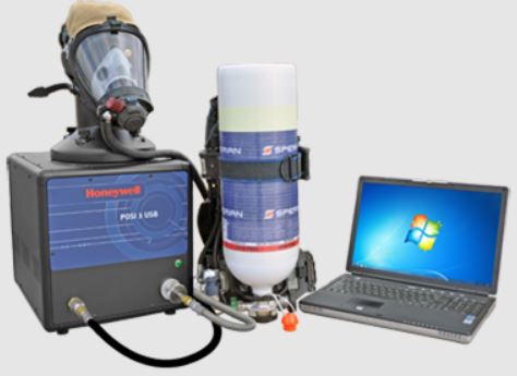
Posi3 USB Components
Unpack the Posi3 USB and accessories and verify that all parts are present. Do not discard the shipping cartons and packing materials – they are necessary for returning the Posi3 USB to Honeywell Analytics for its annual calibration.

- Posi3 USB
- Head Assembly
- Tygon tube
- Low-Pressure Manifold*
- High-Pressure Manifold*
- First Stage Manifold*
- Head Gasket
- 4 Standoffs
- 4 Tightening Knobs
- CD-ROM
- Setup Guide
- Quick Start Guide
- USB Cable
- Power Cable
- 3 High-Pressure Manifold Replacement O-Rings*
- 3 Low-Pressure Manifold Replacement O-Rings*
- High Pressure Manifold Replacement Hex-Head Screw*
- Spare Fuse (2)
Not included with European model.
Basic Software Installation
All POSI3 USB software end users must have permission to modify the following areas of the PC:
- The registry section
HKEY_LOCAL_MACHINE\SOFTWARE\Sperian\Pos i3 USB and all its subsections. - The folder location C:\Program
Files\Sperian\Posi3USB and all its subfolders.
It may be necessary to contact your IT department so they can provide you with the necessary access.
Note on Brand-Specific Software: If you are planning to service a specific brand of SCBA, make sure you have the OEM Posi3 USB software for that brand.
- To install your POSI3 USB software, if having a CD, insert the CD-ROM. If the software fails to launch automatically, use Windows Explorer to navigate to the CD-ROM drive and run BATestSetup.exe. If having a downloaded file, be sure to have the BATestSetup.exe and the License.exe applications in the same folder.
- It is recommended to exit any other Windows programs that may be running and verify the License information and End User License Agreement.
- By default, the software is installed to C:\Program Files (x86)\Sperian\Posi3USB\Standard\BATest.
- Follow the screen prompts to continue installation with default settings.

Database Setup
The Database Installation Wizard is automatically launched near the end of the software installation.
- First time installation requires the installation of the PostgreSQL Server.
(For advanced installation or connecting to an existing server, please refer to the included Setup Guide or Help File by pressing F1 at any time)
Note: Administrator-level system access is required to install the PostgreSQL database server.
In some versions of Windows, you may need to click “OK” to proceed. - Choose the Basic Installation and click “Install”
- The PostgreSQL installation will begin automatically.
A separate application is used to install the server. F1 help is not available in the database installation application.
Do not continue with the Database Installation Wizard until the database server installation is complete. - When you are back at the Database Installation Wizard, click “Next” to install the model’s database.
- The Database Installation Wizard will automatically choose the location, port to use, as well the Server Owner Name and Password (biosystems).
- Select “Install a NEW test results database” and click “Next”.
- Type in a name for the test results database (Special characters and spaces are not allowed). Click OK.
- Click the Finish button to exit the Database Installation Wizard.
- For Windows 7 or above, restarting the PC is optional.


Advanced Software Installation
All POSI3 USB software end users must have permission to modify the following areas of the PC:
- The registry section
HKEY_LOCAL_MACHINE\SOFTWARE\Sperian\Pos i3 USB and all its subsections. - The folder location C:\Program
Files\Sperian\Posi3USB and all its subfolders.
It may be necessary to contact your IT department so they can provide you with the necessary access.
Note on Brand-Specific Software: If you are planning to service a specific brand of SCBA, make sure you have the OEM Posi3 USB software for that brand.
- To install your POSI3 USB software, if having a CD, insert the CD-ROM. If the software fails to launch automatically, use Windows Explorer to navigate to the CD-ROM drive and run BATestSetup.exe. If having a downloaded file, be sure to have the BATestSetup.exe and the License.exe applications in the same folder.
- It is recommended to exit any other Windows programs that may be running and verify the License information and End User License Agreement.
- By default, the software is installed to C:\Program Files (x86)\Sperian\Posi3USB\Standard\BATest.
- Follow the screen prompts to continue installation with default settings.

Database Setup
The Database Installation Wizard is automatically launched near the end of the software installation.
- First time installation requires the installation of the PostgreSQL Server.
(For advanced installation or connecting to an existing server, please refer to the included Setup Guide or Help File by pressing F1 at any time)
Note: Administrator-level system access is required to install the PostgreSQL database server. - Choose the Advanced Installation and click “Install”
- The PostgreSQL installation will begin automatically.
A separate application is used to install the server. F1 help is not available in the database installation application.
Do not continue with the Database Installation Wizard until the database server installation is complete. - PostgreSQL Welcome screen will be shown; click Next.
- Select the Install directory. By default,C:\Program Files\PostgreSQL\10. Click Next.
- Select all components to be installed
- Select the Data directory. By default,C:\Program Files\PostgreSQL\10\data. Click Next.
Note: If for any reason the Data is needed in a different path, contact Honeywell Tech Support for assistance. - 8. Assign a User and Password for the PostgreSQL Server. By recommendation use
a. User: postgres
b. Password: postgres
Click Next. - By default, the Port to be used will be configured to 5432. Click Next.
Note: If you need to change and it is blocked by your company; contact your local IT to ensure the port to be assigned is usable. - For Advanced Options, select the [Default locale] configuration. Click Next.
- Review the Installation Summary and if all configurations are correct click Next. Correct if necessary.
- Installation will require a confirmation then will proceed without interference
- When the installation is done, uncheck Launch Stack Builder at exit. Click Finish.
- When you are back at the Database Installation Wizard, click Next to configure the PostgreSQL Server into the POSI Software.
- Follow the below default configuration. Click Logon.
- When you are back at the Database Installation Wizard, click Next to install the model’s database.
- The Database Installation Wizard will use the configured location, port to use, as well the Server Owner Name and Password. Click Next.
- Select Install a NEW test results database and click “Next”.
- Type in a name for the test results database (Special characters and spaces are not allowed). Click OK.
- Click the Finish button to exit the Database Installation Wizard.
- For Windows 7 or above, restarting the PC is optional.


Hardware Setup
Installing the Test Head
(No tools are necessary for installation)
- Screw the four standoffs into place at the top of the chassis until they are hand tight.
- Place the head gasket into position on the bellows chamber inlet.
- Connect the Tygon™ tube from the hose barb on the bottom of the head to the hose barb at the bottom front of the inside of the bellows.
- 4. Slide the head onto the standoffs. Make sure the Tygon™ tube is not caught or pinched between the head and the chassis.
- 5. Hand tighten the four knobs on top of the threaded standoffs. No tools are necessary. Do not over tighten!

Install the Microphone (optional)
Plug the microphone into the port located on the Posi3 USB’s left front panel over the medium pressure inlet.
Connect the PC to the Posi3 USB
The software must be installed before connecting the USB cable and turning on the Posi3 USB.
Connect the unit using the supplied power and USB cables.
Turn on the Unit
Note: Honeywell Analytics recommends the Posi3 USB be plugged into a surge protector.
Do not mount an SCBA facepiece on the test head prior to turning the Posi3 USB on.
Install the USB Drivers
A “Found New Hardware” wizard is shown the first time you connect the Posi3 USB to the PC and turn it on.
Follow the directions and wait until it is complete. Automatic installation is recommended. If you are given the option to connect to Windows Update to search for software, select No
Launch the Software
The Posi3 USB should be connected to the PC and turned on prior to launching the software the first time.
Double-click the desktop icon or click the Start button / All Programs / Sperian / Biosystems Posi3 USB / Standard Edition / SCBA Test
Overview of Initial Software Set Up
- Log in to the software
- Set up a new user account
- Create an apparatus model (Standard version only)
- Create a serial number
Initial Login

- The initial User ID and password are both “Setup”
- Log on then click “Done”.
- Click “Open” to open the test results database
- Click “Done” on the Notifications screen
- Click the “Initialize PosiChek” checkbox. The Posi3 USB must be connected by the USB cable to establish communication.


User Set Up
The Setup User has the ability to create new users, but does not have the ability perform tests or add/modify models.
- Click the menu item Setup / Users / User List.
- Click the + button to add a new user.
- Enter the user’s information (as needed). The User ID field and the Password field must be completed.
- Set the Permissions level to 4.
- Click the Check button to save the information.
- Click the Log on button at the lower left, and log on with the User ID and password of the user you just created.


Adding SCBA Models
Note: This step is only necessary in Standard Version Posi3 USB software. Brand-specific versions of software come with pre-installed models and do not allow end-users to configure models.
- Click the menu item Setup / Apparatus / Add New Model.
- Click “New” to enter the Model Configuration window
- Enter the Manufacturer and Model
- 4. Select the supply pressure of the cylinder (2216 PSI, 3000 PSI or 4500 PSI)
- Select the type of apparatus (SCBA, Airline Apparatus, SCBA/Airline or Facepiece)
- Click “Next” to start selecting the components of the model
- You will be prompted to select a first stage. Double-click or drag and drop a component from the left pane so that it appears in the right pane.
Note: “MP” stands for Medium Pressure. For models with a Medium Pressure connection in the Standard Software, the medium pressure readings will be shown on appropriate tests. The Standard Software does not contain tolerances for the medium pressure tests, so there will be no indication whether the medium pressure portion of the tests passes or fails. - Click “Next” to continue to the next component of the breathing apparatus. You will be prompted to select a second stage, facepiece, alarm(s), and gauge(s).
- When selected, the components of the model will be shown in the right pane of the Choose Model screen.


Adding Serial Numbers
Note – Serial Numbers can be imported from your PosiChek3 software by using the File / Import menu item. See Setup Guide for more information.
- Click the menu item Setup / Apparatus / Add New Serial Number
- Select the model for the serial number and click “OK”
- Enter the serial number and other specific information about the apparatus.
- Click “Accept” to save.


Testing
Attaching the Facepiece
Position the facepiece squarely on the test head, and tighten the straps evenly. Make sure the nose cup is positioned over and across the test head nose.
Do Not connect the second stage regulator to the facepiece until the software instructs you to do so. The facepiece must be open to ambient air pressure when the facepiece leak test is started.
Attaching the High or Low Pressure Manifold
- Turn off the cylinder valve on the SCBA to be tested and depressurize it by using the bypass.
- Disconnect the SCBA from the cylinder. If the cylinder will not be used as the pressure source for testing, it can be removed during testing.
- Select the manifold that matches the supply pressure of the SCBA. The low pressure manifold has a black handwheel, and is used with 2216/3000 PSI SCBA. The high pressure manifold has stainless steel handwheels, and is used with 4500 PSI SCBA.
- Connect the handwheel on the single end of the manifold to the Posi3 USB through the high pressure inlet fitting on the lower right front panel of the Posi3 USB. Make sure it is tight.
WARNINGThe correct manifold must be used to ensure correct results during the bypass flow test. - Connect the handwheel on the T-fitting to the air source. Make sure that any valve used for the pressure supply is located next to the T-fitting on the manifold.
WARNINGMake sure the manifold does not kink! Kinking can cause the hose to rupture, which can lead to serious injury, or death. - Connect the handwheel on the first stage of the SCBA to the T-fitting on the manifold.
The first stage manifold is shown below and is connected to the medium pressure fitting located on the front panel.
Do not attempt to service SCBA without the proper training from the SCBA’s manufacturer.
Always follow the breathing apparatus manufacturer’s instructions when connecting the first stage to the Posi3 USB.
Note: Detailed connection instructions for a variety of models are available in the help files for the various brand-specific Posi3 USB software versions. - You are now ready to start testing with the software.
Use the menu item Tests / Complete SCBA Test to conduct a yearly flow test.


The Help file can be launched from the software at any time by using the F1 key.
P/N 13-395 11/4/20 Rev.05