Dewalt DW088 Self Leveling Cross Line Laser Instruction Manual
DEWALT DW088 Self Leveling Cross Line Laser Instruction Manual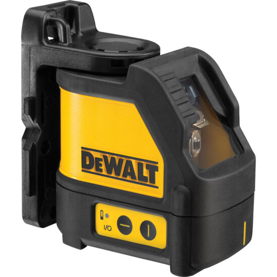

SAFETY INSTRUCTIONS FOR LASERS

Failure to follow all instructions listed below may result in electric shock, fire and/or serious personal injury.

SAVE THESE INSTRUCTIONS
- Do not operate the laser in explosive atmospheres, such as in the presence of flammable liquids, gases, or dust. Power tools create sparks which may ignite the dust or fumes.
- Use the laser only with the specifically designated batteries. Use of any other batteries may create a risk of fire.
- Store idle laser out of reach of children and other untrained persons. Lasers are dangerous in the hands of untrained users.
- Use only accessories that are recommended by the manufacturer for your model. Accessories that may be suitable for one laser, may create a risk of injury when used on another laser.
- Tool service must be performed only by qualified repair personnel. Service or maintenance performed by unqualified personnel may result in injury. .
- Do not use optical tools such as a telescope or transit to view the laser beam. Serious eye injury could result.
- Do not place the laser in a position which may cause anyone to intentionally or unintentionally stare into the laser beam. Serious eye injury could result.
- Turn the laser off when it is not in use. Leaving the laser on increases the risk of staring into the laser beam.
- Do not disassemble the laser tool. There are no user serviceable parts inside.
- Do not modify the laser in any way. Modifying the tool may result in Hazardous Laser Radiation Exposure.
- Do not operate the laser around children or allow children to operate the laser. Serious eye injury may result.
- Do not remove or deface warning labels. Removing labels increases the risk of exposure to radiation.
- Position the laser securely on a level surface. Damage to the laser or serious injury could result if the laser falls.
- lead from lead-based paints,
- crystalline silica from bricks and cement and other masonry products, and
- arsenic and chromium from chemically-treated lumber.
Your risk from these exposures varies, depending on how often you do this type of work. To reduce your exposure to these chemicals: work in a well ventilated area, and work with approved safety equipment, such as those dust masks that are specially designed to filter out microscopic particles.
Avoid prolonged contact with dust from power sanding, sawing, grinding, drilling, and other construction activities. Wear protective clothing and wash exposed areas with soap and water. Allowing dust to get into your mouth, eyes, or lay on the skin may promote absorption of harmful chemicals.
The label on your tool may include the following symbols.
V ………………… volts
mW ……………..milliwatts
………… laser warning
symbol
nm……………….wavelength in
nanometers
II(2)…………….. Class II (2) Laser
For your convenience and safety, the following label is on your laser.

Introduction
The DW088 lasers are self-leveling laser tools that can be used inside and outside for horizontal (level) vertical and plumb alignment projects.
GENERAL SAFETY RULES FOR BATTERY OPERATED TOOLS
Warning! Read and understand all instructions. Failure to follow all instructions listed below may result in electric shock, fire and/or serious personal injury.
Work area
- Keep your work area clean and well lit Cluttered benches and dark areas invite accidents.
- Do not operate power tools in explosive atmospheres, such as in the presence of flammable liquids, gases, or dust. Power tools create sparks which may ignite the dust or fumes.
- Keep bystanders, children, and visitors away while operating a power tool. Distractions can cause you to lose control.
Electrical safety
Use battery operated tool only with the specifically designed batteries. Use of any other batteries may create a risk of fire.
Battery
This tool is powered by three 1.5V AA size batteries.
Note: AR version does not include battery.
To install batteries:
- Lift up the battery compartment cover 1, as shown in Fig.A.
- Insert three fresh AA batteries in the compartment, placing the batteries according to (+) and (–) on the inside of the battery door.

Warning! Batteries can explode, or leak, and can cause injury or fire. To reduce this risk:
- Carefully follow all instructions and warnings on the battery label and package.
- Always insert batteries correctly with regard to polarity (+ and –), marked on the battery and the equipment.
- Do not short battery terminals.
- Do not charge batteries.
- Do not mix old and new batteries. Replace all of them at the same time with new batteries of the same brand and type.
- Remove dead batteries immediately and dispose of per local codes.
- Do not dispose of batteries in fire.
- Keep batteries out of reach of children.
- Remove batteries if the device will not be used for several months.
Personal safety
- Stay alert, watch what you are doing and use common sense when operating a laser tool. Do not use tool while tired or under the influence of drugs, alcohol, or medication. A moment of inattention while operating power tools may result in serious personal injury.
- Do not overreach. Keep proper footing and balance at all times. Proper footing and balance enables better control of the tool in unexpected situations.
- Use safety equipment. Always wear eye protection. Dust mask, non-skid safety shoes, hard hat, or hearing protection may be required for appropriate conditions.
Tool use and care
- Do not use tool if switch does not turn it on or off. Any tool that cannot be controlled with the switch is dangerous and must be repaired.
- Store idle tools out of reach of children and other untrained persons. Tools are dangerous in the hands of untrained users.
- Use only accessories that are recommended by the manufacturer for your model. Accessories that may be suitable for one tool, may become hazardous when used on another tool.
Service
- Tool service must be performed only by qualified repair personnel. Service or maintenance performed by unqualified personnel could result in a risk of injury.
- When servicing a tool, use only identical replacement parts. Follow instructions in the Maintenance section of this manual. Use of unauthorized parts or failure to follow Maintenance Instructions may create a risk of electric shock or injury.
To locate your nearest DeWALT service center call 1–800–4-DeWALT (1–800–433–9258) or go to http://www.DeWALT.com on the Internet.
OPERATING TIPS
- Use only new, high-quality, name brand batteries for best results.
- Ensure batteries are in good working condition. If the low battery red indicator light is flashing, the batteries need replacement.
- To extend battery life, turn laser off when not working with or marking the beam.
- To ensure the accuracy of your work, check to make sure your laser is calibrated often. See Field Calibration Check.
- Before attempting to use the laser, make sure it is positioned securely, on a smooth, flat surface.
- Always mark the center of the beam created by the laser.
- Extreme temperature changes may cause movement of internal parts that can affect accuracy. Check your accuracy often while working. See Field Calibration Check.
- If the laser has been dropped, check to make sure your laser is still calibrated. See Field Calibration Check.
LOW BATTERY INDICATION
The DW088 lasers are equipped with a red indicator light 2, as shown in Fig. B. The red indicator lights are located to the left of the on/off buttons (3, 4).

A flashing red indicator light indicates that the batteries are low and need to be replaced. The laser may continue to operate for a short time while the batteries continue to drain, but the beam(s) will quickly dim. After fresh batteries are installed and the laser is turned on again, the laser beam(s) will return to full brightness and the red indicator light will stay off. (A flashing laser beam is not caused by low batteries; see Out of Tilt Range Indicator.)
OPERATION
TO TURN THE LASERS ON AND OFF (FIg. B)
With the laser off, place it on a flat surface. This model has two ON/OFF buttons, one for a horizontal laser line 3 and one for a vertical laser line 4. Each laser line is powered on by pressing its ON/OFF button. The laser lines can be powered one at a time or at the same time. Pressing the ON/OFF buttons again turns the laser lines off.
USING THE LASERS
The beams are level or plumb as long as the calibration has been checked (see Field Calibration Check) and the laser beam is not flashing (see Out of Tilt Range Indicator).
Out of Tilt Range Indicator (Fig. C, D)
The lasers are designed to self-level. If the laser has been tilted so much that it cannot level itself (average > 4° tilt), it will flash the laser beam (Fig. D). The flashing beam indicates the tilt range has been exceeded and IS NOT LEVEL (OR PLUMB) AND SHOULD NOT BE USED FOR DETERMINING OR MARKING LEVEL (OR PLUMB). Try repositioning the laser on a more level surface.

Using the Lasers with Accessories
The lasers are equipped with a 1/4” x 20 female thread on the bottom of the unit. This thread is to accommodate current or future DeWALT accessories. Only use DeWALT accessories specified for use with this product. Follow the directions included with the accessory.
If you need any assistance in locating any accessory, please contact DeWALT Industrial Tool Co., 701 East Joppa Road, Towson, MD 21286 or call 1–800–4-DeWALT (1–800–433–9258). See our catalog on the World Wide Web at www.DeWALT.com.
Using the Pivot Bracket (Fig. E)
The lasers have a magnetic pivot bracket 5 permanently attached to the units. This bracket allows the unit to be mounted to any upright surface made of steel or iron. Common examples of suitable surfaces include steel framing studs, steel door frames and structural steel beams. The bracket also has a keyhole slot 6 allowing the unit to be hung from a nail or screw on any kind of surface. Position the laser and/or wall mount on a stable surface. Serious personal injury or damage to the laser may result if the laser falls.
Using the Laser with the Wall Mount (Fig. E)
The DW0860 Laser Wall Mount offers more mounting options for the DW088 lasers. The wall mount has a clamp 7 at one end which can be fixed to a wall angle for acoustic ceiling installation. At the other end of the wall mount is a screw hole 8, allowing the wall mount to be attached to any surface with a nail or screw.
Once the wall mount is secured, its steel plate provides a surface to which the magnetic pivot bracket can be attached. The position of the laser can then be fine-tuned by sliding the pivot bracket up or down on the wall mount.
Leveling the Lasers
s long as the lasers are properly calibrated, the lasers are selfleveling. Each laser is calibrated at the factory to find level as long as it is positioned on a flat surface within average ± 4° of level. No manual adjustments must be made.

MAINTENANCE
- To maintain the accuracy of your work, check the laser often to make sure it is properly calibrated. See Field Calibration Check.
- Calibration checks and other maintenance repairs may be performed by DeWALT service centers.
- When not in use, store the laser in the kit box provided. Do not store your laser at temperatures below -5 ºF (-20 ºC) or above 140 ºF (60 ºC).
- Do not store your laser in the kit box if the laser is wet. The laser should be dried first with a soft dry cloth.
CLEANING
Exterior plastic parts may be cleaned with a damp cloth. Although these parts are solvent resistant, NEVER use solvents. Use a soft, dry cloth to remove moisture from the tool before storage.
FIELD CALIBRATION CHECK
Checking Accuracy – Horizontal Beam, Scan Direction (Fig. F)
Checking the horizontal scan calibration of the laser requires two walls 30’ (9 m) apart. It is important to conduct a calibration check using a distance no shorter than the distance of the applications for which the tool will be used.
- Attach the laser to a wall using its pivot bracket. Make sure the laser is facing straight ahead.
- Turn on the laser’s horizontal beam and pivot the laser approximately 45º so that the right-most end of the laser line is striking the opposing wall at a distance of at least 30’ (9 m). Mark the center of the beamo (a).
- Pivot the laser approximately 90º to bring the left-most end of the laser line around to the mark made in Step 2. Mark the center of the beam (b).
- Measure the vertical distance between the marks.
- If the measurement is greater than the values shown below, the laser must be serviced at an authorized service center.
| Distance Between Walls | Allowable Distance Between Marks |
| 30’ (9 m) | 1/8” (3.0 mm) |
| 40’ (12 m) | 5/32” (4.0 mm) |
| 50’ (15 m) | 7/32” (5.0 mm) |

Checking Accuracy – Horizontal Beam, Pitch Direction (Fig. G)
Checking the horizontal pitch calibration of the laser requires a single wall at least 30’ (9 m) long. It is important to conduct a calibration check using a distance no shorter than the distance of the applications for which the tool will be used.
- Attach the laser to one end of a wall using its pivot bracket.
- Turn on the laser’s horizontal beam and pivot the laser toward the opposite end of the wall and approximately parallel to the adjacent wall.
- Mark the center of the beam at two locations (c, d), at least 30’ (9 m) apart.
- Reposition the laser to the opposite end of the wall.
- Turn on the laser’s horizontal beam and pivot the laser back toward the first end of the wall and approximately parallel to the adjacent wall.
- Adjust the height of the laser so that the center of the beam is aligned with the nearest mark (d).
- Mark the center of the beam (e) directly above or below the farthest mark (c).
- Measure the distance between these two marks (c, e).
- If the measurement is greater than the values shown below, the laser must be serviced at an authorized service center.
| Distance Between Walls | Allowable Distance Between Markss |
| 30’ (9 m) | 1/4” (6.0 mm) |
| 40’ (12 m) | 5/16” (8.0 mm) |
| 50’ (15 m) | 13/32” (10.0 mm) |

Checking Accuracy – Vertical Beam (Fig. H)
Checking the vertical (plumb) calibration of the laser can be most accurately done when there is a substantial amount of vertical height available, ideally 30’ (9 m), with one person on the floor positioning the laser and another person near a ceiling to mark the position of the beam. It is important to conduct a calibration check using a distance no shorter than the distance of the applications for which the tool will be used.
- Start by marking a 5’ (1.5 m) line on the floor.
- Turn on the laser’s vertical beam and position the unit at one end of the line, facing the line.
- Adjust the unit so its beam is aligned and centered on the line on the floor.
- Mark the position of the laser beam on the ceiling (f). Mark the center of the laser beam directly over the midpoint of the line on the floor.
- Reposition the laser at the other end of the line on the floor. Adjust the unit once again so its beam is aligned and centered on the line on the floor.
- Mark the position of the laser beam on the ceiling (g), directly beside the first mark (f).
- Measure the distance between these two marks.
- 8. If the measurement is greater than the values shown below, the laser must be serviced at an authorized service center.

| Ceiling Allowable Distance | Between Marks Height |
| 8’ (2.5 m) | 5/32 (3,5 mm) |
| 10’ (3.0 m) | 3/16 (4,5 mm) |
| 14’ (4.0 m) | 1/4 (6,0 mm) |
| 20’ (6.0 m) | 3/8 (9,0 mm) |
| 30’ (9.0 m) | 1/2 (13 mm) |
TROUBLESHOOTING
The Laser Does Not Turn On
- Make sure batteries are installed according to (+) and (–) on the inside of the battery door.
- Make sure the batteries are in proper working condition. If in doubt, try installing new batteries.
- Make sure that the battery contacts are clean and free of rust or corrosion. Be sure to keep the laser level dry and use only new, high-quality, name brand batteries to reduce the chance of battery leakage.
- If the laser unit is heated above 120 ºF (50 ºC), the unit will not turn on. If the laser has been stored in extremely hot temperatures, allow it to cool. The laser level will not be damaged by pressing the on/off button before cooling to its proper operating temperature.
The Laser Beams Flash (Fig. C, D)
The DW088 lasers have been designed to self-level up to an average of 4° in all directions when positioned as shown in Fig. C. If the laser is tilted so much that internal mechanism cannot level itself, it will flash the laser (Fig. D) – the tilt range has been exceeded. THE FLASHING BEAMS CREATED BY THE LASER ARE NOT LEVEL OR PLUMB AND SHOULD NOT BE USED FOR DETERMINING OR MARKING LEVEL OR PLUMB. Try repositioning the laser on a more level surface.
The Laser Beams Will Not Stop Moving
The DW088 lasers are precision instruments. Therefore, if the laser is not positioned on a stable (and motionless) surface, the laser will continue to try to find level. If the beam will not stop moving, try placing the laser on a more stable surface. Also, try to make sure that the surface is relatively flat, so that the laser is stable.
SERVICE AND REPAIRS
Note: Disassembling the laser level(s) will void all warranties on the product.
Important! To assure product SAFETY and RELIABILITY, repairs, maintenance and adjustment should be performed by authorized service centers. Service or maintenance performed by unqualified personnel may result in a risk of injury. To locate your nearest DeWALT service center call 1–800–4-DeWALT (1–800–433–9258) or go to http://www.DeWALT.com on the Internet.
PROTECTING THE ENVIRONMENT
Should you find one day that your DEWALT product needs replacement, or if it is of no further use to you, do not dispose of it with household waste. Please sort it out for separate recycling.

SPECIFICATIONS
| DW088 | DW088CG | |
| Light Source | Semiconductor laser diode | √ |
| Laser Wavelength | 630 – 680 nm Visible | 510 – 530 nm Visible |
| Laser Power | ≤1.3mW (each beam) CLASS II (2) LASER PRODUCT | √ |
| Working Range | 165’ (50 m) (with detector) | √ |
| Accuracy (Level) | ±1/8”per30’(±3mmper9m) | √ |
| Indicators | Flashing Indicator: battery low | √ |
| Flashing Laser: tilt range exceeded | √ | |
| Power Source | 3 AA (1.5V) size batteries (4.5V DC) | √ |
| Operating Temperature | 20°Fto115°F(-10 °Cto45°C) | √ |
| Storage Temperature | -5°Fto140°F(-20°Cto60°C) | √ |
| Environmental | Water Resistant | √ |
2 YEARS WARRANTY
DEWALT oers a 3-years warranty for these products from date of purchase, against functional faults cause by any material or labor fault during its manufacturing. This warranty includes.
product and/or components repairs or replacement, at no charge for the customer, including labor. The warranty is invalid under the following conditions:
- If the product was used under conditions other than normal.
- If the product was not used according to the instructions insert.
- If the product has been altered or repaired by unauthorized personnel.
DEWALT warranty covers repair or replacement of product and/or its components at no charge to the customer, including workmanship.
NOTE: Only in Mexico and Argentina, this warranty includes transportation charges originated within our service network. Only applicable for Mexico: Included the list of Authorized Service Centers where you can use the warranty and/or obtain parts, components, supplies and accessories. DEWALT is committed to deliver the product in a period not exceeding 30 working days from the date of receipt at our Authorized Service Center.
To make good on the warranty, the tool must not have been manipulated by personnel not authorized by DEWALT, and/or the invoice.
Importado por:
Black & Decker do Brasil Ltda.
Rod. BR 050, s/n° – Km 167
Dist. Industrial II
Uberaba – MG – Cep: 38064-750
CNPJ: 53.296.273/0001-91
Insc. Est.: 701.948.711.00-98
S.A.C.: 0800-703-4644
DeWALT Industrial Tool Co., 701 East Joppa Road, Towson, MD 21286
(Jul18) Part No. N622012 DW088, DW088CG
Copyright © 2018 DeWALT
The following are trademarks for one or more DeWALT power tools: the yellow and black color scheme, the “D” shaped air intake grill, the array of pyramids on the handgrip, the kit box configuration, and the array of lozenge-shaped humps on the surface of the tool.