Honeywell T104A Thermostatic Control Instruction Manual


INSTALLATION INSTRUCTIONS
APPLICATION
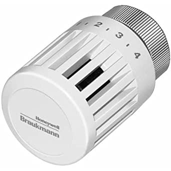
The T104A Thermostatic Control is used with a V110 Valve Body to control radiators, convectors, baseboard heating units, or other heating units with standard capacity requirements. The control is self-powered and requires no electrical connection. The T104A includes an integral sensor, setpoint dial and valve actuator. The T104A Control attaches to the valve body by threaded connections. The T104A must be mounted horizontally for accurate temperature regulation. It is not suitable for use inside enclosures or where the airflow around the sensor is restricted.
The setpoint dial has reference marks (1-6). The control has a low limit of 43°F (6°C) when the dial is turned fully clockwise to the frost protection mark*. The red button indicates the 68°F (20°C) setpoint limit. Higher settings may be made by holding in the button while turning. The thermostatic sensor is protected by a safety spring against temperatures to 125°F (52°C).
SPECIFICATIONS
- MATERIALS OF CONSTRUCTION:
- Body: Industrial grade plastics with low thermal conductivity.
Fastening Ring: Plated brass.
Internal Parts: Brass thermostat capsule, other metals. - TEMPERATURE RANGE: 43° to 79°F (6° to 26°C).
- MAX. SENSOR TEMPERATURE: 125°F (52°C).
MAXIMUM OAPPLICATION
The T104A Thermostatic Control is used with a V110 Valve Body to control radiators, convectors, baseboard heating units, or other heating units with standard capacity requirements. The control is self-powered and requires no electrical connection. The T104A includes an integral sensor, setpoint dial and valve actuator. The T104A Control attaches to the valve body by threaded connections. The T104A must be mounted horizontally for accurate temperature regulation. It is not suitable for use inside enclosures or where the airflow around the sensor is restricted.
The setpoint dial has reference marks (1-6). The control has a low limit of 43°F (6°C) when the dial is turned fully clockwise to the frost protection mark*. The red button indicates the 68°F (20°C) setpoint limit. Higher settings may be made by holding in the button while turning. The thermostatic sensor is protected by a safety spring against temperatures to 125°F (52°C).
SPECIFICATIONS
MATERIALS OF CONSTRUCTION:
- Body: Industrial grade plastics with low thermal conductivity.
- Fastening Ring: Plated brass.
- Internal Parts: Brass thermostat capsule, other metals.
- TEMPERATURE RANGE: 43° to 79°F (6° to 26°C).
- MAX. SENSOR TEMPERATURE: 125°F (52°C).
- MAXIMUM OVERALL DIMENSIONS: 2-1/8 in. (54 mm) wide, 3-5/16 in. (84 mm) long.
These are the setpoint temperatures, which correspond to the setpoint dial reference marks, under ideal conditions. Factor affecting the temperature at the sensor vary for each installation. It may be necessary to adjust the setpoint higher or lower to obtain the desired space temperature.

| Temperature | 0 | * | 1 | 2 | 3 | 4 | 5 | 6 |
| °F | Off | 43 | 46 | 54 | 61 | 68 | 73 | 79 |
| °C | Off | 6 | 8 | 12 | 16 | 20 | 23 | 26 |
AVAILABLE VALVE BODIES:

- T104B Control with remote sensor/setpoint.
- T104C Control with remote sensor and remote set-point.
- T104F Control with remote sensor.
- T104V Control with internal sensor and tamper-resistant setpoint and mounting.

INSTALLATION
IMPORTANT
Mount the T104A Control horizontally for accurate temperature regulation. The T104A built-in sensor may falsely sense heated air from the supply pipe if the control is not mounted horizontally. Use a T104F Control, which has a remote sensor, when space limita-tions do not permit horizontal mounting.
Do not install the T104A inside an enclosure. The buildup of heat inside an enclosure may cause false sensing, and therefore underheat-ing.
Mount the T104A horizontally. Make sure the bosses on the T100A base fit securely into the valve body grooves. Firmly hand tighten the knurled ring. Improper mounting can cause overheating. Refer to Fig. 4 for typical installations.

SETTINGS AND CALIBRATION
The T104A Control includes an adjustable range limiting pin (order additional pins separately). The pin is factory-set to limit the low range of the control to the frost protection (*) setting . The pin can be moved to a different low or high limit setting and lock point, or it can be removed. Use a second pin if both low and high limit settings are desired.
Setting the Limit
To set a limit different from the factory setting, proceed as follows:
- Determine the desired temperature range limit or locking temperature. Select the appropriate number on the adjustment knob to match the desired temperature setting.
- Lift the end cap off the adjustment knob. See Fig. 6.
- Remove the adjustment knob from the actuator as follows:
a. Turn the adjustment knob so the desired knob setting is aligned with the white line on the actuator base.
b. Pull the knob off the head or use a screw-driver inserted into one of the slots to pry off the knob. - Push up the limit pin and slide it into the slot that corresponds with the desired temperature limit. If the lower limit remains at the frost pro-tection mark (*), insert an additional pin in the slot that corresponds with the second limit.
• Example 1: If the desired temperature range is 43° to 73°F (6° to 23°C), leave the pin in the slot marked * and add one pin in slot 5.
• Example 2: If the desired temperature range is OFF to 68°F (23°C), move the pin to slot 5. No additional pin is required. - To replace the adjustment knob, realign the knob setting in step 3a with the white line on the base and push the knob toward the base. Make sure the three arm clips snap into place at the top of the adjustment knob. If the actuator was turned with the adjustment knob off, recalibrate the control according to the instructions in Recalibrate T100A Control section.
- Replace the end cap.


Locking the Control at a Single Temperature
- Determine the desired locking temperature. Select the appropriate number on the adjust-ment knob to match the desired temperature setting.
- Lift the end cap off the adjustment knob.
- Remove the adjustment knob from the actuator as follows:
a. Turn the adjustment knob so the desired knob setting is aligned with the white line on the actuator base.
b. Pull the knob off the head or use a screw-driver inserted into one of the slots to pry off the knob. - Insert the pin in slot 4a for 68°F (20°C) or slot 4b for 72°F (22°C).
- To replace the adjustment knob, align the knob setting from step 3a with the white line on the base and push the knob toward the base. Make sure the three arm clips snap in place at the top of the adjustment knob.
- Replace the end cap.

Recalibrate T104A Control
- Lift the end cap off the adjustment knob.
- Pull the knob off the head or use a screwdriver inserted into one of the slots to pry off the knob.
- Turn the actuator head clockwise until the head stops . The calibration indent should be aligned approximately with the white line on the base when the head stops. If the indent is 180 degrees from the white mark, unscrew the head completely from the base and rethread the head to the base so that it is aligned with the white mark. Turn the actuator head clockwise until the head stops. Complete removal of the head from the base is required only if the actuator was pre-viously dismantled.
- Turn the actuator head counterclockwise approximately one turn until the calibration indent on the head aligns with the white line on the base. For the 72°F (22°C) single tempera-ture setting, align the indent with the center of the adjustable limiting pin.
- Replace the adjustment knob by aligning the red button with the white line on the base and pushing the knob toward the base. For the 72°F (22°C) single temperature settin, align the red button with the center of the adjustable limiting pin. Make sure the three arm clips snap into place at the top of the adjustment knob.
- Replace the end cap.
TROUBLESHOOTING
| Symptom | Possible Cause | Solution |
| All sections of the radiator are not heating. | 1. Many radiators are over sized and all sections are not required to heat up to maintain the set room temperature. | 1. System is operating properly. |
|
Underheating. |
1. Sensor is in the wrong location. 2. T104A Control is mounted in a verti- cal position. 3. Flow through the valve is in the wrong direction. 4. Inadequate system temperature or pressure. 5. Steam traps are defective. 6. Air lock in the hot water system. 7. Scale or debris is blocking flow. 8. Heating cabinet dampers are closed. |
1. Change the sensor location or change the control type. See installa- tion instructions. 2. Mount the T104A horizontally. 3. Check the arrow on the valve body. It should be in the direction of the flow. Change the valve direction or flow direction. 4. Check the operating and limiting controls on the boiler. Check the cir- culating pump and isolating valves. 5. Repair or replace the traps. 6. Fully open the valve to allow air to pass. Install vents. 7. Flush the system. Do not use oil base additives. Clean strainer insert in steam applications. 8. Open or remove the dampers. |
|
Overheating. |
1. Sensor is in the wrong location. 2. Control is not properly installed. 3. Dirt or scale is under the seat, pre- venting tight shutoff. 4. Flow through the valve is in the wrong direction, damaging the valve seat. 5. Steam traps are defective. 6. Excessive differential pressure is forc- ing the valve open (hot water sys- tems). |
1. Change the sensor location or change the control type. 2. Set bosses in grooves and tighten knurled ring to the valve body. 3. Remove the control from the valve body, allowing the valve to open fully and flush away scale and debris. Reinstall the control and turn fully clockwise. If the valve does not fully close, remove the control and cartridge using a cartridge changer tool or service socket (isolate valve from system if not using changer tool). Inspect and clean valve seat area and disc. Always use a strainer insert in steam applications. 4. Check the arrow on the valve body. It should be in the direction of the flow. Change the valve direction or flow direction. Remove the valve cartridge and inspect for damage to the seat disk. 5. Repair or replace the traps. 6. Install a differential pressure regulator (D146A) to maintain less than 17 psi differential between supply and return pipes. |
| Chattering or knocking. |
1. Flow through the valve is in the wrong direction. 2. Vacuum in the system. 3. Excessive differential pressure. |
1. Check the arrow on the valve body. It should be in the direction of the flow. Change the valve direction or flow direction. 2. For steam—check traps and vents. For hot water—check expansion tank operation and location. 3. Install a differential pressure regulator (D146A) to maintain less than 17 psi differential between supply and return pipes. |
Resideo Technologies, Inc.
1985 Douglas Drive North, Golden Valley, MN 55422
© 2021 Resideo Technologies, Inc. All rights reserved.
The Honeywell Home trademark is used under license from Honeywell International, Inc. This product is manufactured by Resideo Technologies, Inc. and its affiliates.
1-800-468-1502
62-3046—01 M.S. Rev. 06-21 | Printed in United States