Honeywell TB7200 Wireless Communication Card for Communicating Thermostats Instruction Manual


Honeywell TB7200 Wireless Communication Card for Communicating Thermostats

INSTALLATION INSTRUCTIONS
APPLICATION
The Honeywell wireless communication card (TB-VWG-APP-1014) and related WirelessStatNetwork.jar driver file are designed for use with WEBs-AX controllers to integrate Honeywell TB7200 and TB7600 Series wireless thermostats into a WEBs-AX building control system. This card allows the integrator to work in the familiar Workbench tool set using any of the TB7200 and TB7600 Series wireless thermostats. The wireless communication card and TB7200 and TB7600 Series thermostats use ZigBee® wireless mesh. The wireless thermostats are ideal for retrofit applications where the addition of communicating field bus wiring in the building space is difficult or cost-prohibitive. This document covers the mounting of the wireless communication card in a WEBs-AX controller.
BEFORE YOU BEGIN
Included in the wireless card package you should find the following items:
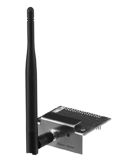
- The wireless communication card
- A local antenna
phillips screwdriver is required for installation.
To add the Honeywell wireless thermostat network to a WEBs system, you need two .jar files for the WEBStation-AX. You can download these files from the Honeywell Buildings Forum at buildingsforum.honeywell.com.
Jar Files Needed:
- Wireless Thermostat Network Driver: WirelessTstat.jar, version 4.0.4.8 or greater.
- Wireless Thermostat Device and Point Configuration: Wireless TstatDevices.jar, version 4.0.4.8 or greater.
INSTALLATION
CAUTION
Erratic System Operation Hazard. Failure to follow proper wiring practices can introduce disruptive electrical interference (noise). Keep wiring at least one foot away from large inductive loads such as motors line starters, lighting ballasts, and large power distribution panels. Shielded cable is required in installations where these guidelines cannot be met. Ground shield only to grounded controller case.
IMPORTANT: All wiring must comply with local electrical codes and ordinances or as specified on installation wiring diagrams.
- Power to the WEBs-AX controller must be OFF when installing or removing the wireless communication card or damage will occur! Also, be careful to plug the wireless communication card into its connector properly (pins aligned).
- Only one wireless communication card can be installed in a WEBs-AX controller. Always install the card in option slot 1 in WEB-2xx and WEB-6xx models. Option slot 1 or 2 can be used on WEB-7xx models.
Mounting the wireless communication card on a WEBs-AX controller
- Remove power from the controller.
- Remove the controller cover. To do this, press in the four tabs on both ends of the unit, and lift the cover off. NOTE: If other expansion accessory modules are plugged into the controller, you may need to slide them away from the unit to get to the cover tabs.
- Remove the battery and bracket assembly by taking out the four screws. (Fig. 1)
- Unplug the battery from the connector on the controller.
- Remove screws and battery assembly.
- Remove the front blanking end plate for option slot 1 (Com1) on WEB-2xx and WEB-6xx controllers and option slot 1 or 2 (Com3 or Com4 in the WEBStation-AX) on WEB-7xx controllers.
- Carefully insert the pins of the wireless communication card into the appropriate socket. The mounting holes on the option board should line up with the standoffs on the base board. If they do not, the connector is not properly aligned. Press until the option card is completely seated.
- Plug the battery cable back into the battery connector on the controller
- Set the battery and bracket assembly back over the option card slots, with the mounting holes aligned with the standoffs.
- Re-fasten screws through battery bracket the four hold-ing screws through. DO NOT over tighten.
- Replace the controller cover.
- Install the antenna. (Fig. 2)


STATUS LED INDICATORS
See the table below for status indicators on the wireless communication card.

Table 1. Status LED Indicators
SPECIFICATIONS
- Thermostat Compatibility: TB7200 and TB7600 Series wireless thermostats
- Network Protocol: ZigBee wireless mesh
- WEBs-AX Controllers: Compatible with WEB-2xx, WEB-6xx, and WEB-7xx
- Platform: WEB-2xx and WEB-6xx – WEBStation-AX 3.0 or later WEB-7xx – WEBStation-AX 3.5 or later
- Number of Thermostats Supported: WEB-2xx – up to 30 wireless thermostats WEB-6xx & WEB-7xx – up to 50 wireless thermostats
- Connections: 2 x 15 gold plated header for serial connection to compatible WEBs-AX controller and SMA connector for antenna.
- Input: Reset button
- Status LED: 1 green LED
- Board Dimensions: 2.2 in. x 1.75 in. (excluding antenna)
- Approximate Shipping Weight: .02 lb
- Agency Approvals: Compliant with FFC Part 15, Subpart C; C-Tick: EN55022:2006, IEC 61326-1:2005
DISCLAIMER
NO WARRANTY. Honeywell, Inc. (herein after referred to as “Honeywell”) makes no warranty as to the accuracy of or use of this technical documentation. Any use of the technical documentation or the information contained therein is solely at the risk of the user.
Documentation may include technical or other inaccuracies or typographical errors. Honeywell reserves the right to make changes to this document without prior notice, and the reader should in all cases consult Honeywell to determine whether any such changes have been made. The information in this publication does not represent a commitment on the part of Honeywell.
Honeywell shall not be liable for incidental or consequential damages resulting from the furnishing, performance, or use of this material.
Electronic controls are static sensitive devices. Discharge yourself properly before manipulation and installing the Honeywell wireless gateway.
Honeywell, Inc. may not be held liable for continued reliable, or robust operation of any and all wireless based devices. Although Honeywell has taken many precautions in assuring the robustness of the TB7200/7600 Series wireless thermostat product line and associated network access point. Please note; future application of additional wireless devices utilizing the same or similar channels and / or frequencies may degrade performance of overall system and / or reliability.
Non-approved modifications or changes made to the wireless communication card or wireless thermostats may void the FCC compliance of the and wireless thermostats.
This device complies with Part 15 of the FCC rules. Operation is subject to the following two conditions: (1) This device may not cause harmful interference, and (2) This device must accept any interference received, including interference that may cause undesired operation.
NOTE: The manufacturer is not responsible for any radio or tv interference caused by unauthorized modifications to this equipment. Such modifications could void the user’s authority to operate the equipment.