Honeywell ENC-H-001 Backplate Panel Installation Guide


Honeywell ENC-H-001 Backplate Panel 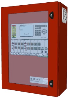

INSTALLATION INSTRUCTIONS
ENC-H-001
Small-sized enclosure (12 in. x 18 in. x 4 in.) with integral DIN-rail, 24Vac, 40VA transformer, AC convenience outlet, removable door. Accommodates a WEB-201/600 controller and one IO-34-H, or a WEB-201/600, IO-16-H, and NPB-PWR-H.
ENC-H-002
Large-sized enclosure (12 in. x 28 in. x 4 in.) with integral DIN-rail, 24Vac, 40VA transformer, AC convenience outlet, removable door. Accommodates a WEB-201/600 controller and up to four IO-16-H and an NPB-PWR-H, or other possible combinations.
ENC-H-BPK-1
Perforated backplate panel (8 in. x 11 in.).
ENC-H-BPK-2
Perforated backplate panel (11 in. x 11 in.).

An optional backplate panel may be installed if ENC-H-002 is to house user-supplied ancillary items such as relays or other devices.This document covers the mounting and wiring of WEBs™ ENC series enclosures for housing the WEB-201 or WEB-600 series controller and its expansion modules. It assumes you are an engineer, technician, or service person who is performing system design or installation. Instructions apply to the following models:
NOTE: Separate documents cover the mounting and wiring of WEB-201 and WEB-600 series controllers (including the NPB-PWR-H and NPB-PWR-UN-H power supply modules), as well as documents for WEB- 201/600 I/O expansion modules. See Related Documentation, page 2. All certifications and listing information related to a WEB-201/600 controller can be found in its mounting and wiring document.
PRODUCT OVERVIEW
The ENC series includes two different enclosures used to house WEB-201 or WEB-600 systems:
ENC-H-001
The small enclosure is 18-gauge steel, at 12 in. wide x 18 in. tall x 4 in. in. deep enclosure with a single DIN rail. DIN rail is mounted vertically. The small enclosure will hold one WEB-201/ 600 and one IO-34-H module.
ENC-H-002
The large enclosure is 16-gauge steel, 12 in. wide x 28 in. tall x 4 in. deep enclosure with a single DIN rail, also mounted vertically. The large enclosure will hold one WEB-201/600, an NPB-PWR-UNH, and up to four IO-16-H modules. If space permits, an optional perforated backplate: ENC-H-BPK-1 (8 in. x 11 in.) or ENC-H-BPK-2 (11 in. x 11 in.) may be installed if the enclosure is to house user-supplied ancillary equipment such as relays or other control devices. For more details, see Install perforated backplate panel.
Common Enclosure Features
Both enclosures (ENC-H-001 and ENC-H-002) provide the following features.
- Construction of 18- or 16-gauge steel, hinged door with lift-off hinges, 1/2-in. and 3/4-in. conduit knockouts, thumbscrew door latch, with hasp to place a user-supplied padlock if desired.
- Wiring compartment with 5A switch/circuit breaker and single 115V AC receptacle (NEMA 5-15R) for test equipment, and a 40 VA, 24V transformer. The switch/breaker is for WEBs equipment only. The AC receptacle is not controlled or protected by switch/breaker in the unit, and is rated for 5A maximum load.
- Units are designed for 120Vac service only.
- Provided 40 VA transformer may be used to power a user-provided IO-34-H or NPB-PWR-H power supply.
- The transformer is not used for applications where a user-supplied NPB-PWR-UN-H supply is provided.
- WEB-201/600, IO-16-H, IO-34-H. NPB-PWR-H, and NPB-PWR-UN-H lock on the DIN rail with #6-32 screws (provided). DIN rail clips are not necessary.
- Units are designed to accept Panduit G1X1.5LG6-1 wiring duct for cable management (Panduit with external cross-section dimensions of 1.25 in. wide x 1.63 in. high, with cover C1.5LG6 in place).
Related Documentation
For more information on mounting and wiring a WEB-201/600 and expansion modules, refer to these documents:
- WEB-201/600 Installation Instructions (includes NPB-PWR-H, NPB-PWR-UN-H mounting/wiring details) form number 95-7722
- IO-16-H Installation Instructions, form number 95-7723
- IO-34-H Installation Instructions, form number 95-7724.
PREPARATION
Unpack the ENC-H-001 or -002 unit and inspect the contents of the package for damaged or missing components. If damaged, notify the appropriate carrier at once and return any damaged components for immediate repair or replacement. See the “Returning a Defective Unit” section in the WEB-201/ 600 mounting and wiring guide.
Included in this Package
Included in this package you should find the following items for an ENC-H-001 or ENC-H-002, or for backplates
ENC-H-BPK-1 or ENC-H-BPK-2.
ENC-H-001 or ENC-H-002
- an ENC-H-001 or -002 metal enclosure with removable hinged door, and permanently mounted DIN rail, containing these pre-installed items:
- a 40VA, 24V secondary / 120V primary transformer, pre-wired to a switch/circuit breaker and a terminal block for AC line input. A two-wire pigtail cable is con-nected to the transformer secondary.
- AC convenience outlet (5A maximum rating) on wiring compartment cover.
- a hardware bag, containing #6-32 x 1/4 in. screws, #6-32 keps nuts, one wire mounting clamp (for AC wire), a section of split loom tubing, and tie wraps.
- this document, ENC-H-001 or -002 Enclosure Install Guide, Form Number 62-0299
ENC-H-BPK-1 or ENC-H-BPK-2
- a perforated backplate panel.
- four #6-32, 3/8 in. hex male-to-female standoffs.
- four #6-32 keps nuts.
- this document, ENC-H-001 or -002 Enclosure Install Guide, Form Number 62-0299
Material and Tools Required
The following supplies and tools are required for installation:
- Suitable tools and supplies for mounting enclosure, WEB-201/600 and expansion modules, and for making all wiring terminations. A ¼ in. nut driver can be used to fasten all screws and keps nuts included with the unit.
- If using Panduit inside the enclosure, a suitable length of Panduit part number G1X1.5LG6 and Panduit cover part number C1.5LG6.
PRECAUTIONS
This document uses the following warning and caution conventions:
CAUTION: Cautions remind the reader to be careful. They alert readers to situations where there is a chance that the reader might perform an action that cannot be undone, might receive unexpected results, or might lose data. Cautions contain an explanation of why the action is potentially problematic.
WARNING: Warnings alert the reader to proceed with extreme care. They alert readers to situations where there is a chance that the reader might do something that can result in personal injury or equipment damage. Warnings contain an explanation of why the action is potentially dangerous.
Safety Precautions
The following items are warnings relating to the power supply wiring to an ENC-H-001 or -002 enclosure. Be sure to heed these warnings to prevent personal injury or equipment damage.
WARNING:
- The circuit powering the ENC-H-001 or -002 is 115Vac at 60 Hz. Disconnect power before installation or servicing to prevent electrical shock or equipment damage.
- The 115Vac convenience outlet on the enclosure’s power wiring shield is rated for a 5A maximum load. Do not exceed this rating with any equipment powered from this outlet.
- Make all connections in accordance with national and local electrical codes. Use copper conductors only.
- To reduce the risk of fire or electrical shock, install in a controlled environment relatively free of contaminants.
- This system is only intended for use as a monitoring and control device. To prevent data loss or equipment damage, do not use it for any other purpose.
INSTALLATION SUMMARY
Installation of an ENC-H-001 or -002 enclosure is covered in the following main sections:
- Pre-Installation, page 3
- Mounting and Dimensions, page 5
- Power Wiring, page 7
- Mounting Devices on the DIN Rail, page 9
- Grounding Devices and Connecting Power, page 10
After completing these tasks, please refer to the appropriate Installation Guide for the devices you are installing in the enclosure.
PRE-INSTALLATION
The following pre-installation tasks may be helpful:
- Removing and replacing the enclosure door, page 3
- Locate and mark mounting holes, page 3
- Locate and remove enclosure knockouts, page 4
NOTES: If using Panduit inside the enclosure, wait until after mounting the enclosure to the wall before mounting the Panduit track onto the enclosure studs (4 in. on center) on either side of the enclosure. Otherwise, the Panduit will interfere with access to the 4 main mounting holes. Also wait until after mounting the enclosure before installing an optional ENC-H-BPK-1 or ENC-H-BPK-2 backplate at the enclosure’s bottom. For more details, see the “Install perforated back-plate panel (optional, ENC-H-002 only)” section on page 6.
Removing and replacing the enclosure door
The door on an ENC-H-001 or -002 enclosure is removable. It is often convenient to remove the enclosure door before other mounting and wiring. This also provides a lighter unit for initial mounting to the wall.
NOTE: A short, green, grounding wire is pre-attached inside the enclosure, near the bottom left side. One end is shipped fastened to the back wall (to speed door removal). After replacing the door, move that wire end to the door—remove the #6-32 keps nut, move the wire end to the screw post inside the door, and refasten.
REMOVING THE DOOR OF A ENC-H-001 OR -002 ENCLOSURE.
- Open the door about halfway.
- If the green grounding wire near the bottom is fastened to the screw post on the inside of the door, remove the #6-32 keps nut from the post and set aside. Pull the grounding wire free from the door.
- Slide the door toward the top of the unit, until the hinge tabs on the door clear the hinge pins on the enclosure.
- Lift the door away from the enclosure.
REPLACING THE DOOR OF A ENC-H-001 OR -002 ENCLOSURE.
- Align the hinge tabs on the door above the hinge pins on the left wall of the metal casing.
- Slide the door toward the bottom of the unit, until the door hinge tabs fully seat onto the hinge pins.
- Near the bottom of the enclosure, slide the green grounding wire onto the door’s screw post and fasten with a #6-32 keps nut. See Fig. 2 or Fig. 3.
- Close the door and latch, if necessary.
Locate and mark mounting holes
The ENC-H-001 or -002 enclosure has four main mounting holes on its back wall—the upper two holes are keyhole types. It is often convenient to mark the location of the mounting holes in the wall before beginning another enclosure assembly.
LOCATE AND MARK ENCLOSURE MOUNTING HOLES.
- With the enclosure door opened or removed, position the enclosure on the wall where it will be installed.
NOTE: See Fig. 2 (ENC-H-001) or Fig. 3 (ENC-H-002) for locations and dimensions of enclosure mounting holes. - Carefully mark the mounting hole locations, and remove the enclosure.
- Drill the needed pilot holes in the wall. For example, drill 5/16 in. holes for wall anchors if anchors are used.
Locate and remove enclosure knockouts
The ENC-H-001 or -002 enclosure has numerous knockouts on the top, sides, and bottom (see Fig. 1). Locate and remove any knockouts required for conduit and cabling entering the unit before mounting it to the wall. Also install the appropriate conduit or cable clamps to the removed knockouts.
LOCATE AND MARK ENCLOSURE MOUNTING HOLES.
- Depending on which direction the conduit and cabling will be brought to the enclosure, remove the appropriate knockouts. Note that four (4) knockouts are available going into the shielded wiring area.
- Install the appropriate conduit or cable clamps in the knockout holes.
Fig. 1 provides the locations of knockouts in both the ENC-H-001 and ENC-H-002 enclosure models. Two knockout sizes are used: 0.95 in. for 1/2 in. conduit, and 1.20 in. for 3/4 in. conduit.

MOUNTING AND DIMENSIONS
NOTE: Mount the ENC-H-001 or -002 enclosure in an indoor location only. For further environmental requirements, see the “Mounting” section in the WEB-201/ 600 Installation Instructions document.
Following “Pre-installation” tasks, the enclosure is ready for wall mounting. Install fasteners in all 4 mounting holes, tightening securely. For example, if wall anchors were ENC-H-001 AND ENC-H-002 ENCLOSURE INSTALL GUIDE installed in 5/16 in. holes, use four #14 anchor bolts, or other appropriate fasteners, as needed to securely fasten. After mounting, replace the enclosure door if still removed, see “Removing and replacing the enclosure door”.
- See Fig. 2 for ENC-H-001 enclosure wall mounting dimensions.
- See Fig. 3 for ENC-H-002 enclosure wall mounting dimensions.

ENC-H-001 AND ENC-H-002 ENCLOSURE INSTALL GUIDE

Install perforated backplate panel (optional,ENC-H-002 only)
If sufficient room is available in the bottom of an ENC-H-002 (apart from what is used by the controller and any attached modules), you can install one of the two available backplate panels. Auxiliary gear such as relays or transducers can then be mounted to the backplate using #8 x 3/8 in. self-taping sheet metal screws (not provided).
The two backplate panel options are:
- ENC-H-BPK-1 (8 in. x 11 in.): Space available if installing a maximum of WEB-201/600, an IO-34-H, and one IO-16-H module in the ENC-H-002 (requires minimum bottom clearance of 8.5 in.).
- ENC-H-BPK-2 (11 in. x 11 in.): Space available if installing a maximum of WEB-201/600 and an IO-34-H module in the ENC-H-002 (requires minimum bottom clearance of 11.5 in.).
INSTALL OPTIONAL ENC-H-BPK PERFORATED BACKPLATE PANEL.
- At the bottom back of the ENC-H-002 enclosure, fasten the four male-to-female hex standoffs on the appropriate enclosure studs, as shown in Fig. 4.
- Position the ENC-H-BPK-1 or ENC-H-BPK-2 backplate onto the threaded studs of the standoffs, and fasten securely with the four provided #6-32 cups nuts. Following all other enclosure installation and mounting of the controller and expansion modules, install auxiliary gear as needed onto the backplate.

POWER WIRING
The ENC-H-001 or -002 enclosure comes pre-wired with a 24Vac, 40VA transformer with a combination circuit breaker/switch on the transformer primary side, to allow shutting down of connected 24V equipment for service. In addition, an un-switched 115V convenience outlet is provided. The secondary (24V) side of the transformer is pre-wired with a pigtailed two-lead harness for connection to the 24V module powering the WEB-201/600.
WARNING: Input voltage is 115Vac only. Disconnect power to this circuit before installation to prevent electrical shock or equipment damage.
CAUTION: The 115V convenience outlet is rated for a 5A maximum load. Do not exceed this rating with any devices (service equipment, etc.) powered from this outlet.
The following sections provide more details:
- Removing the Wiring Shield, page 7
- Earth Grounding, page 8
- Connecting the 120Vac Power Circuit, page 8
- Re-routing wiring for 120V module (NPB-PWR-UN-H), page 8
Removing the Wiring Shield
The wiring shield is fastened by mounting tabs and three keps nuts. The nuts are screwed on enclosure studs, two that extend down from the top, and one from the back below the wiring shield area (See Fig. 5). Use a 1/4 in. nut driver to remove the three keps nuts, and set them aside.

Fig. 5. Power wiring shield for ENC-H-001 or -002 enclosure
Carefully move the shield out and away from the power wiring area. Being careful not to strain any wires.
NOTE: To replace the wire shield when finished, first carefully stuff all contained wiring back in the wiring area, then replace the shield assembly and refasten the three keps nuts previously removed.
Earth Grounding
Inside the wiring area, locate the grounding stud (Fig. 6). Connect to a nearby earth ground, using 14 AWG or larger wire

Also, ensure that the cover of the enclosure has its grounding wire connected. See “Removing and replacing the enclosure door” on page 3. (Check the Note.) Later, after mounting the WEB-201/600 controller and any DIN-mounted modules, you must connect the earth ground wire of each device to other enclosure studs (located outside of the shielded area). See “Grounding Devices and Connecting Power” on page 10.
Connecting the 120Vac Power Circuit
After “Removing the wiring shield” and making the “earth grounding” termination, connect the 120V line and neutral wires to the two-position screw terminal block. See Fig. 7.

Fig. 7. ENC-H-001 or -002 enclosure power supply connections.
This is the extent of connections required under the shield if using either of the 24V powered modules (IO-34-H, NPB-PWR-H). If using either of these modules, replace the shield assembly and refasten using the three keps nuts (see Removing the Wiring Shield, page 7).
CAUTION: The supplied transformer is for powering the WEB-201/600 and directly attached modules only. Any other 24Vac-powered equipment should be powered from a different source. If using an NPB-PWR-UN-H (120V powered) module instead of a 24V powered module, you need to make some additional wiring changes. See the next section “Re-routing wiring for 120V module (NPB-PWR-UN-H).”
Re-routing wiring for 120V module (NPB-PWR-UN-H)
In addition to “Removing the Wiring Shield,” making the “Earth Grounding” termination, and “Connecting the 120Vac Power Circuit,” you must re-route the wiring to the transformer primary side to change it to the NPB-PWR-UNH input circuit, including the circuit breaker/switch. Do this by removing and replacing two wire nuts, and re-routing wire as shown in Fig. 8 and described in procedure 6: RE-routing wiring for 120Vac module., page 9.
CAUTION: The supplied transformer becomes disconnected in this case. Leave the transformer mounted in place, to block access to the 120Vac connections in the power wiring area under the metal shield.

Fig. 8. Schematics of 24Vac wiring (as shipped) and re-routed 120Vac wiring (optional).
RE-ROUTING WIRING FOR 120VAC MODULE.
- With the wire shield positioned out of the way, carefully cut the tie wrap that bundles the transformer’s primary wires (black and white) to the two 18 AWG black and white lead wires.
- Remove the two wire nuts connecting the black and white wires, and disconnect the wires so that the 18 AWG black and white lead wires are free.
Replace the wire nuts with the black and white primary leads of the transformer (capping each wire). - Route both freed AC lead wires through a piece of split loom tubing and secure with a cable clamp, fastened to the enclosure stud immediately below the shielded wiring area. See Fig. 8 above.
- Replace the shield cover as previously noted in Removing the Wiring Shield, page 7. The AC lead wires are now available to power an NPB-PWR-UNH and are connected to the switch in the face of the shield assembly.
MOUNTING DEVICES ON THE DIN RAIL
NOTE: Before mounting a WEB-201/600 controller in the enclosure, install any communications option cards first. Refer to the mounting and wiring sheet included with any option card. For general DIN mounting details, see the mounting and wiring guide for the controller and its modules.
In the ENC-H-001 or -002 enclosure, the WEB-201/600 controller and all attached modules mount on the vertical DIN rail. Each device fastens in place using two #6-32 x ¼ in. screws through the mounting tabs of its base, secured into specially-aligned holes in the back of the enclosure (note DIN rail end-clips are not needed or used). As shown in Fig. 9 below, the controller is always mounted first, at the bottom of the module assembly.

Fig. 9. The WEB-201/600 is always bottom device on DIN rail, and first to be secured with screws.
Also, note the following:
- The power module (IO-34-H, NPB-PWR-H, or NPB-PWR-UN-H) is always the top device on the DIN rail.
- IO-16-H modules, if any, mount in-between the WEB-201/ 600 and the top-most power module.
- Place all (or nearly all) of the devices onto the DIN rail to start, and slide them around as needed. Start fastening devices with the screws starting at the bottom device. The WEB-201/600 is the first device you secure with two screws (Fig. 9.). Next, mate the next module with the controller, secure it with two screws, and continue to the next module. The last module secured with the #6-32 x 1/4 in. screws is top power module (IO-34-H, NPB-PWR-H, or NPB-PWR-UN-H).
GROUNDING DEVICES AND CONNECTING POWER
NOTE: Complete details on terminating earth ground and supply power are found in the mounting and wiring guides for each controller and expansion module. This section provides an overview, along with notes that apply to mounting in an ENC-H-001 or -002 enclosure. See the following subsections: Grounding wires, page 10, Module power, page 11, Final Wiring and Startup, page 11.
Grounding wires
The WEB-201/600 controller and any DIN-mount module are each shipped with a grounding wire that has a quick-disconnect 0.187” female connector.
To ensure maximum electrical protection, for each device:
- Connect its earth grounding wire to the device’s grounding spade lug connector.
- Secure the wire’s ringed end to a nearby enclosure stud, using the #6-32 nuts provided.
This provides a suitable ground path via the main earth ground connection to the enclosure. See Earth Grounding, page 8, for related details.

Fig. 10. Example grounding wires and power connections to different module combinations.
Module power
In the ENC-H-001 or -002 enclosure, the top-most module supplies power to the attached WEB-201/600 controller plus any other chained IO-16-H modules. This module is one of the following:
- IO-34-H or NPB-PWR-H: Requires connection to both 24Vac lead wires coming from the transformer secondary (lead wires are pre-connected to the screw terminals on the transformer).
- NPB-PWR-UN-H: Requires connection to the two re-routed 120Vac lead wires coming from the bottom of the shield assembly. See Re-routing wiring for 120V module (NPB-PWR-UN-H), page 8.
See Fig. 10 for examples. Do not connect AC power to the enclosure circuit until other wiring is completed.
Final Wiring and Startup
After completing termination of Grounding wires and Module power connections, wire all I/O points according to mounting and wiring instructions for each device. Connect any Ethernet and/or other communications cables needed, as described in the WEB-201/600 Installation Instructions.
NOTE: See Related Documentation, page 2. To power up the enclosure, follow Procedure 7 below.
ENCLOSURE POWER STARTUP.
- At the enclosure, switch the circuit breaker/switch to the OFF position.
- Energize the 120Vac circuit wired to the enclosure.
- At the enclosure, switch the circuit breaker/switch to the ON position to power all connected devices, and moni-tor the LEDs on devices to verify proper startup.
REPLACEMENT PARTS
Standard replacement parts are listed in Table 1 below.
| Part Number | Description |
| AT72D1683 | 24Vac 40VA Replacement Transformer may be ordered from a local Honeywell supplier. |
ENC-H-001 AND ENC-H-002 ENCLOSURE INSTALL GUIDE
UL LISTING
Honeywell has obtained a UL Listing on ENC-H-001 and ENC-H-002 enclosures from Underwriters Laboratories Inc. UL investigation of these enclosures does not include investigation of any equipment or material contained therein. Honeywell has obtained separate UL Listings for WEBs products that it ships installed within these enclosures. Please note any user-supplied equipment or material is not covered by this UL Listing.
By using this Honeywell literature, you agree that Honeywell will have no liability for any damages arising out of your use or modification to, the literature. You will defend and indemnify Honeywell, its affiliates and subsidiaries, from and against any liability, cost, or damages, including attorneys’ fees, arising out of, or resulting from, any modification to the literature by you.