Huawei M8544-EL-Z37 Wireless CCTV Camera User Guide


HUAWEI M8544-EL-Z37 Wireless CCTV Camera

Packing List and Qualification Card
Component
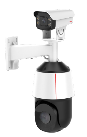
- M6721-E-Z31 PTZ dome camera 1
- M6741-E-Z37 PTZ dome camera 1
- Mount 1
- M2141-EVL (2.8-12 mm) bullet camera 1
- Quick Start Guide 1
- Universal joint 1
Additional Guides Available
To obtain the latest documents, including the Product Documentation and FOSS License Information, visit http://support.huawei.com/enterprise and enter the camera model to search for related documents.
You can also log in to http://support.huawei.com/enterprise or scan the QR code using a mobile phone to download the Technical Support APP. Then start this app and choose Products> Intelligent Vision to obtain the latest documents.
Introduction to Cable Ports
Cable ports of a PTZ Dome Camera

NO-Item-Description
- POWER: Power input port. 24 V AC (-25% to +24.9%).
- LAN: 0M/100M adaptive network port. The IP addresses of the two network ports are the same. One port is used to connect to the switch, and the other is used to connect the bullet camera.
- GND: Ground port of a camera.
- RS485: RS-485 port. This port provides a transparent data channel used for half-duplex transmission between the camera and the connected device.
- AUDIO IN\AUDIO OUT: Audio-in/Audio-out port and audio ground port.
ALARM_OUT: Alarm output port. The value n can be 0 and 1. Each ALARM_OUT and ALARM_REFn form a group of alarm output. A maximum of two groups are supported. The rated voltage of an alarm-out device is less than or equal to 30 V DC or 125 v ac, and the rated current is less than or equal to 200 mA. - ALARM_GND: Alarm-in ground port.
ALARM_INn: Alarm-in port. The value n can be 0, 1, 2, and 3. Each ALARM_IN and ALARM-GND form a channel of alarm input. A maximum of four channels of alarm input are supported.
DescriptionCable ports of a bullet camera

NO-Item-Description
- PoE/LAN: 10M/100M network port. This port supports PoE.
- POWER: Power input port. 12 V DC (±25%).
- RS485: RS-485 port. This port provides a transparent data channel for half-duplex transmission between the camera and the connected device.
- ALARM_OUT: Alarm output port. The value n can be 0 and 1. Each ALARM_OUT and ALARM_REFn form a group of alarm output. A maximum of two groups are supported. The rated voltage of an alarm-out device is less than or equal to 30 V DC or 125 v ac, and the rated current is less than or equal to 200 mA.
ALARM_REF: Alarm output port. The value n can be 0 and 1. Each ALARM_OUT and ALARM_REFn form a group of alarm output. A maximum of two groups are supported. The rated voltage of an alarm-out device is less than or equal to 30 V DC or 125 v ac, and the rated current is less than or equal to 200 mA.
ALARM_IN: Alarm input port. There may be multiple alarm input ports. For a given number of ports, n, they are numbered (for example, ALARM_IN0, ALARM_IN1, …, ALARM_INn). Each one connects to the GND connection to form a single alarm input.
ALARM_GND: Alarm input ground port. - AUDIO_IN/ AUDIO_OUT: Audio-in/Audio-out port and audio ground port.

Use the Phillips screwdriver to remove the camera bottom cover. Then, you can see the Reset button, SD card slot and system running status indicator.
Device Installation
A. SD Card Installation
Use a 2# Phillips screwdriver to remove the bottom cover, and insert the SD card.

CAUTION
Do not disassemble the PTZ dome camera yourself or remove the lens protective film before the installation is complete. Ensure that the weight-bearing capacity of the pole, ceiling, wall, and brackets exceeds 30 kg and the installation environment is secure and reliable. Also, avoid magnetic interference nearby.
B. Pole-Mounted Installation
- Install the universal joint:
Use three M6 screws to secure the universal joint to the smart tracking mount, and then tighten the screws. - Secure the smart tracking mount to the pole mount:
Align the screw holes on the smart tracking mount with those on the pole mount, and tighten the M8 screws. The tightening torque is 8 N.m. - Secure the mount to the pole:
- Thread cables through the smart tracking mount
- Loosen the three hose clamps and route them through the mounting holes on the pole mount. Then, route
the cables that need to be connected to the pigtails of the PTZ dome camera through the pole mount. - Place the hose clamps around the pole and fasten the hose clamps to fix the pole mount to the pole.
- Install the camera:
- Thread the network cable through the PG waterproof connector and tighten the PG waterproof connector.
- Install the bullet camera on the universal joint, loosen the universal joint, adjust the shooting angle of the bullet camera, and then tighten the screws on the universal joint.


NOTE:
- There are three holes on the PG connector bushing isolator. The smallest hole is used preferentially.
- Change the bullet camera IP address as planned before installing the camera. Otherwise, you need to use the client SDC tool to change the bullet camera IP address.
- The hex nut of the PG connector does not need to be installed for this model.
Install the top cover of the PTZ dome camera:
- Align the top cover of the PTZ dome camera with the mount and screw it into the mount.
- Lastly, use a Phillips screwdriver to tighten the set screws on the mount to secure the adapter ring to the mount.

The PTZ dome camera is delivered with a handle attached, to make it easier to pick up and carry the camera. You are advised to use the handle, not the pigtails, to carry the camera.

B. Pole-Mount
Install the PTZ dome camera:
- Hook the buckle on one end of the safety rope to the mounting ear of the mount. Use the mounting ear on one side of the PTZ dome camera to hook the camera to the top cover.
- Connect the cables to the pigtails of the PTZ dome camera and waterproof the pigtails. Then use a hex key (H5) to tighten the three screws on the top cover.

CAUTION
- For details about cable connection, waterproofing, and insulation procedures for the PTZ dome camera, see “Cable Connection and Waterproofing and Insulation”.
- The network port of the bullet camera must be connected to a network port of the PTZ dome camera through a network cable. The other network port of the PTZ dome camera must be connected to the switch.
- After the installation is complete, remove the handle from the safety rope.
- After the installation, verify that the protective film on the lens has been removed. Remove the fixing rubber strip from the camera body.
Wall-Mount
- Place the wall mount in the desired installation position. Use a marker to mark the screw installation locations. Select a drill bit with a diameter of 10 mm to drill holes with a depth of about 80 mm.
- Use a claw hammer to install the expansion bolts into the holes. Then, screw off the flat washers, spring washers, and nuts from the expansion bolts.
- Install the smart mount:
1. Route the cables that need to be connected to the pigtails of the PTZ dome camera through the wall mount.
2. Remove washers, spring washers, and nuts from the expansion bolts. Thread the four expansion bolts through the four screw holes on the base of the wall mount, place the washers, spring washers, and nuts on the expansion bolts, and tighten the nuts.


The procedure for installing the universal joint, bullet camera, and PTZ dome camera in wall-mounted mode is the same as that in pole-mounted mode. For details, see steps 1 through 6 in “Pole-Mount.”
Device Installation
Cables Connections&Waterproofing and Insulation
CAUTION
- In areas prone to lightning strikes, the lightning arrester must be installed and grounded.
- Strong and weak current cables must be kept at least 5 cm apart from each other. When connecting cables to the device, take care to avoid connecting strong current cables to weak current ports. Otherwise, the device may be damaged.
- Wrap all pigtail cables in insulated, waterproof, rubber tape to prevent short circuits or water damage. Cutting off the pigtail cables will void your warranty.

- Connect the ground cable to ground the device, and then connect the power cable. If crimp terminals are not used, the wire thickness cannot exceed 1.5 mm², and the length cannot exceed 25 m. If crimp terminals are used, the wire can be up to 0.75 mm² for a 15 m length of wiring, or up to 1.0 mm² if 20 m is required. Longer wiring is not supported. The ground impedance cannot exceed 5 ohms.
- Connect the network cable. Loosen the components 1, 2, and 3 of the waterproof connector kit on the network cable port in sequence, thread the network cable through the kit(If the RJ45 connector of the network cable has a jacket and cannot be threaded through the kit, remove the jacket. If the jacket cannot be removed, cut off the connector and install an RJ45 connector without the jacket.), and install the components in the sequence marked in the following figure. The waterproof connector of the network cable must be secured tightly, or it may come loose later.
- Connect the audio cable.
- Connect the alarm cable and RS-485 cable.The cable core must be from 0.2 mm² – 0.3 mm².
- Wrap one layer of insulation tape around each cable joint. Stretch the waterproof tape evenly to twice its original length. Then apply one layer of waterproof tape.
- Use the insulation tape to protect the waterproof tape layer. Then, use cable ties to secure both ends.
- Cover the rest of the cabling in a conduit or with protective waterproof rubber tape. Make a drip loop as shown below to create an artificial lowest point of the cable.


NOTE
- Waterproof and insulate all cables including power cables, network cables, and unused pigtails.
- Before that, check the cabling and ensure that the camera runs normally to avoid reworkings.
- The waterproof tape must cover the cable bundle from the insulation sheath all the way to the cable conduit (for example, a PVC tube). The tape must be wrapped tightly and there must be no gaps in the coverage. Otherwise, water will leak in.
- If a corrugated pipe is installed, a drainage hole should be deployed at the lowest point of the pipe to prevent water from getting into the pipe. Long-term soaking may cause pigtail damage.
Warranty Card
Thank you for choosing the products of Huawei Technologies Co., Ltd. (Huawei). To be entitled for warranty service for the product, please read the following warranty statements carefully.
Warranty Period
Unless otherwise stated specifically by Huawei, the following periods apply:
You have entitled a free warranty service of at least 12 months for the camera you purchased from Huawei. The specific warranty duration is subject to the sales contract.
The start date of the warranty:
The warranty starts on the 90th day after the date of the product shipment from Huawei, or the date of receiving service request, whichever is earlier.
Notes:
- If there is any conflict with contract terms and conditions, the contract terms and conditions shall prevail.
- When you purchase a product from Huawei, please confirm the date when the product will be shipped from Huawei, and check other warranty-related information.
- For expansion and replacement parts, you are entitled to either of the following warranties (whichever is longer):
- A 90-day warranty starting from the date the replacement parts are shipped
- The remaining warranty of the original equipment
- Warranty service is provided for the lithium battery modules for the S series switches, but the terms related to hardware warranty service response time in the Enterprise Warranty Policy do not apply to the lithium battery modules.
Service Guidelines
This warranty card entitles you to free warranty service within the warranty period.
Technical Support: Visit http://e.huawei.com, click Contact Us at the upper right corner of the page, and select your country to obtain the contact information of Huawei’s local office.
TAC Support: Visit http://e.huawei.com and choose to Contact Us > Service Hotline to find the service hotline available in your country.