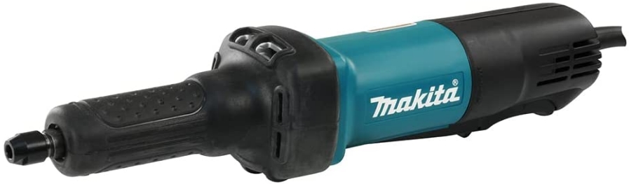
Makita GD0600 Die Grinder Instruction Manual
makita GD0600 Die Grinder Instruction Manual

Explanation of general view
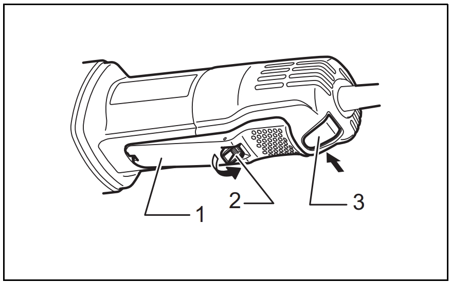


- Switch lever
- Lock-off lever
- Lock button
- Wrench 13
- Collet nut
- Side handle
SPECIFICATIONS
| Model | GD0600 | |
| Max. collet capacity | 6 mm or 6.35 mm (1/4”) | |
| Wheel Point | Max. wheel diameter | 38 mm |
| Max. mandrel (shank) length | 46 mm | |
| Rated speed (n) / No load speed (n0) | 25,000 min-1 | |
| Overall length | 358 mm | |
| Net weight | 1.7 kg | |
| Safety class | /II | |
- Due to our continuing program of research and development, the specifications herein are subject to change without notice.
- Specifications may differ from country to country.
- Weight according to EPTA-Procedure 01/2003
Intended use
The tool is intended for grinding ferrous materials or deburring castings.
Power supply
The tool should be connected only to a power supply of the same voltage as indicated on the nameplate, and can only be operated on single-phase AC supply. They are double-insulated and can, therefore, also be used from sockets without earth wire.
General Power Tool Safety Warnings
WARNING Read all safety warnings and all instructions. Failure to follow the warnings and instructions may result in electric shock, fire and/or serious injury.
Save all warnings and instructions for future reference.
DIE GRINDER SAFETY WARNINGS
Safety Warnings Common for Grinding Operation:
- This power tool is intended to function as a grinder. Read all safety warnings, instructions, illustrations and specifications provided with this power tool. Failure to follow all instructions listed below may result in electric shock, fire and/or serious injury.
- Operations such as sanding, wire brushing, polishing or cutting-off are not recommended to be performed with this power tool. Operations for which the power tool was not designed may create a hazard and cause personal injury.
- Do not use accessories which are not specifically designed and recommended by the tool manufacturer. Just because the accessory can be attached to your power tool, it does not assure safe operation.
- The rated speed of the accessory must be at least equal to the maximum speed marked on the power tool. Accessories running faster than their rated speed can break and fly apart.
- The outside diameter and the thickness of your accessory must be within the capacity rating of your power tool. Incorrectly sized accessories cannot be adequately controlled.
- The arbour size of accessories must properly fit the collet of the power tool. Accessories that do not match the mounting hardware of the power tool will run out of balance, vibrate excessively and may cause loss of control.
- Mandrel mounted accessories must be fully inserted into the collet or chuck. If the mandrel is insufficiently held and/or the overhang of the wheel is too long, the mounted accessory may become loose and be ejected at high velocity.
- Do not use a damaged accessory. Before each use inspect the accessory such as abrasive wheels for chips and cracks. If power tool or accessory is dropped, inspect for damage or install an undamaged accessory. After inspecting and installing an accessory, position yourself and bystanders away from the plane of the rotating accessory and run the power tool at maximum noload speed for one minute. Damaged accessories will normally break apart during this test time.
- Wear personal protective equipment. Depending on application, use face shield, safety goggles or safety glasses. As appropriate, wear dust mask, hearing protectors, gloves and workshop apron capable of stopping small abrasive or workpiece fragments. The eye protection must be capable of stopping flying debris generated by various operations. The dust mask or respirator must be capable of filtrating particles generated by your operation. Prolonged exposure to high intensity noise may cause hearing loss.
- Keep bystanders a safe distance away from work area. Anyone entering the work area must wear personal protective equipment. Fragments of workpiece or of a broken accessory may fly away and cause injury beyond immediate area of operation.
- Hold power tool by insulated gripping surfaces only, when performing an operation where the cutting accessory may contact hidden wiring or its own cord. Cutting accessory contacting a “live” wire may make exposed metal parts of the power tool “live” and could give the operator an electric shock.
- Always hold the tool firmly in your hand(s) during the start-up. The reaction torque of the motor, as it accelerates to full speed, can cause the tool to twist.
- Use clamps to support workpiece whenever practical. Never hold a small workpiece in one hand and the tool in the other hand while in use.
Clamping a small workpiece allows you to use your hand(s) to control the tool. Round material such as dowel rods, pipes or tubing have a tendency to roll
while being cut, and may cause the bit to bind or jump toward you. - Position the cord clear of the spinning accessory.
If you lose control, the cord may be cut or snagged and your hand or arm may be pulled into the spinning accessory. - Never lay the power tool down until the accessory has come to a complete stop. The spinning accessory may grab the surface and pull the power tool out of your control.
- After changing the bits or making any adjustments, make sure the collet nut, chuck or any other adjustment devices are securely tightened. Loose adjustment devices can unexpectedly shift, causing loss of control, loose
rotating components will be violently thrown. - Do not run the power tool while carrying it at your side. Accidental contact with the spinning accessory could snag your clothing, pulling the accessory into your body.
- Regularly clean the power tool’s air vents. The motor’s fan will draw the dust inside the housing and excessive accumulation of powdered metal may cause electrical hazards.
- Do not operate the power tool near flammable materials. Sparks could ignite these materials.
- Do not use accessories that require liquid coolants. Using water or other liquid coolants may result in electrocution or shock.
Kickback and Related Warnings
Kickback is a sudden reaction to a pinched or snagged rotating accessory. Pinching or snagging causes rapid stalling of the rotating accessory which in turn causes the
uncontrolled power tool to be forced in the direction opposite of the accessory’s rotation.
For example, if an abrasive wheel is snagged or pinched by the workpiece, the edge of the wheel that is entering into the pinch point can dig into the surface of the material causing the wheel to climb out or kick out. The wheel may either jump toward or away from the operator, depending on direction of the wheel’s movement at the point of pinching. Abrasive wheels may also break under these
conditions.
Kickback is the result of power tool misuse and/or incorrect operating procedures or conditions and can be avoided by taking proper precautions as given below.
- Maintain a firm grip on the power tool and position your body and arm to allow you to resist kickback forces. The operator can control kickback forces, if proper precautions are taken.
- Use special care when working corners, sharp edges etc. Avoid bouncing and snagging the accessory. Corners, sharp edges or bouncing have a tendency to snag the rotating accessory and cause loss of control or kickback.
- Do not attach a toothed saw blade. Such blades create frequent kickback and loss of control.
- Always feed the bit into the material in the same direction as the cutting edge is exiting from the material (which is the same direction as the chips are thrown). Feeding the tool in the wrong direction causes the cutting edge of the bit to climb out of the work and pull the tool in the direction of this feed.
Safety Warnings Specific for Grinding:
- Use only wheel types that are recommended for your power tool and only for recommended applications.
- Do not position your hand in line with and behind the rotating wheel. When the wheel, at the point of operation, is moving away from your hand, the possible kickback may propel the spinning wheel and the power tool directly at you.
Additional Safety Warnings:
- The tool is intended for use with bonded abrasive wheel points (grinding stones) permanently mounted on plain, unthreaded mandrel (shanks).
- Make sure the wheel is not contacting the workpiece before the switch is turned on.
- Before using the tool on an actual workpiece, let it run for a while. Watch for vibration or wobbling that could indicate poor installation or a poorly balanced wheel.
- Use the specified surface of the wheel to perform the grinding.
- Watch out for flying sparks. Hold the tool so that sparks fly away from you and other persons or flammable materials.
- Do not leave the tool running. Operate the tool only when hand-held.
- Do not touch the workpiece immediately after operation; it may be extremely hot and could burn your skin.
- Observe the instructions of the manufacturer for correct mounting and use of wheels. Handle and store wheels with care.
- Check that the workpiece is properly supported.
- If working place is extremely hot and humid, or badly polluted by conductive dust, use a shortcircuit breaker (30 mA) to assure operator safety.
- Do not use the tool on any materials containing asbestos.
- Always be sure you have a firm footing. Be sure no one is below when using the tool in high locations.
SAVE THESE INSTRUCTIONS.
WARNING:
DO NOT let comfort or familiarity with product (gained from repeated use) replace strict adherence to safety rules for the subject product. MISUSE or failure to follow the safety rules stated in this instruction manual may cause serious personal injury.
FUNCTIONAL DESCRIPTION
CAUTION:
Always be sure that the tool is switched off and unplugged before adjusting or checking function on the tool.
Switch action (Fig. 1)

CAUTION:
- Before plugging in the tool, always check to see that the switch lever actuates properly and returns to the “OFF” position when released.
- Do not pull the switch lever forcibly without pushing in the lock-off lever.
For tool with lock button
To prevent the switch lever from accidentally pulled, a lock-off lever is provided. To start the tool, pull the lock-off lever toward the operator and then pull the switch lever.
Release the switch lever to stop. For continuous operation, pull the switch lever and then push in the lock button. To stop the tool from the locked position, pull the switch lever fully, then release it.
For tool without lock button
To prevent the switch lever from accidentally pulled, a lock-off lever is provided. To start the tool, pull the lock-off lever toward the operator and then pull the switch lever.
Release the switch lever to stop.
ASSEMBLY
CAUTION:
Always be sure that the tool is switched off and unplugged before carrying out any work on the tool.
Installing or removing wheel point
Loosen the collet nut and insert the wheel point into the collet nut. Use one wrench to hold the spindle and the other one to tighten the collet nut securely. (Fig. 2)
The wheel point should not be mounted more than 10 mm from the collet nut. Exceeding this distance could cause vibration or a broken shaft. (Fig. 3)
To remove the wheel point, follow the installation procedure in reverse.
CAUTION:
Use the correct size collet cone for the wheel point which you intend to use.
OPERATION
Turn the tool on without the wheel point making any contact with the workpiece and wait until the wheel point attains full speed. Then apply the wheel point to the workpiece gently. To obtain a good finish, move the tool in the leftward direction slowly. (Fig. 4)

CAUTION:
Apply light pressure on the tool. Excessive pressure on the tool will only cause a poor finish and overloading of the motor.
MAINTENANCE
CAUTION:
- Always be sure that the tool is switched off and unplugged before attempting to perform inspection or maintenance.
- Never use gasoline, benzine, thinner, alcohol or the like. Discoloration, deformation or cracks may result.
To maintain product SAFETY and RELIABILITY, repairs, carbon brush inspection and replacement, any other maintenance or adjustment should be performed by Makita Authorized Service Centers, always using Makita replacement parts.
OPTIONAL ACCESSORIES
CAUTION:
These accessories or attachments are recommended for use with your Makita tool specified in this manual.
The use of any other accessories or attachments might present a risk of injury to persons. Only use accessory or attachment for its stated purpose.
If you need any assistance for more details regarding these accessories, ask your local Makita Service Center.
- Wheel points
- Collet cone set (3 mm, 6 mm, 1/4”, 1/8”)
- Wrench 13
- Vise holder
- Side handle set
Side handle (Fig. 5)

When using the side handle, remove the rubber protector, insert the side handle on the tool barrel as far as it will go and rotate it to the desired angle. Then tighten the handle firmly by turning clockwise.
CAUTION:
- When using the tool without handle, always install the rubber protector on the tool.
- When installing the rubber protector, always push it onto the tool until the protrusion inside the rubber fits to the grooves in the tool.
NOTE:
Some items in the list may be included in the tool package as standard accessories. They may differ from country to country.
Noise
The typical A-weighted noise level determined according to EN60745:
Sound pressure level (LpA): 74 dB (A)
Uncertainty (K): 3 dB (A)
The noise level under working may exceed 80 dB (A).
Wear ear protection.
Vibration
The vibration total value (tri-axial vector sum) determined according to EN60745:
Work mode: surface grinding
Vibration emission (ah,SG): 2.5 m/s2 or less
Uncertainty (K): 1.5 m/s
- The declared vibration emission value has been measured in accordance with the standard test method and may be used for comparing one tool with another.
- The declared vibration emission value may also be used in a preliminary assessment of exposure.
- The declared vibration emission value is used for main applications of the power tool. However if the power tool is used for other applications, the vibration emission value may be different.
WARNING:
- The vibration emission during actual use of the power tool can differ from the declared emission value depending on the ways in which the tool is used.
- Be sure to identify safety measures to protect the operator that are based on an estimation of exposure in the actual conditions of use (taking account of all parts of the operating cycle such as the times when the tool is switched off and when it is running idle in addition to the trigger time).
EC Declaration of Conformity
For European countries only
The EC declaration of conformity is included as Annex A to this instruction manual.