Dewalt DXAEPI1000 1000W Power Inverter Car Converter Instruction Manual
DEWALT DXAEPI1000 1000W Power Inverter Car Converter Instruction Manual


Failure to follow all instructions listed below may result in electric shock, fire and/or serious injury.
WARNING: This product or its power cord contains lead, a chemical known to the State of California to cause cancer and birth defect or other reproductive harm. Wash hands after handling. For more information go to www.P65Warnings.ca.gov.

Definitions: Safety Guidelines
The definitions below describe the level of severity for each signal word. Please read the manual and pay attention to these symbols.
DANGER: Indicates an imminently hazardous situation which, if not avoided, will result in death or serious injury.
WARNING: Indicates a potentially hazardous situation which, if not avoided, could result in death or serious injury.
CAUTION: Indicates a potentially hazardous situation which, if not avoided, may result in minor or moderate injury.
NOTICE: Indicates a practice not related to personal injury which, if not avoided, may result in property damage.
IF YOU HAVE ANY QUESTIONS OR COMMENTS ABOUT THIS WALT TOOL, CALL US TOLL FREE AT: 1-888-394-3392.
1000 Watt Power Inverter
The DXAEPI1000 1000 Watt Power Inverter is a DeWALT 1000W power inverter configured to supply continuous power in the form of two 120 volt AC outlets and three 5 volt USB power ports to run most
household or electronic appliances.
Important Safety Instructions
- Keep these instructions.
- Heed all warnings.
- Follow all instructions.
- Avoid dangerous environments. Don’t use the inverter in damp or wet locations. Don’t use the inverter in the rain or snow.
- Clean only with a dry cloth.
- Keep the inverter away from children. This is not a toy!
- Store indoors. When not in use, inverters should be stored indoors in dry, and high or locked-up places – out of the reach of children.
- Always turn the inverter off by pressing the on/off button, then disconnecting it from the DC source when not in use.
- Only use attachments/accessories specified by the manufacturer.
- Check for damaged parts. Any part that is damaged should be properly repaired or replaced by manufacturer, unless otherwise indicated elsewhere in this instruction manual before further use.
Servicing is required when the apparatus has been damaged in any way, such as power-supply cord or plug is damaged, liquid has been spilled or objects have fallen into the apparatus, the apparatus has been exposed to rain or moisture, does not operate normally, or has been dropped. Contact the manufacturer at 1-888-394-3392 for more information. - Apparatus shall not be exposed to dripping or splashing and no
objects filled with liquids shall be placed on the apparatus. - Un refroidissement approprié est essentiel lors de l’utilisation de l’onduleur. Ne placez pas l’appareil près de la bouche d’aération véhicule ou en plein soleil.
READ ALL INSTRUCTIONS
Specific Safety Instructions for Inverters WARNING – To reduce the risk of electric shock:
- Do not connect to AC distribution wiring.
- Do not make any electrical connections or disconnections in areas designated as IGNITION PROTECTED. This includes DC cigarette lighter type plug connection. This unit is NOT approved for ignition protected areas.
- NEVER immerse the unit in water or any other liquid, or use when wet.
- Do not insert foreign objects into the inverter’s outlets.
- Do not attach USB hubs or more than one personal electronic device to each USB Port.
- Extension cords. Make sure your extension cord is in good condition. When using an extension cord, be sure to use one heavy enough to carry the current your product will draw. An undersized cord will cause a drop in line voltage resulting in loss of power and overheating.
The following table shows the correct size to use depending on cord length and nameplate ampere rating. If in doubt, use the next heavier gauge. The smaller the gauge number, the heavier the cord.
MINIMUM GAGE FOR CORD SETS
Volts Total Length of Cord in Feet 120V 0-25 26-50 51-100 101-150\ (0-7.6m) (7.6-15.2m) (15.2-30.4m) (30.4-45.7m) 240V 0-50 51-100 101-200 201-300
(0-15.2m) (15.2-30.4m) (30.4-60.9m) (60.9-91.4m) Ampere Rating Extension Cord Length
More Not more 0’-25’ 26’-50’ 51 ’-100 ’ 101’ -150 ’
Than Than American Wire Gage (AWG)
0 – 6 18 16 16 14 6 – 10 18 16 14 12 10 – 12 16 16 14 12 12 – 16 14 12 Not Recommended
Outdoor use extension cords.
When an appliance plugged into this unit is used outdoors, use only extension cords intended for use outdoors and so marked. Note that this inverter is not intended to be used outdoors.
WARNING – To reduce the risk of fire:
- Do not operate near flammable materials, fumes or gases.
- Do not expose to extreme heat or flames.
CAUTION – To reduce the risk of injury or property damage: - When using this unit in a vehicle, check the vehicle owner’s manual for maximum power rating and recommended output. Do not install in engine compartment — install in a well ventilated area.
- Disconnect appliance plug from inverter outlet before working on the appliance.
- Do not attempt to connect or set up the inverter or its components while operating your vehicle. Not paying attention to the road may result in a serious accident.
- Always use the inverter where there is adequate ventilation. Do not block ventilation slots.
- Always turn the inverter off by disconnecting it from the power source when not in use.
- Make sure the nominal powering voltage is 12 volts
- Reverse polarity connection may result in a blown fuse and may cause permanent damage to the inverter. Connecting the device with reverse polarity will void your warranty.
- Keep in mind that this inverter will not operate high wattage appliances or equipment that produces heat, such as coffee makers, hair dryers, microwave ovens and toasters.
- Do not open the inverter — there are no user-serviceable parts inside. Opening the inverter will void manufacturer’s warranty.
- Do not use this inverter with medical devices. It is not tested for medical applications.
- Do not use this inverter on a watercraft. It is not qualified for marine applications.
- Follow these instructions and those published by battery manufacturer and the manufacturer of any equipment you intend to use with this unit. Review cautionary markings on these products and on the
engine. - Install and operate the inverter only as described in this Instruction Manual.
CAUTION – To reduce the risk of property damage:
- The Power Inverter must be connected only to batteries with a nominal output voltage of 12 volts. The unit will not operate from a 6 volt battery and will sustain permanent damage if connected to a 24 volt battery.
- Always connect the inverter to the 12 volt DC power source before plugging any devices into the unit.
- The standard North American 120 volt AC and USB outlets allow simultaneous operation of multiple devices. Simply plug the equipment into the unit and operate normally
- Ensure that the wattage of all equipment simultaneously plugged into the inverter does not exceed 1000 watts continuous or the unit may overheat and shut down.
CAUTION – Rechargeable devices - Certain rechargeable devices are designed to be charged by plugging them directly into an AC receptacle. These devices may damage the inverter or the charging circuit.
- When using a rechargeable device, monitor its temperature for the initial ten minutes of use to determine if it produces excessive heat.
- If excessive heat is produced, this indicates the device should not be used with this inverter.
- This problem does not occur with most of the battery-operated equipment. Most of these devices use a separate charger or transformer that is plugged into an AC receptacle.
- The inverter is capable of running most chargers and transformers.
CAUTION – Incompatible products: Certain products contain power supplies or circuits that are not compatible with an inverter using a modified sine wave output (such as this inverter) and may be damaged by using this inverter. properly, the instruction manual for your product could state this. If in doubt, you should contact your product manufacturer PRIOR TO USE. Some products must be powered from a pure sine wave power source, such as standard household power, or a “pure sine wave” inverter in order to function properly.
Your product could be damaged by this inverter if it contains: - Microwave ovens;
- Transformerless battery chargers
- Capacitive coupled power supplies If an incompatible product is used with this inverter:
- The product might not operate at all, with no indication of failure. The product fuse might open as a result of trying to use it with the inverter.
- The product might exhibit unusual operation (such as, intermittent operation, buzzing, and the like.)
NOTES:
A. Some laptop computers may not operate with this inverter.
B. Some USB-powered household electronics will not operate with these USB Ports. Check the manual of the corresponding electronic device to confirm that it can be used with this type of
USB Port.
WARNING: If the product does not operate normally, to reduce the risk of injury or property damage, turn the product off immediately and unplug it from the inverter.
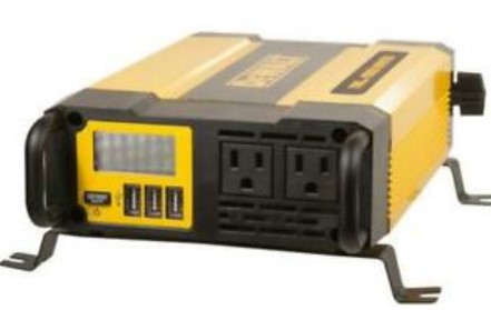
Components (Fig. 1)
Front
A. LCD display
B. USB ports
C. Power button
D. USB power/fault indicators
E. Three-prong 120V AC outlets
F. Mounting brackets shown with and without protective rubber grommets (4 of each)
Back
G. Negative (black) cap
H. Negative (black) cable post
I. Negative (black) post groove
J. High-speed Cooling Fan
K. Positive (red) post groove
L. Positive (red) cable post
M. Positive (red) cap Accessories
N. Battery Clips with cables and slide-in connectors
O. Installation cable set
P. Wing nuts and bolts for convenient installation
Q. Bolt (x2)
R. Washer (x2)
S. Wing Nut (x2)

How This Inverter Works
This inverter is an electronic device that converts low voltage DC (direct current) electricity from a battery to 120 volts AC (alternating current) household power. It converts power in two stages. The first stage is
a DC-to-DC conversion process that raises the low voltage DC at the inverter input to 145 volts DC. The second stage is a MOSFET bridge stage that converts the high voltage DC into 120 volts, 60 Hz AC.

Power Inverter Output Waveform
The AC output waveform of this inverter is known as a modified sine wave. It is a stepped waveform that has characteristics similar to the sine wave shape of utility power. This type of waveform is suitable for
most AC loads, including linear and switching power supplies used in electronic equipment, transformers, and small motors.

Rated Versus Actual Current Draw of Equipment
Most electrical tools, appliances, electronic devices and audio/visual equipment have labels that indicate the power consumption in amps or watts. Be sure that the power consumption of the item to be operated
is below 1000 watts. If the power consumption is rated in amps AC, simply multiply by the AC volts (120) to determine the wattage.
Resistive loads are the easiest for the inverter to run; however, it will not run larger resistive loads (such as electric stoves and heaters), which require far more wattage than the inverter can deliver. Inductive
loads (such as TVs and stereos) require more current to operate than do resistive loads of the same wattage rating.
Power Source Requirements
Your inverter will operate from input voltages between 11 and 15 volts DC. If the input voltage drops below 10 volts DC, the inverter will shut down. This feature protects the battery from being completely discharged.
The inverter will also shut down if the input voltage exceeds 15.6 volts. This protects the inverter against excessive input voltage. Although the inverter has built-in protection against over voltage, it may still be damaged if the input voltage exceeds 15 volts.
Your inverter is engineered to have standard electrical and electronic equipment directly connected to it in the manner described in the “Installation” section of this Instruction Manual. Do not connect the inverter to household or RV AC distribution wiring. Do not connect the inverter to any AC load circuit in which the neutral conductor is connected to ground (earth) or to the negative of the DC (battery) power source.
Inductive loads, such as TVs and stereos, require more current to operate than resistive loads of the same wattage rating. Induction motors, as well as some TVs, may require two to six times their rated wattage to start up. Because these inverters have a peak watt power rating, many such appliances and tools may be safely operated. The equipment that needs the highest starting wattage are pumps and compressors that start under load. This equipment can be safely tested. If an overload is detected, the inverter will simply shut down until the overload situation is corrected. Use the power button to turn off the inverter, then on again to reset it.

- Exceeding recommended voltage limits will void manufacturer’s warranty.
- The Power Inverter must be connected only to batteries with a nominal output voltage of 12 volts. The unit will not operate from a 6 volt battery and will sustain permanent damage if connected to a 24 volt battery.
- Reverse polarity connection will result in a blown fuse and may cause permanent damage to the inverter.
Protective Features
The inverter monitors the following conditions:
Input Voltage Too Low: This condition is not harmful to the inverter, but could damage the power source, so the inverter will automatically shut down when input voltage drops below 10.5 ± 0.5 volts DC.
Input Voltage Too High:
The inverter will automatically shut down when DC input voltage exceeds 16 ± 0.5 volts, as this can harm the unit.
Thermal Shutdown Protection:
The inverter will automatically shut down when the unit becomes overheated.
Overload/Short Circuit Protection:
The inverter will automatically shut down when an overload or short circuit occurs.
Refer to “Power and Fault Indicators on the LCD Display” for an explanation of the icons that indicate a fault condition before shutdown.
To restart the unit, simply unplug all devices plugged into the inverter; disconnect the inverter from any 12 volt DC power source; then reconnect the inverter BEFORE plugging the appliance(s) back in.
Power and Fault Indicators on the LCD Display
| Indicates that the unit is connected properly and is ready to use. The AC outlet icon and USB icon will light solid and the Digital Readout shows “0W”. The bars on the Battery Icon represent the voltage level of the connecte power source. |

| Indicates that the unit is functioning normally. The AC outlet icon and USB icon will light solid and the Digital Readout shows the total output wattage of AC outlets. The bars on the Battery Icon represent the voltage level of the connected power source. | |
| This indicates an input voltage too low fault condition. The fault icon and the empty battery icon will light solid and the unit will emit three beeps every five seconds. Refer to the following section for an explanation. | |
| This indicates an input voltage too high fault condition. The fault icon and the full battery icon will light solid and the unit will emit three beeps every five seconds. Refer to the following section for an explanation. | |
| This indicates a thermal fault condition. The fault icon and the overheat icon will light solid and the bars on the Battery Icon represent the voltage level of the connected power source. The unit will emit three beeps every five seconds. Refer to the following section for an explanation. |


| This indicates a USB fault condition, and displays when the USB load exceeds capacity. The USB icon will flash and the Digital Readout shows the total output wattage of AC outlets. The fault icon and the AC outlet icon will light solid and the bars on the Battery Icon represent the voltage level of the connected power source. The unit will emit three beeps every five seconds. | |
| This indicates an overload or short circuit fault condition. The AC outlet icon will flash and the Digital Readout shows 0W. The fault icon and the USB icon will light solid and the bars on the Battery Icon represent the voltage level of the connected power source. The unit will emit three beeps every five seconds. Refer to the following section for an explanation. |


Installation
Your inverter will provide you with continuous electrical power when powered by a reliable 12 volt DC source, such as a vehicle battery or a multiple battery configuration. This manual does not describe all of
the possible configurations.
Mounting the Inverter
Tools Required: four BA4x14 screws in a set and Philips head screwdriver (NOT supplied).
The inverter comes equipped with mounting brackets for long-term installation. The manufacturer recommends using BA4x14 screws
in a set with a standard Philips head screwdriver (none of these are supplied). User may choose to use different screws appropriate to the mounting surface.
Secure the inverter to a flat surface, observing all cautions regarding installation found in this manual.

Operating Environment
For best operating results, your inverter should be placed on a flat\ surface, such as the ground, car floor or seat, or other solid surface to help diffuse the heat that is generated. Position the inverter as close
to the DC power source as possible.
The inverter should only be operated in locations that meet the following criteria:
DRY – Do not allow water and/or other liquids to come into contact with the inverter.
COOL – Surrounding air temperature should ideally be 50-68°F (10- 20°C). Do not place the inverter on or near a heating vent or any piece of equipment that is generating heat above room temperature. Keep the inverter out of direct sunlight.
VENTILATED – Allow at least three inches of clearance from other objects to ensure free air circulation around the inverter. Never place items on or over the inverter during operation.
SAFE – Do not locate inverters in an area, room or compartment where explosives or flammable fumes might be present, such as engine rooms, engine compartments, and boats or small, unvented battery compartments.
Connecting the Inverter
The inverter must be connected only to batteries with a nominal output voltage of 12 volts. The unit will not operate from a 6 volt battery and will sustain permanent damage if connected to a 24 volt battery.
The standard North American 120 volt AC outlets and USB charging ports allow simultaneous operation of multiple devices. Simply plug the equipment into the unit and operate normally. Ensure that the wattage
of all equipment simultaneously plugged into the unit does not exceed 1000 watts continuous.
Connection to Power Source
The Power Inverter comes equipped Battery Clips for connection to CONNECTING TO A POWER SOURCE USING THE PROVIDED
BATTERY CLIPS WITH SLIDE-IN CONNECTORS
Use the provided Battery Clips (with cables and slide-in connectors) to connect the Power Inverter directly to the 12 volt power source as follows:
- Check to make sure that the inverter is turned off and no flammable fumes are present in the installation area.
- Turn the red plastic cap (counterclockwise) on the inverter’s positive
(+) cable post and remove. Attach the positive connector at the end of the red battery clip cable into the groove of the positive (+) cable post. Replace the cap and turn clockwise to secure. Do not over-tighten. - Connect the red battery clip to the POSITIVE terminal of the battery.
- Turn the black plastic cap (counterclockwise) on the inverter’s negative (–) cable post and remove. Attach the negative connector at the end of the black battery clip cable into the groove of thea power source.
negative (–) cable post. Replace the cap and turn clockwise to secure. Do not over-tighten. - Connect the black battery clip to the NEGATIVE terminal of the battery.
- Make sure that all connections between cables and terminals are secure.
- Press the power button to turn the inverter on. A beep will sound, the backlit LCD and the USB power/fault indicators will activate to indicate the inverter is operating properly and the 120 volt AC outlets are ready to power appliances that draw up to 1000W continuous and USB outlets up to 3.1A.
Note: Refer to “Power and Fault Indicators on the LCD Display” for an explanation of the operating and fault icons. If a fault icon appears, refer to the “Protective Features” section and the “Troubleshooting”
section of this manual.
DIRECT HARDWIRING TO POWER SOURCE (OPTIONAL CONNECTION METHOD; HARDWARE NOT INCLUDED)
Use #8 AWG wire if the inverter to power source connection is 4 feet or less. For cable lengths up to 10ft use #6 AWG wire.* In either case, protect the positive (+) wire from shorts by installing a 150 amp fuse
or circuit breaker close to the DC power source (battery) terminal.
The cable, fuse holder and fuse (not supplied) can be purchased at an electrical supply company. Manufacturer provides the installation cable set (refer to the “Installation” section of this manual).
*For cable lengths exceeding 10 feet from inverter to battery, contact manufacturer for additional information.
- Check to make sure that the inverter is turned off and no flammable fumes are present in the installation area.
- Identify the positive (+) and negative (–) DC power source (battery) terminals.
- Install a fuse holder or breaker close to the positive (+) terminal of the DC source (battery).
- Connect a length of wire on one side of the fuse holder or circuit breaker. Connect the other end of the wire to the positive (+, red) O-ring of the supplied cable set, securing them using the supplied bolt, washer and the wing nuts.
- Connect a length of wire on one side of the negative (–) DC power source (battery) terminal. Connect the other end of the wire to the negative (–, black) O-ring of the supplied cable set, securing them
using the supplied bolt, washer and the wing nuts. - Connect a short length of wire to the other terminal of the fuse holder or circuit breaker. Mark it “positive” or “+”.
- Connect the free end of the fuse or breaker wire to the positive (+) terminal of the DC power source (battery).
- Insert a fuse appropriate to the inverter in the fuse holder.
- Check to make sure the power button is turned off.
- Turn the red plastic cap on the inverter’s positive (+) cable post (counterclockwise) and remove. Attach the positive slide-in connector at the end of the supplied red cable set into the groove of the positive (+) cable post. Replace the cap and turn clockwise to secure. Do not over-tighten.
- Turn the black plastic cap on the inverter’s negative (–) cable post (counterclockwise) and remove. Attach the negative slide-in connector at the end of the supplied black cable set into the groove of the negative (–) cable post. Replace the cap and turn clockwiseb to secure. Do not over-tighten.
- Make sure that all connections between cables and terminals are secure.
- Press the power button to turn the inverter on. A beep will sound, the backlit LCD and the USB power/fault indicators will activate to indicate the inverter is operating properly and the 120 volt AC outlets are ready to power appliances that draw up to 1000W continuous and USB outlets up to 3.1A. Refer to “Power and Fault Indicators on the LCD Display” for an explanation of the operating and fault icons. If a fault icon appears, refer to the “Protective Features” section and the “Troubleshooting” section of this manual.
- Test the inverter by turning it on and plugging in a 100 watt lamp or equipment. If the inverter is not operating properly, then rrefer to the “Protective Features” section and the “Troubleshooting”
section of this manual.
- The cable and fuse sizes given here are a general recommendation. You should always consult your National Electrical Code prior to beginning each specific installation.
- Loose connectors may cause overheated wires and melted insulation.
- Check to make sure you have not reversed the polarity. Damage due to reversed polarity is not covered by our warranty. Important Cable Information: Substantial power loss and reduced battery operating time results from inverters installed with cables that are not able to supply full power. Symptoms of low battery power can result from cables that are either excessively long or an insufficient gauge. Connection To Load
The Power Inverter is equipped with dual standard North American three-prong type outlets. Plug the cord from the equipment you wish to operate into the AC receptacle(s). Make sure the combined load
requirement of your equipment does not exceed maximum continuous power.
The Power Inverter is engineered to be connected directly to standard electrical and electronic equipment in the manner described above.
Do not connect the Power Inverter to household or RV AC distribution wiring. Do not connect the Power Inverter to any AC load circuit in
which the neutral conductor is connected to ground (earth) or to the negative of the DC (battery) source.
Operating Instructions
The two standard North American 120 volt AC outlets and three USB ports are ready to use once the inverter is properly connected to a functioning power source and the power button is turned on. They
allow simultaneous operation of multiple devices. Simply plug the 110/120 volt AC appliance into one of the inverter’s three-prong AC outlets and/or plug the USB-powered device into one of the inverter’s
USB charging ports and operate normally.
Notes:
A. Ensure that the wattage of all equipment simultaneously plugged into the inverter does not exceed 1000 watts continuous when connected using the supplied battery clips or direct hardwiring.
B. This inverter’s USB Charging Ports does not support data communication. It only provides a total of 3.1A (5V each) DC power to an external USB-powered device.
C. Not all mobile phones are provided with a charging cable, they are normally data cables which are not supported by this device
– please check with your mobile phone manufacturer for the correct charging cable.
CAUTION –
To avoid the risk of property damage: Always connect the inverter to the 12 volt DC power source before plugging any devices into the unit.
Care and Maintenance STORAGE
- Ideal storage temperature range is 0-35°C (32-104°F).
- Store and use the inverter in a cool, dry place with adequate ventilation for all-around air circulation.
- Avoid locations that are exposed to heating units, radiators, direct sunlight, or excessive humidity or dampness.
Troubleshooting
Specific AC Outlet Problems
When the 120V AC outlets are in use, the unit will monitor for the following fault conditions: thermal fault, low and high battery voltage fault, overload and short circuit (refer to the “Protective Features” section).
| Problem | Possible Solution |
| If a fault condition exists in either of the AC outlets, the LCD will display the fault condition and the AC Outlets will automatically shut down. Should this occur: | A. Disconnect all appliances from the unit and press the power button again to turn off the unit immediately. B. Allow the unit to cool down for several minutes. C. Make sure the combined rating of all appliance simultaneously plugged into the inverter does not exceed 1000 watts continuous. D. Make sure the appliance cord(s) and plug(s) are not damaged. E. Assure there is adequate ventilation around the unit before proceeding. |
Specific USB Power Port Problems
When the USB ports are in use, the unit will monitor for the following USB fault conditions on all the USB ports: thermal fault, low battery voltage fault, overload and short circuit
| Problem | Possible Solution |
| Buzzing Sound In Audio Systems | Some inexpensive stereo systems and boom boxes make a buzzing sound when operated from the inverter, because the power supply in the electronic device does not properly filter the modified sine wave produced by the inverter. The only solution to this problem is to use a sound system that has a higher quality power supply. |
| Television Interference | The inverter is shielded to minimize interference with TV signals. However, in some instances, some interference may still be visible, especially when the TV signal is weak. Try the following to improve the picture: 1. Move the inverter as far away as possible from the TV set, the antenna, and the antenna cables. Use a short AC extension cord, if necessary. 2. Adjust the orientation of the antenna cables, and the TV power cord to minimize interference. 3. Make sure that the antenna feeding the TV provides an adequate (snow- free) signal and that high quality, shielded antenna cable is used. |
Specific USB Power Port Problems
When the USB ports are in use, the unit will monitor for the following USB fault conditions on all the USB ports: thermal fault, low battery voltage fault, overload and short circuit.
| Problem | Possible Solution |
| If a fault condition exists in either of the USB ports, the LCD will display the USB fault condition and the USB power/fault indicators shut off. In any of these cases, the USB ports will automatically shut down. Should this occur: | A. Disconnect the USB-powered device and press the power button again to turn off the unit immediately. B. Allow the unit to cool down for several minutes before attempting to use the USB ports again. C. If a fault occurs again, make sure that the total draw of all USB devices plugged into the USB ports does not exceed 3.1A. D. If an individual USB device is within specifications and the fault occurs, have the USB device checked for malfunction and do not continue to use it with these USB ports. |
Common Audio Problems
| Problem | Possible Solution |
| Buzzing Sound In Audio Systems | Some inexpensive stereo systems and boom boxes make a buzzing sound when operated from the inverter, because the power supply in the electronic device does not properly filter the modified sine wave produced by the inverter. The only solution to this problem is to use a sound system that has a higher quality power supply. |
| Television Interference | The inverter is shielded to minimize interference with TV signals. However, in some instances, some interference may still be visible, especially when the TV signal is weak. Try the following to improve the picture: 1. Move the inverter as far away as possible from the TV set, the antenna, and the antenna cables. Use a short AC extension cord, if necessary. 2. Adjust the orientation of the antenna cables, and the TV power cord to minimize interference. 3. Make sure that the antenna feeding the TV provides an adequate (snow- free) signal and that high quality, shielded antenna cable is used. |
Common Power Output Problems
| Problem | Possible Solution |
| Input voltage below
10.5 volts |
Recharge auto battery or check DC power supply. |
| Equipment being operated draws too much power | • Reduce load to maximum 1000 watts. |
| Inverter in thermal shutdown condition | Allow inverter to cool down. Ensure there is adequate ventilation around the unit and that the load is no more than 1000 watts for continuous operation. |
| AC output is shorted | Unplug the AC appliance. Disconnect the unit from any 12 volt DC power source. Check the appliance cord. |
Accessories
WARNING: Since accessories, other than those offered by DeWALT, have not been tested with this product, use of such accessories with this unit could be hazardous. To reduce the risk of injury, only DeWALT recommended accessories should be used with this product.
If you need assistance regarding accessories, please contact the manufacturer at 1-888-394-3392 or com.
Service Information
Whether you need technical advice, repair, or genuine factory replacement parts, contact the manufacturer at 1-888-394-3392 or
One Year Limited Warranty
The warranty of this product is covered by Baccus Global LLC (1-888-394-3392 or ). The manufacturer warrants this product against defects in material and workmanship for a period of one (1) year from the date of retail purchase by the original end-user purchaser (“Warranty Period”).
If there is a defect and a valid claim is received within the Warranty Period, the defective product can be repaired, replaced or refunded, without charge, in the following ways: (1) Return the product to the manufacturer for repair, replacement or refund at manufacturer’s option. Proof of purchase may be required by manufacturer. (2) Return the product to the retailer where product was purchased for an exchange (provided that the store is a participating retailer). Returns to retailer should be made within the time period of the retailer’s return policy for exchanges only (usually 30 to 90 days after the sale). Proof of purchase may be required. Please check with the retailer for their specific return policy regarding returns that are beyond the time set for exchanges. This warranty does not apply to: accessories, bulbs, fuses and batteries; defects resulting from normal wear and tear, accidents; damages sustained during shipping; alterations; unauthorized use or repair; neglect, misuse, abuse; and failure to follow instructions for care and maintenance for the product.
This warranty gives you, the original retail purchaser, specific legal rights and you may have other rights which vary in certain states or provinces. This product is not intended for commercial use.
90 DAY REFUND POLICY
If you are not completely satisfied with the performance of this product for any reason, you can return it within ninety (90) days from the date of purchase with a receipt for a full refund.
Please visit our website www.bacusglobal.com/register to register your new Baccus Global LLC product and to be kept up to date on new products and special offers
Specifications
| Maximum Power | 1000 watts continuous |
| Input | 12.8 V DC, 95A |
| AC Output | 120 volts AC, 60Hz |
| Output Waveform | Modified Sine Wave |
| USB Power Ports | 5V DC each (3.1A maximum) |
Manufactured and Imported by Baccus Global LLC, 621 NW 53rd St., Suite 450, Boca Raton, FL 33487 www.dewalt12volt.com 1-888-394-3392 Made in China
Copyright © 2021 Baccus Global, LLC. DEWALT® and the DEWALT Logo are trademarks of the DEWALT Industrial Tool Co., or an affiliate thereof and are used under license. The yellow/black color scheme is a trademark for DEWALT power tools & accessories