Schneider Electric PowerLogic HDPM6000 Series CT Models for High Accuracy and Split Core Variants Installation Guide
Schneider Electric PowerLogic HDPM6000 Series CT Models for High Accuracy and Split Core Variants

Safety Information
Important information
Read these instructions carefully and look at the equipment to become familiar with the device before trying to install, operate, service or maintain it. The following special messages may appear throughout this bulletin or on the equipment to warn of potential hazards or to call attention to information that clarifies or simplifies a procedure.

This is the safety alert symbol. It is used to alert you to potential personal injury hazards. Obey all safety messages that follow this symbol to avoid possible injury or death.
|
| DANGER indicates an hazardous situation which, if not avoided, will result in death or serious injury |

| WARNING indicates a hazardous situation which, if not avoided, could result in death or serious injury. |
CAUTION |
| CAUTION indicates a hazardous situation which, if not avoided, could result in minor or moderate injury. |
|
| NOTICE is used to address practices not related to physical injury. |
Please note
Electrical equipment should be installed, operated, serviced and maintained only by qualified personnel. No responsibility is assumed by Schneider Electric for any consequences arising out of the use of this material.
A qualified person is one who has skills and knowledge related to the construction, installation and operation of electrical equipment and has received safety training to recognize and avoid the hazards involved.
PowerLogic HDPM6000 Series CT Models for High Accuracy and Split-Core Variants (20A 4000A)
Safety Precautions
Installation, wiring, testing and service must be performed in accordance with all local and national electrical codes.
HAZARD OF ELECTRIC SHOCK, EXPLOSION, OR ARC FLASH
|
| RISK OF INJURY OR EQUIPMENT DAMAGE Do not apply current transducers to circuits having a phase-to-phase voltage greater than their voltage rating unless adequate additional insulation is applied between the primary conductor and the current transducers. equipment damage. |
Schneider Electric assumes no responsibility for damage of equipment or personal injury caused by products operated on circuits above their published ratings.
Introduction
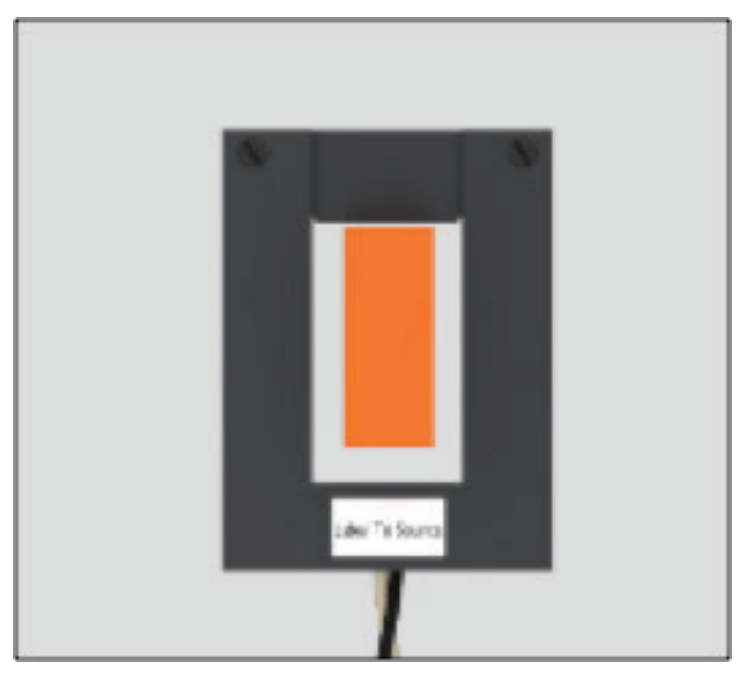
Schneider Electric PowerLogic High Accuracy and Split-Core Current Transducers (CTs) provide secondary voltage AC proportional to the primary (sensed) current. For use with the HDPM6000 platform only, these CTs provide a means to transform electrical service amperages to a voltage compatible with monitoring equipment.
These CTs range from 20A to 4000A voltage ratings with 0.2% to 1% accuracy.
Ordering Information
| Model Number | Description | Accuracy |
| SUN2 | ||
| METSEHDPM20A12H | 20A, High Accuracy Split-Core CT, 12′ lead | 0.2% |
| METSEHDPM20A30H | 20A, High Accuracy Split-Core CT, 30′ lead | 0.2% |
| SUN3 | ||
| METSEHDPM75A12H | 75A, High Accuracy Split-Core CT, 12′ lead | 0.2% |
| METSEHDPM75A4H | 75A, High Accuracy Split-Core CT, 30′ lead | 0.2% |
| METSEHDP150A12H | 150A, High Accuracy Split-Core CT, 12′ lead | 0.2% |
| METSEHDP150A30H | 150A, High Accuracy Split-Core CT, 30′ lead | 0.2% |
| SUN4 | ||
| METSEHDP300A12H | 300A, High Accuracy Split-Core CT, 12′ lead | 0.2% |
| METSEHDPM300A30H | 300A, High Accuracy Split-Core CT, 30′ lead | 0.2% |
| METSEHDPM400A12H | 400A, High Accuracy Split-Core CT, 12′ lead | 0.2% |
| METSEHDPM400A30H | 400A, High Accuracy Split-Core CT, 30′ lead | 0.2% |
| SUS4 | ||
| METSEHDPM150A12 | 150A, Split-Core CT, 12′ lead | 0.5% |
| METSEHDPM150A30 | 150A, Split-Core CT, 30′ lead | 0.5% |
| METSEHDPM150A60 | 150A, Split-Core CT, 60′ lead | 0.5% |
| METSEHDPM150A5 | 150A, Split-Core CT, HDPM6000S, 5″ lead with connector | 0.5% |
| METSEHDPM150A16 | 150A, Split-Core CT, HDPM6000B, 16″ lead | 0.5% |
| METSEHDPM300A12 | 300A, Split-Core CT, 12′ lead | 0.5% |
| METSEHDPM300A30 | 300A, Split-Core CT, 30′ lead | 0.5% |
| METSEHDPM300A60 | 300A, Split-Core CT, 60′ lead | 0.5% |
| METSEHDPM300A5 | 300A, Split-Core CT, HDPM6000S, 5″ lead with connector | 0.5% |
| METSEHDPM300A16 | 300A, Split-Core CT, HDPM6000B 16″ lead | 0.5% |
| METSEHDPM400A12 | 400A, Split-Core CT, 12′ lead | 0.5% |
| METSEHDPM400A30 | 400A, Split-Core CT, 30′ lead | 0.5% |
| METSEHDPM400A60 | 400A, Split-Core CT, 60′ lead | 0.5% |
| METSEHDPM400A5 | 400A, Split-Core CT, HDPM6000S, 5″ lead with connector | 0.5% |
| METSEHDPM400A16 | 400A, Split-Core CT, HDPM6000B 16″ lead | 0.5% |
| METSEHDPM600A12 | 600A, Split-Core CT, 12′ lead | 0.5% |
| METSEHDPM600A30 | 600A, Split-Core CT, 30′ lead | 0.5% |
| METSEHDPM600A60 | 600A, Split-Core CT, 60′ lead | 0.5% |
| METSEHDP600A5H | 600A, Split-Core CT, HDPM6000S, 5″ lead with connector | 0.5% |
| METSEHDP600A16H | 600A, Split-Core CT, HDPM6000B 16″ lead | 0.5% |
| SUSF | ||
| METSEHD150A12 | 150A, Split-Core CT, 1″x1″, 12′ lead | 1% |
| METSEHD150A30 | 150A, Split-Core CT, 1″x1″, 30′ lead | 1% |
| METSEHD150A60 | 150A, Split-Core CT, 1″x1″, 60′ lead | 1% |
| METSEHD300A12 | 300A, Split-Core CT, 1″x1″, 12′ lead | 1% |
| METSEHD300A30 | 300A, Split-Core CT, 1″x1″, 30′ lead | 1% |
| METSEHD300A60 | 300A, Split-Core CT, 1″x1″, 60′ lead | 1% |
| METSEHD300A12L | 300A, Split-Core CT, 2″x2″, 12′ lead | 1% |
| METSEHD300A30L | 300A, Split-Core CT, 2″x2″, 30′ lead | 1% |
| METSEHD300A60L | 300A, Split-Core CT, 2″x2″, 60′ lead | 1% |
| METSEHD400A12 | 400A, Split-Core CT, 1.25″x1.25″, 12′ lead | 1% |
| METSEHD400A30 | 400A, Split-Core CT, 1.25″x1.25″, 30′ lead | 1% |
| METSEHD400A60 | 400A, Split-Core CT, 1.25″x1.25″, 60′ lead | 1% |
| METSEHD400A12L | 400A, Split-Core CT, 2.5″x2.5″, 12′ lead | 1% |
| METSEHD400A30L | 400A, Split-Core CT, 2.5″x2.5″, 30′ lead | 1% |
| METSEHD400A60L | 400A, Split-Core CT, 2.5″x2.5″, 60′ lead | 1% |
| METSEHD600A12 | 600A, Split-Core CT, 3″x 3″, 12′ lead | 1% |
| METSEHD600A30 | 600A, Split-Core CT, 3″ x 3″, 30′ lead | 1% |
| METSEHD600A60 | 600A, Split-Core CT, 3″ x 3″, 60′ lead | 1% |
| METSEHD800A12 | 800A, Split-Core CT, 4″x 4″, 12′ lead | 1% |
| METSEHD800A30 | 800A, Split-Core CT, 4″ x 4″, 30′ lead | 1% |
| METSEHD800A60 | 800A, Split-Core CT, 4″ x 4″, 60′ lead | 1% |
| METSEHD1000A12 | 1000A, Split-Core CT, 4″x 4″, 12′ lead | 1% |
| METSEHD1000A30 | 1000A, Split-Core CT, 4″ x 4″, 30′ lead | 1% |
| METSEHD1200A12 | 1200A, Split-Core CT, 4″x 6″, 12′ lead | 1% |
| METSEHD1200A30 | 1200A, Split-Core CT, 4″ x 6″, 30′ lead | 1% |
| METSEHD1600A12 | 1600A, Split-Core CT, 4″x 6″, 12′ lead | 1% |
| METSEHD1600A30 | 1600A, Split-Core CT, 4″ x 6″, 30′ lead | 1% |
| METSEHD1600A12L | 1600A, Split-Core CT, 4.5″x 4.5″, 12′ lead | 1% |
| METSEHD1600A30L | 1600A, Split-Core CT, 4.5″ x 4.5″, 30′ lead | 1% |
| METSEHD2000A12 | 2000A, Split-Core CT, 4″x 6″, 12′ lead | 1% |
| METSEHD2000A30 | 2000A, Split-Core CT, 4″ x 6″, 30′ lead | 1% |
| METSEHD2000A12L | 2000A, Split-Core CT, 6″x 3″, 12′ lead | 1% |
| METSEHD2000A30L | 2000A, Split-Core CT, 6″ x 3″, 30′ lead | 1% |
| METSEHD3000A12 | 3000A, Split-Core CT, 4″x 4″, 12′ lead | 1% |
| METSEHD3000A30 | 3000A, Split-Core CT, 4″ x 4″, 30′ lead | 1% |
| METSEHD3000A12L | 3000A, Split-Core CT, 4″x 6″, 12′ lead | 1% |
| METSEHD3000A30L | 3000A, Split-Core CT, 4″ x 6″, 30′ lead | 1% |
| METSEHD3000A12XL | 3000A, Split-Core CT, 5″x 12″, 12′ lead | 1% |
| METSEHD3000A30XL | 3000A, Split-Core CT, 5″ x 12″, 30′ lead | 1% |
| METSEHD4000A12 | 4000A, Split-Core CT, 5″x 12″, 12′ lead | 1% |
| METSEHD4000A30 | 4000A, Split-Core CT, 5″ x 12″, 30′ lead | 1% |
Specifications
| Output at Rated Current | 0.25VAC |
| Accuracy | 0.2% (SUN2/SUN3/SUN4), 0.5% (SUS4) and 1% (SUSF) |
| Operating Temperature Range | -40 to 55 °C (-40 to 131 °F) |
| Storage Temperature Range | -50 to +70 °C (-58 to 158 °F) |
| Frequency Range | 50/60 Hz |
| Leads | B/W twisted pair 18 AWG, AWM, UL1015, 600V, 105 °C |
| Max. Voltage L-N Sensed Conductor | 600 VAC |
| Altitude of Operation | 2000 m max. |
| Humidity Range | 0 to 95% non-condensing |
| Continuous current rating factor | 1 |
| Installation Category | Cat III, Pollution Degree 2 |
| Agency Approvals | UL2808, CE |
Dimensions SUN2, SUN3, SUN4 & SUS4

| Model | W |
A Dimension | B Dimension | C Dimension |
| SUN2 | 0.4 in (10.17 mm) | 2.4 in (60.69 mm) | 1.65 in (41.91 mm) | 0.85 to 1.1 in (21.58 to 27.94 mm) |
| SUN3 | 0.7 in (17.80 mm) | 3.0 in (76.19 mm) | 2.4 in (60.96 mm) | 1.1 in (27.94 mm) |
| SUN4 | 1.25 in (31.75 mm) | 3.3 in (83.81 mm) | 3.1 in (78.74 mm) | 1.3 in (31.04 mm) |
| SUS4 | 1.25 in (31.75 mm) | 3.3 in (83.81 mm) | 3.1 in (78.74 mm) | 1.3 in (31.04 mm) |
SUSF

Busbar and Phase Orientation
- The white mark ensures orientation every time the top is attached.
- Typically, the white mark is on the top right side when looking at the product label.
- Refer to label for correct CT orientation.

Proper Size and Fitting
- The window of the CT should be big enough to fit the busbar without
excess space. - A split-core CT should not be oversized around the bus/conductor, resulting in an inaccurate/bad reading.
- The busbar should also be in the center of the CT window to allow the coils to energize evenly.

Installation
Installation must be performed by a qualified electrician. Turn off and lock out power to the primary circuit before installing these CTs. Use a properly rated voltage sensing device to confirm that power is off.
In any application where fault currents can exceed 20 times the rated current of the CT, use wire ties or similar fasteners to secure both sides of the I-bar to the CT housing.
NOTICE |
| INCORRECT POLARITY Align CT arrow to point in the direction of the power flow. Failure to follow this instruction can result in incorrect readings. |
Remove the screws (or push-pins) from the CT and take the top off.
- Slide the body of the CT over the busbar.
- Refer to label for correct CT orientation.
- Re-attach the top to the body of the CT, using the white mark to orient how the top will fit.
- Place the screws/push-pins back to secure the top to the CT.
- Once the CT is installed onto the busbar, terminate the leads to the metering device prior to turning on the power.

Schneider Electric
12345 SW Leveton Drive
Tualatin, OR 97062 USA
+1-503-598-4564
schneider-electric.com

© 2021 Schneider Electric. All Rights Reserved.
PowerLogic and Schneider Electric are trademarks or registered trademarks of Schneider Electric in France, the USA and other countries. Other companies’ trademarks are the property of their respective owners.
As standards, specifications, and designs change from time to time, please ask for confirmation of the information given in this publication.
Z208152-0C 08/2021
