Bosch GBH 36 V-EC Compact Professional Cordless Rotary Hammer Instruction Manual


GBH 36 V-EC Compact Professional
Original instructions


Personal safety
- Stay alert, watch what you are doing, and use common sense when operating a power tool. Do not use a power tool while you are tired or under the influence of drugs,
alcohol, or medication. A moment of inattention while operating power tools may result in serious personal injury. - Use personal protective equipment. Always wear eye protection. Protective equipment such as dust masks, non-skid safety shoes, hard hats, or hearing protection used for appropriate conditions will reduce personal injuries.
- Prevent unintentional starting. Ensure the switch is in the off-position before connecting to a power source and/or battery pack, picking up or carrying the tool. Carrying power tools with your finger on the switch or energizing power tools that have the switch on invites accidents
- Remove any adjusting key or wrench before turning the power tool on. A wrench or a key left attached to a rotating part of the power tool may result in personal injury.
- Do not overreach. Keep proper footing and balance at all times. This enables better control of the power tool in unexpected situations.
- Dress properly. Do not wear loose clothing or jewelry. Keep your hair, clothing, and gloves away from moving parts. Loose clothes, jewelry, or long hair can be caught in moving parts.
- If devices are provided for the connection of dust extraction and collection facilities, ensure these are connected and properly used. Use of dust collection can reduce dust-related hazards.
Power tool use and care - Do not force the power tool. Use the correct power tool for your application. The correct power tool will do the job better and safer at the rate at which it was designed.
- Do not use the power tool if the switch does not turn it on and off. Any power tool that cannot be controlled with the switch is dangerous and must be repaired.
- Disconnect the plug from the power source and/or the battery pack from the power tool before making any adjustments, changing accessories, or storing power tools. Such preventive safety measures reduce the risk of starting the power tool accidentally.
- Store idle power tools out of the reach of children and do not allow persons unfamiliar with the power tool or these instructions to operate the power tool. Power tools are dangerous in the hands of untrained users.
- Maintain power tools. Check for misalignment or binding of moving parts, breakage of parts, and any other condition that may affect the power tool’s operation. If damaged, have the power tool repaired before use. Many accidents are caused by poorly maintained power tools.
- Keep cutting tools sharp and clean. Properly maintained cutting tools with sharp cutting edges are less likely to bind and are easier to control.
- Use the power tool, accessories and tool bits, etc. in accordance with these instructions, taking into account the working conditions and the work to be performed. Use of the power tool for operations different from those intended could result in a hazardous situation.
Battery tool use and care - Recharge only with the charger specified by the manufacturer. A charger that is suitable for one type of battery pack may create a risk of fire when used with another battery pack.
- Use power tools only with specifically designated battery packs. Use of any other battery packs may create a risk of injury and fire.
- When the battery pack is not in use, keep it away from other metal objects, like paper clips, coins, keys, nails, screws, or other small metal objects, that can make a connection from one terminal to another. Shorting the battery terminals together may cause burns or a fire.
- Under abusive conditions, liquid may be ejected from the battery; avoid contact. If contact accidentally occurs, flush with water. If liquid contacts the eyes, additionally seek medical help. Liquid ejected from the battery may cause irritation or burns.
Service - Have your power tool serviced by a qualified repair person using only identical replacement parts. This will ensure that the safety of the power tool is maintained.
Hammer Safety Warnings
- Wear ear protectors. Exposure to noise can cause hearing loss.
- Use auxiliary handle(s), if supplied with the tool. Loss of control can cause personal injury.
- Hold power tool by insulated gripping surfaces, when performing an operation where the cutting accessory or fastener may contact hidden wiring. Cutting accessory and fasteners contacting a “live” wire may make exposed metal parts of the power tool “live” and could give the operator an electric shock.
- Use appropriate detectors to determine if utility lines are hidden in the work area or call the local utility company for assistance. Contact with electric lines can lead to fire and electric shock. Damaging a gas line can lead to an explosion. Penetrating a water line causes property damage.
- When working with the machine, always hold it firmly with both hands and provide a secure stance. The power tool is guided more securely with both hands.
- Secure the workpiece. A workpiece clamped with clamping devices or in a vice is held more secure than by hand.
- Always wait until the machine has come to a complete stop before placing it down. The tool insert can jam and lead to loss of control over the power tool.
- Do not open the battery. The danger of short-circuiting.
- In case of damage and improper use of the battery, vapors may be emitted. Ventilate the area and seek medical help in case of complaints. The vapors can irritate the respiratory system.
- Use the battery only in conjunction with your Bosch power tool. This measure alone protects the battery against dangerous overload.
- The battery can be damaged by pointed objects such as nails or screwdrivers or by force applied externally. An internal short circuit can occur and the battery can burn, smoke, explode or overheat.

Product Description and Specifications
Failure to follow the warnings and instructions may result in electric shock, fire, and/or serious injury.

While reading the operating instructions, unfold the graphics page for the machine and leave it open.
Intended Use
The machine is intended for hammer drilling in concrete, brick, and stone. It is also suitable for drilling without impact in wood, metal, ceramic, and plastic. Machines with electronic control and right/left rotation are also suitable for screwdriving.
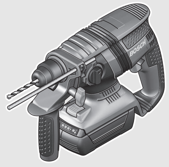
Product Features
The numbering of the product features refers to the illustration of the machine on the graphics page.
- Depth stop
- SDS-plus tool holder
- Dust protection cap
- Locking sleeve
- Vibration damper
- Handle (insulated gripping surface)
- Rotational direction switch
- On/Off switch
- Selector switch for drilling/hammer drilling
- Button for depth stop adjustment
- Wing bolt for adjustment of the auxiliary handle
- Battery pack*
- Battery unlocking button
- Temperature control indicator
- Battery charge-control indicator
- Button for charge-control indicator
- Auxiliary handle (insulated gripping surface)
- Keyless chuck*
- Front sleeve of the keyless chuck*
- Rear sleeve of the keyless chuck*
- Extraction sleeve of the dust extraction attachment*
- Clamping screw for the dust extraction attachment*.
- Depth stop of the dust extraction attachment*
- Telescopic pipe of the dust extraction attachment*
- Wing bolt of the dust extraction attachment*
- Guide pipe of the dust extraction attachment*
- Universal bit holder with SDS-plus shank*
*Accessories shown or described are not part of the standard delivery scope of the product. A complete overview of accessories can be found in our accessories program.
Technical Data
| Rotary Hammer | GBH 36 | V-EC Compact |
| Article number | 3 611 J03 R. | |
| Speed control | ● | |
| Right/left rotation | ● | |
| Rated voltage | V= | 36 |
| Rated power input | W | 430 |
| Output power | W | 320 |
| Impact rate | min-1 | 0 –4850 |
| Impact energy per stroke according to EPTA-Procedure 05/2009 | J | 1.8 |
| Speed | min-1 | 0 –1500 |
| Tool holder | SDS-plus | |
| Spindle collar diameter | mm | 48 |
| Drilling diameter, max.: – Concrete |
mm | 18 |
| – Steel | mm | 13 |
| – Wood | mm | 30 |
| max. Diameter screw | mm | 6 |
| Weight according to EPTA-Procedure 01/2003 * dependent on the battery pack being used |
kg | 2.9/3.5* |
Battery
Permitted ambient temperature
| – when charging | °C | 0…+45 |
| –during operation* | °C | –20…+50 |
| – during storage | °C | –20…+60 |
| Recommended batteries * Limited performance at temperatures |
<0 °C | GBA 36V x,xAh H-. |
Noise/Vibration Information
Measured sound values determined according to EN 60745.
Typically the A-weighted noise levels of the product are Sound pressure level 91 dB(A); Sound power level 102 dB(A). Uncertainty K =3 dB.
Wear hearing protection!
Vibration total values ah (triax vector sum) and uncertainty K
determined according to EN 60745:
Hammer drilling into concrete: ah = 16 m/s², K = 1.9 m/s²,
Drilling in metal: ah <2.5 m/s², K =1.5 m/s²,
Screwdriving without impact: ah <2.5 m/s², K = 1.5 m/s².
The vibration level given in this information sheet has been measured in accordance with a standardized test given in EN 60745 and may be used to compare one tool with another. It may be used for a preliminary assessment of exposure. The declared vibration emission level represents the main applications of the tool. However, if the tool is used for different applications, with different accessories or insertion tools or is poorly maintained, the vibration emission may differ. This may significantly increase the exposure level over the total working period.
An estimation of the level of exposure to vibration should also take into account the times when the tool is switched off or when it is running but not actually doing the job. This may significantly reduce the exposure level over the total working period. Identify additional safety measures to protect the operator from the effects of vibration such as: maintaining the tool and the accessories, keeping the hands warm, and organization of work patterns.

We declare under our sole responsibility that the product described under “Technical Data” is in conformity with the following standards or standardization documents: EN 60745 according to the provisions of the directives 2011/65/EU, 2004/108/EC, 2006/42/EC. Technical file (2006/42/EC) at: Robert Bosch GmbH, PT/ETM9, D-70745 Leinfelden-Echterdingen
| Henk Becker | Helmut Heinzelmann |
| Executive Vice President | Head of Product Certification |
| Engineering | PT/ETM9 |

Robert Bosch GmbH, Power Tools Division
D-70745 Leinfelden-Echterdingen
Leinfelden, 16.10.2013.
Assembly
Battery Charging
- Use only the battery chargers listed on the accessories page. Only these battery chargers are matched to the lithium-ion battery of your power tool.
Note: The battery is supplied partially charged. To ensure the full capacity of the battery, completely charge the battery in the battery charger before using your power tool for the first time.
The lithium-ion battery can be charged at any time without reducing its service life. Interrupting the charging procedure does not damage the battery. The lithium-ion battery is protected against deep discharging by the “Electronic Cell Protection (ECP)”. When the battery is empty, the machine is switched off by means of a protective circuit: The inserted tool no longer rotates. - Do not continue to press the On/Off switch after the machine has been automatically switched off. The battery can be damaged.
Removing the battery
The battery 12 is equipped with two locking levels that should prevent the battery from falling out when pushing the battery unlocking button 13 unintentionally. As long as the battery is inserted in the power tool, it is held in position by means of a spring.

To remove the battery 12:
– Push the battery against the base of the power tool (1.) and at the same time press the battery unlocking button 13 (2.).
– Pull the battery out of the power tool until a red stripe becomes visible (3.).
– Press the battery unlocking button 13 again and pull out the battery completely.
Battery Charge-control Indication
The three green LEDs of the battery charge-control indicator 15 indicate the charge condition of the battery 12. For safety reasons, it is only possible to check the status of the charge condition when the machine is at a standstill.
–Push-button 16 to indicate the charge condition (also possible when the battery is removed). The battery charge control indicator automatically goes out after approx. 5seconds.
| LED | Capacity |
| Continuous lighting 3 x green | ≥2/3 |
| Continuous lighting 2 x green | ≥1/3 |
| Continuous lighting 1 x green | <1/3 |
| Flashing light 1 x green | Reserve |
When no LED lights up after pushing button 16, then the battery is defective and must be replaced.
During the charging procedure, the three green LEDs light up one after the other and briefly go out. The battery is fully charged when the three green LEDs light up continuously. The three LEDs go out again approx. 5 minutes after the battery has been fully charged.
The battery is equipped with an NTC temperature control which allows charging only within a temperature range of between 0 °C and 45 °C. A long battery service life is achieved in this manner.
Auxiliary Handle
- Operate your machine only with the auxiliary handle 17.
Changing the position of the auxiliary handle (see figure A) The auxiliary handle 17 can be set to any position for a secure and low-fatigue working posture.
– Turn the wing bolt for adjustment of the auxiliary handle 11 in an anticlockwise direction and set the auxiliary handle 17 to the required position. Then tighten the wing bolt 11 again in a clockwise direction.Adjusting the Drilling Depth (see figure B)
The required drilling depth X can be set with depth stop 1.
– Press the button for the depth stop adjustment 10 and insert the depth stop into the auxiliary handle 17. The knurled surface of the depth stop 1 must face downward.
– Insert the SDS-plus drilling tool to the stop into the SDS-plus tool holder 2. Otherwise, the movability of the SDS-plus drilling tool can lead to incorrect adjustment of the drilling depth.
– Pull out the depth stop until the distance between the tip of the drill bit and the tip of the depth stop correspond with the desired drilling depth X.
Selecting Drill Chucks and Tools
For hammer drilling, SDS-plus tools are required that are inserted in the SDS-plus drill chuck. For drilling without impact in wood, metal, ceramic, and plastic as well as for screwdriving, tools without SDS-plus are used (e.g., drills with cylindrical shank). For these tools, a keyless chuck or a key-type drill chuck are required.
Changing the Keyless Chuck
To work with tools without SDS-plus (e.g., drills with cylindrical shank), a suitable drill chuck must be mounted (key type drill chuck or keyless chuck, accessories).
Inserting the Keyless Chuck (see figure C)
– Clean the shank end of the adapter shank and apply a light coat of grease.
– Insert the keyless chuck 18 with the adapter shank into the tool holder with a turning motion until it automatically locks.
– Check the locking effect by pulling the keyless chuck.
Removing the Keyless Chuck
– Push the locking sleeve 4 toward the rear and pull out the
keyless chuck18.
Changing the Tool
The dust protection cap 3 largely prevents the entry of drilling dust into the tool holder during operation. When inserting the tool, take care that the dust protection cap 3 is not damaged.
- A damaged dust protection cap should be changed immediately. We recommend having this carried out by an after-sales service.
Inserting SDS-plus Drilling Tools (see figure D)
The SDS-plus drill chuck allows for simple and convenient changing of drilling tools without the use of additional tools.
– Clean and lightly grease the shank end of the tool.
– Insert the tool in a twisting manner into the tool holder until it latches itself.
– Check the latching by pulling the tool.
As a requirement of the system, the SDS-plus drilling tool can move freely. This causes a certain radial run-out at no-load, which has no effect on the accuracy of the drill hole, as the drill bit centers itself upon drilling.
Removing SDS-plus Drilling Tools (see figure E)
– Push back the locking sleeve 4 and remove the tool.
Inserting Drilling Tools without SDS-plus (see figure F)
Note: Do not use tools without SDS-plus for hammer drilling or chiseling! Tools without SDS-plus and their drill chucks are damaged by hammer drilling or chiseling.
– Insert the keyless chuck 18.
– Hold the rear sleeve 20 of the keyless chuck 18 and turn the front sleeve 19 in an anticlockwise direction until the tool can be inserted. Insert the tool.
– Tightly hold the rear sleeve of the keyless chuck 18 and firmly turn the front sleeve clockwise by hand until the locking action is no longer heard. This automatically locks the drill chuck.
– Check the tight seating by pulling the tool.
Note: If the tool holder was opened to the stop, then a latching noise possibly may be heard while closing the tool holder and the tool holder will not close. In this case, turn the front sleeve 19 once in an anticlockwise direction. Afterward, the tool holder can be closed (tightened). – Turn the mode selector switch 11 to the “drilling” position.
Removing Drilling Tools without SDS-plus (see figure G)
– Firmly hold the rear sleeve 20 of the keyless chuck and turn the front sleeve 19 of the keyless chuck in an anticlockwise direction until the drilling tool can be removed.
Dust Extraction with the Dust Extraction Attachment (Accessory)
- Dust from materials such as lead-containing coatings, some wood types, minerals, and metal can be harmful to one’s health. Touching or breathing in the dust can cause allergic reactions and/or lead to respiratory infections in the user or bystanders. Certain dust, such as oak or beech dust, are considered carcinogenic, especially in connection with wood-treatment additives (chromate, wood preservative). Materials containing asbestos may only be worked by specialists.
– As far as possible, use a dust extraction system suitable for the material.
– Provide for good ventilation of the working place.
– It is recommended to wear a P2 filter-class respirator. Observe the relevant regulations in your country for the materials to be worked on. - Prevent dust accumulation at the workplace. Dusts can easily ignite.
Mounting the Dust Extraction Attachment (see figure H)
For dust extraction, the dust extraction attachment (accessory) is required. When drilling, the dust extraction attachment retracts so that the attachment head is always close to the surface at the drill hole.
– Press the button for depth stop adjustment 10 and remove the depth stop 1. Press button 10 again and insert the dust extraction attachment into the auxiliary handle 17 from the front.
– Connect an extraction hose (diameter 19 mm, accessory) to the extraction sleeve 21 of the dust extraction attachment.
The vacuum cleaner must be suitable for the material being worked.
When vacuuming dry dust that is especially detrimental to health or carcinogenic, use a special vacuum cleaner.
Adjusting the Drilling Depth on the Dust Extraction Attachment (see figure I)
The required drilling depth X can also be adjusted when the dust extraction attachment is mounted.
– Insert the SDS-plus drilling tool to the stop into the SDS-plus tool holder 2. Otherwise, the movability of the SDS-plus drilling tool can lead to incorrect adjustment of the drilling depth.
– Loosen the wing bolt 25 on the dust extraction attachment.
– Without switching the power tool on, apply it firmly to the drilling location. The SDS-plus drilling tool must face against the surface.
– Position the guide pipe 26 of the dust extraction attachment in its holding fixture in such a manner that the head of the dust extraction attachment faces against the surface to be drilled. Do not slide the guide pipe 26 further over the telescopic pipe 24 of the dust extraction attachment than required, so that as much as possible of the scale 24 on the telescopic pipe remains visible.
– Retighten the wing bolt 25 again. Loosen the clamping screw 22 on the depth stop of the dust extraction attachment.
– Move the depth stop 23 on the telescopic pipe 24 in such a manner that the clearance X shown in the figure corresponds with the required drilling depth.
–Tighten the clamping screw 22 in this position.
Operation
Starting Operation
Inserting the battery
- Use only original Bosch lithium-ion batteries with the voltage listed on the nameplate of your power tool. Using other batteries can lead to injuries and pose a fire hazard.
– Set the rotational direction switch 7 to the center position to protect the power tool against accidental starting.
– Insert the charged battery 12 from the front into the base of the power tool. Push the battery completely into the base until the red stripe can no longer be seen and the battery is securely locked.
Setting the operating mode
With the selector switch for drilling/hammer drilling 9, the operating mode of the machine is selected.
Note: Change the operating mode only when the machine is switched off! Otherwise, the machine can be damaged.
– To change the operating mode, turn the selector switch for “drilling/hammer drilling” 9 to the requested position.Position for hammer drilling in concrete or stone Position for drilling without impact in wood, metal, ceramic, and plastic as well as for screwdriving Reversing the rotational direction (see figure J)
The rotational direction switch 7 is used to reverse the rotational direction of the machine. However, this is not possible with the On/Off switch 8 actuated.
For hammer drilling and drilling, always set the direction of rotation to the right rotation.Switching On and Off
–To start the machine, press the On/Off switch 8. When starting the machine for the first time, a starting delay is possible, as the electronic system of the power tool has to
configure itself first. To save energy, only switch the power tool on when using it.
–To switch off the machine, release the On/Off switch 8.Setting the Speed/Impact Rate
The speed/impact rate of the switched-on power tool can be variably adjusted, depending on how far the On/Off switch 8 is pressed.
Light pressure on the On/Off switches 8 results in a low speed/impact rate. Further pressure on the switch increases the speed/impact rate.Safety Clutch
- If the tool insert becomes caught or jammed, the drive to the drill spindle is interrupted. Because of the forces that occur, always hold the power tool firmly with both hands and provide a secure stance.
- If the power tool jams, switch the machine off and loosen the tool insert. When switching the machine on with the drilling tool jammed, high reaction torques can occur.
Temperature Control Indicator
The red LED of the temperature control indicator 14 signals that the battery or the electronics of the power tool (when the battery is inserted) are not within the optimum temperature range. In this case, the power tool will not operate at full capacity.Temperature control of the battery:
– The red LED 14 lights up continuously after inserting the battery into the charger: The battery is not within the charging temperature range between 0 °C and 45 °C and cannot be charged.
– The red LED 14 flashes when pushing button 16 or pressing the On/Off switch 8 (when the battery is inserted): The battery is not within the temperature range for operation of –10 ° C to +60 ° C.
– For battery temperatures over 70 °C, the power tool switches off until the battery is in the optimal temperature range again.
Temperature control of the power tool electronics:
– The red LED 14 lights up continuously when pressing the On/Off switch 8: The temperature of the machine’s electronics is below 5 °C or above 75 °C.
– At a temperature above 90 °C, the electronics of the power tool switch off until the temperature is within the allowable temperature range again.Working Advice
Vibration DamperThe integrated vibration damper reduces occurring vibrations.
The soft-grip handle increases the safety against slipping off and thus provides for a better grip and handling of the power tool.– For optimum use of the vibration-dampening feature, hold the power tool in the upper gripping area.
Inserting Screwdriver Bits (see figure K)
- Apply the power tool to the screw/nut only when it is switched off. Rotating tool inserts can slip off.
To work with screwdriver bits, a universal bit holder 27 with an SDS-plus shank (accessory) is required.
– Clean the shank end of the adapter shank and apply a light coat of grease.
– Insert the universal bit holder with a turning motion into the tool holder until it automatically locks.
– Check the locking effect by pulling the universal bit holder.
– Insert a screwdriver bit into the universal bit holder. Use only screwdriver bits that match the screw head.
– To remove the universal bit holder, pull the locking sleeve 4 toward the rear and remove the universal bit holder 27 out of the tool holder.
Recommendations for Optimal Handling of the Battery
Protect the battery against moisture and water. Store the battery only within a temperature range between 0 °C and 50 °C. As an example, do not leave the battery in the car in summer.
Occasionally clean the venting slots of the battery using a soft, clean, and dry brush.
A significantly reduced working period after charging indicates that the battery is used and must be replaced. Observe the notes for disposal.Maintenance and Service
Maintenance and Cleaning
- Before any work on the machine itself (e. g. maintenance, tool change, etc.) as well as during transport and storage, remove the battery from the power tool. There is a danger of injury when unintentionally actuating the On/Off switch.
- For safe and proper working, always keep the machine and ventilation slots clean.
- A damaged dust protection cap should be changed immediately. We recommend having this carried out by an after-sales service.
– Clean the tool holder 2 each time after using.
After-sales Service and Application Service
In all correspondence and spare parts orders, please always include the 10-digit article number given on the type plate of the machine.
Our after-sales service responds to your questions concerning maintenance and repair of your product as well as spare parts. Exploded views and information on spare parts can also be found under:
www.bosch-pt.com
Bosch’s application service team will gladly answer questions concerning our products and their accessories.
Great Britain
Robert Bosch Ltd. (B.S.C.)
P.O. Box 98
Broadwater Park
North Orbital Road
Denham
Uxbridge
UB 9 5HJ
Tel. Service: (0844) 7360109
Fax: (0844) 7360146
E-Mail:Ireland
Origo Ltd.
Unit 23 Magna Drive
Magna Business Park
City West
Dublin 24
Tel. Service: (01) 4666700
Fax: (01) 4666888
Australia, New Zealand and Pacific Islands
Robert Bosch Australia Pty. Ltd.
Power Tools
Locked Bag 66
Clayton South VIC 3169
Customer Contact Center
Inside Australia:
Phone: (01300) 307044
Fax: (01300) 307045
Inside New Zealand:
Phone: (0800) 543353
Fax: (0800) 428570
Outside AU and NZ:
Phone: +61 3 95415555
www.bosch.com.auTransport
The contained lithium-ion batteries are subject to the Dangerous Goods Legislation requirements. The user can transport the batteries by road without further requirements. When being transported by third parties (e.g.: air transport or forwarding agency), special requirements on packaging and labeling must be observed. For the preparation of the item being shipped, consulting an expert for hazardous material is required.
Dispatch batteries only when the housing is undamaged. Tape or mask off open contacts and pack up the battery in such a manner that it cannot move around in the packaging.
Please also observe possibly more detailed national regulations.The machine, rechargeable batteries, accessories, and packaging should be sorted for environmental-friendly recycling. Do not dispose of power tools and batteries/rechargeable batteries into household waste!
According to the European Guideline 2012/19/EU, power tools that are no longer usable, and according to the European Guideline 2006/66/EC, defective or used battery packs/batteries must be collected separately and disposed of in an environmentally correct manner.
Batteries no longer suitable for use can be directly returned at:Great Britain
Robert Bosch Ltd. (B.S.C.)
P.O. Box 98
Broadwater Park
North Orbital Road
Denham
Uxbridge
UB 9 5HJ
Tel. Service: (0844) 7360109
Fax: (0844) 7360146
E-Mail:Li-ion:
Please observe the instructions in section“Transport”, page 20.Subject to change without notice.
OBJ_BUCH-518-008.book Wednesday, October 16, 2013, 9:13 AM
Robert Bosch GmbH
Power Tools Division
70745 Leinfelden-Echterdingen
Germany
www.bosch-pt.com
1 619 92A 069 (2013.10) PS / 238 EURO


