Bosch 20 D GOL Professional Instruction Manual


BOSCH 20 D GOL Professional

Robert Bosch GmbH
Power Tools Division
70745 Leinfelden-Echterdingen
Germany
www.bosch-pt.com
1 609 929 W93 (2010.05) T / 214 XXX
safety Notes
Read and observe all instructions.
FUTURE REFERENCE.
- Have the measuring tool repaired only through qualified specialists using original spare parts. This ensures that the safety of the measuring tool is maintained.
Functional Description
Please unfold the fold-out page with the representation of the measuring tool and leave it unfolded while reading the operating instructions.
Intended Use
The measuring tool is intended for determining and checking precise horizontal partitions. It is also suitable for measuring heights, distances and angles.
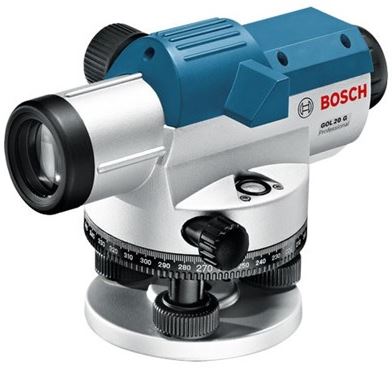
Product Features
The numbering of the product features shown refers to the illustration of the measuring tool on the graphic page.
- Objective lens
- Optical peep sight
- Bubble vial mirror
- Eyepiece cover
- Adjusting screw for sighting line
- Eyepiece
- Circular bubble vial
- Compensator lock
- Horizontal circle reference mark
- Horizontal circle
- Adjusting screw of circular bubble vial
- Levelling screw
- Tripod mount 5/8″ (on the rear side)
- Horizontal drive screw
- Serial number
- Focusing knob
- Allen key
- Adjusting pin
- Case
- Plumb-bob
The accessories illustrated or described are not included as standard delivery.
Technical Data

Operation
- Check the levelling and indication accuracy of the measuring tool each time before using and after longer transport of the measuring tool.
- Protect the measuring tool against moisture and direct sun light.
- Do not subject the measuring tool to extreme temperatures or variations in temperature.
As an example, do not leave it in vehicles for longer periods. In case of large variations in temperature, allow the measuring tool to adjust to the ambient temperature before putting it into operation. In case of extreme temperatures or variations in temperature, the accuracy of the measuring tool can be impaired. - Avoid any impact to or dropping of the measuring tool. After severe exterior effects to the measuring tool, it is recommended to carry out an accuracy check (see “Accuracy
Check of the Measuring Tool”, page 13) each time before continuing to work. - Place the measuring tool in the provided case when transporting it over larger distances (e.g. in the car). Ensure that themeasuring tool is correctly placed in the transport case. When placing the measuring tool in the case, the compensator is locked; otherwise, it could be damaged in case of intense movement.
Setting Up/Aligning the Measuring Tool
Mounting on the Tripod
Set up the tripod stable and safe against tipping over or slipping off. Place the measuring tool via the tripod mount 13 onto the male thread of the tripod and screw the measuring tool tight with the locking screw of the tripod. Roughly level the tripod.
Over short distances, the measuring tool can be carried mounted on the tripod. To ensure that the measuring tool is not damaged during this,the tripod must be held vertically during transport, and should not be carried lengthwise over the shoulder.
Aligning the Measuring Tool
Align the measuring tool with the levelling screws 12 so that the air bubble is positioned inthe centre of the circular bubble vial 7.

Turn the first two levelling screws A and B to move the air bubble so that it is centred between the two leveling screws. Then turn the third leveling screw C until the air bubble is positioned in the centre of the circular bubble vial.
Any remaining deviation of the measuring tool to the horizontal plane following the balancing of the circular bubble vial is compensated by means of the compensator.
While working, regularly check (e.g. by viewing through the bubble vial mirror 3) whether the air bubble is still in the centre of the circular bubble vial.
Centring the Measuring Tool over a Point on the Ground
If required, centre the measuring tool over a point on the ground. For this, hang the plumbbob 20 onto the locking screw of the tripod.
Align the measuring tool above the point on the ground either by moving the measuring tool on the tripod or by adjusting the tripod.
Focusing the Telescope
Remove the lens cap from the objective lens 1.
Direct the telescope against a bright object or hold a white sheet of paper in front of the objective lens 1. Turn the eyepiece 6 until the crosshair appears sharp and deep black.
Direct the telescope towards the levelling rod, if required with help of the optical peep sight 2.
Turn the focusing knob 16 until the graduation field of the levelling rod appears sharp. Align the crosshair exactly with the centre of the levelling rod by turning the horizontal drive screw 14.

When the telescope is correctly focussed, the crosshair and the image of the levelling rod must remain aligned when moving your eye behind the eyepiece.
Measuring Functions
Always set up the levelling rod exactly vertical.
Direct the aligned and focussed measuring tool against the levelling rod in such a manner that the crosshair faces centrally against the levelling rod.
Reading Off the Height
Read off the height of the levelling rod at the centre line of the crosshair.
Height measured in the figure:
1.195 m.

Measuring a Distance
Centre the measuring tool above the point from which on the distance is to be measured.
Read off the height of the levelling rod at the top and bottom stadia lines. Multiply the difference of both heights by 100 to receive the distance from the measuring tool to the levelling rod.
Distance measured in the figure:
(1.347 m – 1.042 m) x 100 = 30.5 m.

Measuring Angles
Centre the measuring tool above the point from which on the angle is to be measured.

Direct the measuring tool against point A. Rotate the horizontal circle 10 with the zero point toward the reference mark 9. Then direct the measuring tool against point B. Read off the angle at the reference mark 9.
GOL 20 D/GOL 26 D: Angle measured in the example:
45°.
GOL 20 G/GOL 26 G: Angle measured in the example:
45 gon.
Accuracy Check of the Measuring Tool
Check the levelling and indication accuracy of the measuring tool each time before using and after longer transport of the measuring tool.
Checking the Circular Bubble Vial
Align the measuring tool with the levelling screws 12 so that the air bubble is positioned in the centre of the circular bubble vial 7.
Rotate the telescope by 180°. When the air bubble is no longer in the centre of the circular bubble vial 7, the circular bubble vial must be readjusted.
Readjusting the Circular Bubble Vial
Bring the air bubble of the circular bubble vial 7 in a position between the centre and the end position of the check by turning the levelling screws 12.


Using the Allen key 17, turn the adjusting screws 11 until the air bubble is positioned in the centre of the circular bubble vial.
Check the circular bubble vial by rotating the telescope by 180°. If required, repeat the procedure or refer to an authorised Bosch after-sales service.
Checking the Compensator
After aligning and focussing the measuring tool, measure the height at a reference point. Then press the lock button of the compensator 8 and release again. Measure the height again at the reference point.
If both heights do not exactly match, have the measuring tool repaired by an authorised Bosch after-sales service.
Checking the Crosshair
A measuring distance of approx. 30 m is required for the check. Set up the measuring tool in the centre and levelling rods A and B at both ends of the measuring distance.

After aligning and focussing the measuring tool, read the heights at both levelling rods. Calculate the difference d between the height a1 of levelling rod A and the height b1 of levelling rod B.
Example:
a1 = 1.937 m
b1 = 1.689 m
a1 – b1 = 1.937 m – 1.689 m = 0.248 m = d

Set up the measuring tool approx. 1 m away from levelling rod A. After aligning and focussing the measuring tool, read the height a2 at levelling rod A.
Subtract the previously calculated value d from the measured height a2 in order to receive the set value for the height b2 at levelling rod B.
Measure height b2 at levelling rod B. When the measured value deviates by more than 6 mm (GOL 20 D/G) or 3 mm (GOL 26 D/G) from the calculated set value, the crosshair must be readjusted.
Example:
a2 = 1.724 m
d = 0.248 m
a2 – d = 1.724 m – 0.248 m = 1.476 m
GOL 20 D/G: When measuring, height b2 must be 1.476 m ±6 mm.
GOL 26 D/G: When measuring, height b2 must be 1.476 m ±3 mm.
Readjusting the Crosshair

Unscrew the eyepiece cover 4. Using the adjusting pin 18, turn adjusting screw 5 clockwise or anticlockwise until the calculated set value for height b2 is reached when measuring on levelling rod B.
Screw on eyepiece cover 4 again.
Example:
When measuring b2, the value 1.476 m must be set.
Check the crosshair again. If required, repeat the procedure or refer to an authorised Bosch after-sales service.
Maintenance and Service
Maintenance and Cleaning
Store and transport the measuring tool only in the supplied case.
Keep the measuring tool clean at all times.
Do not immerse the measuring tool in water or other fluids.
Wipe off debris using a moist and soft cloth. Do not use any cleaning agents or solvents.
Handle the lenses with particular attention. Remove dust only with a soft brush. Do not touch the lenses with your fingers.
Before storing, allow the measuring tool and the case to dry completely. A bag of silica gel dryer for the removal of residual moisture is included in the case. Renew the bag of silica gel dryer regularly.
If the measuring tool should fail despite the car taken in manufacturing and testing procedures,repair should be carried out by an authorised after- sales service centre for Bosch power tools.
Do not open the measuring tool yourself.
In all correspondence and spare parts orders, please always include the 10-digit article number given on the type plate of the measuring tool.
For repairs, only send in the measuring tool in the case.
After-sales Service and Customer
Assistance
Our after-sales service responds to your questions concerning maintenance and repair of your product as well as spare parts. Exploded views and information on spare parts can also be found under:
www.bosch-pt.com
Our customer service representatives can answer your questions concerning possible applications and adjustment of products and accessories.
Great Britain
Robert Bosch Ltd. (B.S.C.)
P.O. Box 98
Broadwater Park
North Orbital Road
Denham
Uxbridge
UB 9 5HJ
Tel. Service: +44 (0844) 736 0109
Fax: +44 (0844) 736 0146
E-Mail:
Ireland
Origo Ltd.
Unit 23 Magna Drive
Magna Business Park
City West
Dublin 24
Tel. Service: +353 (01) 4 66 67 00
Fax: +353 (01) 4 66 68 88
Australia, New Zealand and Pacific Islands
Robert Bosch Australia Pty. Ltd.
Power Tools
Locked Bag 66
Clayton South VIC 3169
Customer Contact Center
Inside Australia:
Phone: +61 (01300) 307 044
Fax: +61 (01300) 307 045
Inside New Zealand:
Phone: +64 (0800) 543 353
Fax: +64 (0800) 428 570
Outside AU and NZ:
Phone: +61 (03) 9541 5555
www.bosch.com.au
Republic of South Africa
Customer service
Hotline: +27 (011) 6 51 96 00
Gauteng – BSC Service Centre
35 Roper Street, New Centre
Johannesburg
Tel.: +27 (011) 4 93 93 75
Fax: +27 (011) 4 93 01 26
E-Mail:
KZN – BSC Service Centre
Unit E, Almar Centre
143 Crompton Street
Pinetown
Tel.: +27 (031) 7 01 21 20
Fax: +27 (031) 7 01 24 46
E-Mail:
Western Cape – BSC Service Centre
Democracy Way, Prosperity Park
Milnerton
Tel.: +27 (021) 5 51 25 77
Fax: +27 (021) 5 51 32 23
E-Mail:
Bosch Headquarters
Midrand, Gauteng
Tel.: +27 (011) 6 51 96 00
Fax: +27 (011) 6 51 98 80
E-Mail:
People’s Republic of China
Website: www.bosch-pt.com.cn
China Mainland
Bosch Power Tools (China) Co., Ltd.
567, Bin Kang Road
Bin Jiang District 310052
Hangzhou, P.R.China
Service Hotline: 800 8 20 84 84
Tel.: +86 (571) 87 77 43 38
Fax: +86 (571) 87 77 45 02
HK and Macau Special Administrative Regions
Robert Bosch Hong Kong Co. Ltd.
21st Floor, 625 King’s Road
North Point, Hong Kong
Customer Service Hotline: +852 (21) 02 02 35
Fax: +852 (25) 90 97 62
E-Mail:
www.bosch-pt.com.cn
Indonesia
PT. Multi Tehaka
Kawasan Industri Pulogadung
Jalan Rawa Gelam III No. 2
Jakarta 13930
Indonesia
Tel.: +62 (21) 46 83 25 22
Fax: +62 (21) 46 82 86 45/68 23
E-Mail:
www.multitehaka.co.id
Philippines
Robert Bosch, Inc.
28th Floor Fort Legend Towers,
3rd Avenue corner 31st Street,
Fort Bonifacio Global City,
1634 Taguig City, Philippines
Tel.: +63 (2) 870 3871
Fax: +63 (2) 870 3870
matheus.
www.bosch-pt.com.ph
Bosch Service Center:
9725-27 Kamagong Street
San Antonio Village
Makati City, Philippines
Tel.: +63 (2) 899 9091
Fax: +63 (2) 897 6432
Malaysia
Robert Bosch (S.E.A.) Pte. Ltd.
No. 8A, Jalan 13/6
G.P.O. Box 10818
46200 Petaling Jaya
Selangor, Malaysia
Tel.: +60 (3) 7966 3194
Fax: +60 (3) 7958 3838
Toll-Free: 1800 880 188
www.bosch-pt.com.my
Thailand
Robert Bosch Ltd.
Liberty Square Building
No. 287, 11 Floor
Silom Road, Bangrak
Bangkok 10500
Tel.: +66 (2) 6 31 18 79 – 18 88 (10 lines)
Fax: +66 (2) 2 38 47 83
Robert Bosch Ltd., P. O. Box 2054
Bangkok 10501, Thailand
Bosch Service – Training Centre
2869-2869/1 Soi Ban Kluay
Rama IV Road (near old Paknam Railway)
Prakanong District
10110 Bangkok
Thailand
Tel.: +66 (2) 6 71 78 00 – 4
Fax: +66 (2) 2 49 42 96
Fax: +66 (2) 2 49 52 99
Singapore
Robert Bosch (SEA) Pte. Ltd.
11 Bishan Street 21
Singapore 573943
Tel.: +65 6571 2772
Fax: +65 6350 5315
Toll-Free: 1800 333 8333
www.bosch-pt.com.sg
Vietnam
Robert Bosch Vietnam Co. Ltd
10/F, 194 Golden Building
473 Dien Bien Phu Street
Ward 25, Binh Thanh District
84 Ho Chi Minh City
Vietnam
Tel.: +84 (8) 6258 3690 ext. 413
Fax: +84 (8) 6258 3692
www.bosch-pt.com
Disposal
Measuring tools, accessories and packaging should be sorted for environmental-friendly recycling.
Subject to change without notice.