Bosch GSB 1600 RE Professional Impact Drill Machine Instruction Manual


GSB 1600 RE Professional
Original instructions


Products sold in GB only: Your product is fitted with a BS 1363/A approved electric plug with an internal fuse (ASTA approved to BS 1362).
If the plug is not suitable for your socket outlets, it should be cut off and an appropriate plug fitted in its place by an authorized customer service agent. The replacement plug should have the same fuse rating as the original plug.
The severed plug must be disposed of to avoid a possible shock hazard and should never be inserted into the main socket elsewhere.
Products sold in AUS and NZ only: Use a residual current device (RCD) with a rated residual current of 30 mA or less.
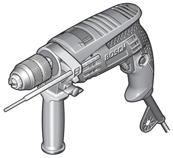
Product Description and Specifications
While reading the operating instructions, unfold the graphics page for the machine and leave it open.

Intended Use
The machine is intended for impact drilling in brick, concrete, and stone as well as for drilling in wood, metal, and plastic. Machines with electronic control and right/left rotation are also suitable for screwdriving and thread-cutting.
Product Features
The numbering of the product features refers to the illustration of the machine on the graphics page.
- Keyless chuck
- Front sleeve
- Rear sleeve
- “Drilling/Impact Drilling” selector switch
- Handle (insulated gripping surface)
- Lock-on button for On/Off switch
- On/Off switch
- Thumbwheel for speed preselection
- Rotational direction switch
- Button for depth stop adjustment
- Wing bolt for adjustment of the auxiliary handle
- Auxiliary handle (insulated gripping surface)*
- Depth stop*
- Universal bit holder*
- Screwdriver bit*
- Allen Key**
- Open-end spanner**
*Accessories shown or described are not part of the standard delivery scope of the product. A complete overview of accessories can be found in our accessories program.
**Commercially available (not included in the delivery scope)
Technical Data
| Impact Drill | GSB 1600 RE Professional | |
| Article number | 3 601 B18 1.. | |
| Rated power input | W | 701 |
| Output power | W | 351 |
| No-load speed | min-¹ | 0–3000 |
| Rated speed | min-¹ | 1640 |
| Impact rate | min-¹ | 26270 |
| Rated torque | Nm | 2 |
| Speed preselection | ||
| Right/left rotation | 43 | |
| Spindle collar dia. | mm | |
| Max. drilling dia. | ||
| – Brickwork | mm | 18 |
| – Concrete | mm | 16 |
| – Steel | mm | 12 |
| – Wood | mm | 30 |
| Chuck clamping range | mm | 1.5–13 |
| Weight according to EPTA-Procedure 01/2003 |
kg | 1.9 |
| Protection class | ||

The values given are valid for a nominal voltage [U] of 230 V. For different voltages and models for specific countries, these values can vary. Please observe the article number on the type plate of your machine. The trade names of the individual machines may vary.
Noise/Vibration Information
Measured sound values were determined according to EN 60745.
Typically the A-weighted noise levels of the product are:
Sound pressure level 98 dB(A); Sound power level
109 dB(A). Uncertainty K =3 dB.
Wear hearing protection!
Vibration total values ah (triax vector sum) and uncertainty K determined according to EN 60745:
Drilling into metal: ah =2.7 m/s², K=1.5 m/s²,
Impact drilling into concrete: ah =23m/s², K=3.5 m/s²,
Screwdriving without impact: ah <2.5m/s², K=1.5 m/s²,
Tapping: ah <2.5 m/s², K=1.5 m/s².
The vibration emission level given in this information sheet has been measured in accordance with a standardized test given in EN 60745 and may be used to compare one tool with another. It may be used for a preliminary assessment of exposure.
The declared vibration emission level represents the main applications of the tool. However, if the tool is used for different applications, with different accessories, or poorly maintained, the vibration emission may differ. This may significantly increase the exposure level over the total working period. An estimation of the level of exposure to vibration should also take into account the times when the tool is switched off or when it is running but not actually doing the job. This may significantly reduce the exposure level over the total working period. Identify additional safety measures to protect the operator from the effects of vibration such as: maintaining the tool and the accessories, keeping the hands warm, and organization of work patterns.
Declaration of Conformity

We declare under our sole responsibility that the product described under “Technical Data” is in conformity with the following standards or standardization documents: EN 60745 according to the provisions of the directives 2004/108/EC, 2006/42/EC.
Technical file at:
Robert Bosch GmbH, PT/ESC,
D-70745 Leinfelden-Echterdingen
| Dr. Egbert Schneider Senior Vice President Engineering |
Dr. Eckerhard Strötgen Head of Product Certification |


Robert Bosch GmbH, Power Tools Division
D-70745 Leinfelden-Echterdingen
Leinfelden, 09.06.2011
Assembly
Auxiliary Handle (see figure A)
Operate your machine only with the auxiliary handle 12.
The auxiliary handle 12 can be set to any position for a secure and low-fatigue working posture.
Turn the wing bolt for adjustment of the auxiliary handle 11 in an anticlockwise direction and set the auxiliary handle 12 to the required position. Then tighten the wing bolt 11 again in a clockwise direction.
Adjusting the Drilling Depth (see figure A)
The required drilling depth X can be set with depth stop 13.
Press the button for the depth stop adjustment 10 and insert the depth stop into the auxiliary handle 12.
Pull out the depth stop until the distance between the tip of the drill bit and the tip of the depth stop correspond with the desired drilling depth X
Changing the Tool
▶ Before any work on the machine itself, pull the mains plug.
Keyless Chuck (see figure B)
Hold the rear sleeve 3 of the keyless chuck 1 tight and turn the front sleeve 2 in a rotation direction until the tool can be inserted. Insert the tool.
Hold the rear sleeve 3 of the keyless chuck 1 tight and firmly turn the front sleeve 2 in the rotation direction 2 by hand until the locking action is no longer heard.
This automatically locks the drill chuck. The locking is released again to remove the tool when the front sleeve 2 is turned in the opposite direction.
Screwdriver Tools (see figure C)
When working with screwdriver bits 15, a universal bit holder
14 should always be used. Use only screwdriver bits that fit the screw head.
For driving screws, always position the “Drilling/Impact Drilling” selector switch 4 to the “Drilling” symbol.
Replacing the Drill Chuck
Before any work on the machine itself, pull the mains plug.
Removing the Drill Chuck (see figure F)
To remove the keyless chuck 1, clamp an Allen key 16 into the keyless chuck 1 and position the open-end wrench 17 (size 12) against the spanner flats of the drive spindle. Place the machine on a firm surface, e.g. a workbench. Hold the open-end wrench 17 firmly and loosen the keyless chuck 1 by turning the Allen key 16 in an anticlockwise direction. A tightly sitting keyless chuck is loosened with a light blow onto the long end of the Allen key 16. Remove the Allen key from the keyless chuck and completely unscrew it from the machine.
Mounting the Drill Chuck (see figure G)
The keyless chuck is mounted in reverse order.

Operation
Starting Operation
▶ Observe correct mains voltage! The voltage of the power source must agree with the voltage specified on the nameplate of the machine. Power tools marked with 230 V can also be operated with 220 V.
Reversing the Rotational Direction (see figures D–E)
The rotational direction switch 9 is used to reverse the rotational direction of the machine. However, this is not possible with the On/Off switch 7 actuated.
Right Rotation: For drilling and driving in screws, push the rotational direction switch 9 left to the stop.
Left Rotation: For loosening and unscrewing screws and nuts, press the rotational direction switch 9 through to the right stop.
Setting the Operating Mode
Set the selector switch 4 to the “Drilling” symbol.
Set the selector switch 4 to the “Impact drilling” symbol.
The selector switch 4 engages noticeably and can also be actuated with the machine running.


Switching On and Off
To start the machine, press the On/Off switch 7 and keep it pressed.
To lock the pressed On/Off switch 7, press the lock-on button 6.
To switch off the machine, release the On/Off switch 7, or when it is locked with the lock-on button 6, briefly press the On/Off switch 7 and then release it.
Adjusting the Speed/Impact Frequency
The speed/impact rate of the switched-on power tool can be variably adjusted, depending on how far the On/Off switch 7 is pressed. Light pressure on the On/Off switches 7 results in a low speed/impact rate.
Further pressure on the witch increases the speed/impact rate.
Preselecting the Speed/Impact Frequency
With the thumbwheel for speed preselection 8, the required speed/impact frequency can be preselected even during operation.
The required speed/impact frequency depends on the material and the working conditions and can be determined through practical testing.
Working Advice
Before any work on the machine itself, pull the mains plug.
Apply the power tool to the screw/nut only when it is switched off. Rotating tool inserts can slip off.
Tips
After longer periods of working at low speed, allow the machine to cool down by running it for approx. 3 minutes at maximum speed with no load.
For drilling in tiles, set the selector switch 4 to the “Drilling” symbol. Do not switch over to the symbol “Impact Drilling” or work with the impact until after drilling through the tile.
Use carbide-tipped drill bits when working in concrete, masonry, and brick wall.
For drilling in metal, use only perfectly sharpened HSS drill bits (HSS=high-speed steel). The appropriate quality is guaranteed by the Bosch accessories program.
Twist drills from 2.5–10 mm can easily be sharpened with the drill bit sharpener (see accessories).
Maintenance and Service
Maintenance and Cleaning
▶ Before any work on the machine itself, pull the mains plug.
▶ For safe and proper working, always keep the machine and ventilation slots clean.
If the machine should fail despite the care taken in manufacturing and testing procedures, repair should be carried out by an after-sales service center for Bosch power tools.
In all correspondence and spare parts orders, please always include the 10-digit article number given on the type plate of the machine.
After-sales Service and Customer Assistance
Our after-sales service responds to your questions concerning maintenance and repair of your product as well as spare parts. Exploded views and information on spare parts can also be found under: www.bosch-pt.com Our customer service representatives can answer your questions concerning possible applications and adjustments of products and accessories.
Great Britain
Robert Bosch Ltd. (B.S.C.)
P.O. Box 98
Broadwater Park
North Orbital Road
Denham
Uxbridge
UB 9 5HJ
Tel. Service: +44 (0844) 736 0109
Fax: +44 (0844) 736 0146
E-Mail:
Ireland
Origo Ltd.
Unit 23 Magna Drive
Magna Business Park
City West
Dublin 24
Tel. Service: +353 (01) 4 66 67 00
Fax: +353 (01) 4 66 68 88
Australia, New Zealand, and Pacific Islands
Robert Bosch Australia Pty. Ltd.
Power Tools
Locked Bag 66
Clayton South VIC 3169
Customer Contact Center
Inside Australia:
Phone: +61 (01300) 307 044
Fax: +61 (01300) 307 045
Inside New Zealand:
Phone: +64 (0800) 543 353
Fax: +64 (0800) 428 570
Outside AU and NZ:
Phone: +61 (03) 9541 5555
www.bosch.com.au
Republic of South Africa
Customer service
Hotline: +27 (011) 6 51 96 00
Gauteng – BSC Service Centre
35 Roper Street, New Centre
Johannesburg
Tel.: +27 (011) 4 93 93 75
Fax: +27 (011) 4 93 01 26
E-Mail:
Robert Bosch GmbH
Power Tools Division
70745 Leinfelden-Echterdingen
Germany
www.bosch-pt.com
1 609 929 M07 (2011.06) PS / 65 WEU
