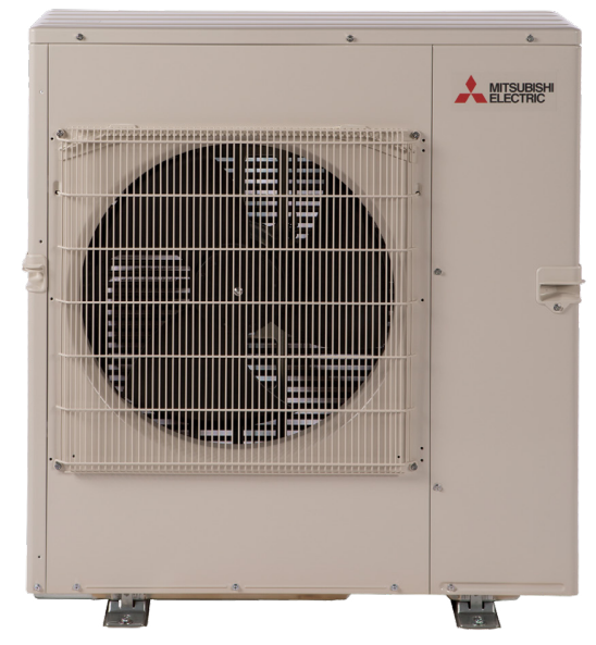
Mitsubishi Electric MXZ-5C42NA3 3.5 Ton Multi Zone Inverter Heat Pump System User Guide

ELECTRIC MXZ-5C42NA3 3.5 Ton Multi-Zone Inverter Heat Pump System
User Guide
MXZ-5C42NA3
3.5-TON MULTI-ZONE INVERTER HEAT-PUMP SYSTEM
Job Name: System Reference:
Date:
FEATURES
- Variable speed INVERTER-driven compressor
- Optional base pan heater
- Quiet outdoor unit operation as low as 56 dB(A)
- High-pressure protection
- Compressor thermal protection
- Compressor overcurrent detection
- Fan motor overheating/voltage protection
SPECIFICATIONS: MXZ-5C42NA3
| Cooling1 (Non-Ducted // Mix // Ducted) | Maximum Capacity | BTU/H | 43,000 // 43,000 // 43,000 |
| Rated Capacity | BTU/H | 40,500 // 39,000 // 37,500 | |
| Minimum Capacity | BTU/H | 12,600 // 12,600 // 12,600 | |
| Maximum Power Input | W | 4,775 // 4,775 // 4,775 | |
| Rated Power Input | W | 4,403 // 4,286 // 4,112 | |
| Power Factor (208V, 230V) | % | 98.9, 98.9 // 98.9, 98.9 // 98.9, 98.9 | |
| Heating at 47°F2 (Non-Ducted // Mix // Ducted) | Maximum Capacity | BTU/H | 53,600 // 53,600 // 53,600 |
| Rated Capacity | BTU/H | 45,000 // 43,000 // 41,000 | |
| Minimum Capacity | BTU/H | 11,400 // 11,400 // 11,400 | |
| Maximum Power Input | W | 6,160 // 6,160 // 6,160 | |
| Rated Power Input | W | 3,575 // 3,519 // 3,463 | |
| Power Factor (208V, 230V) | % | 98.1, 98.1 // 98.2, 98.2 // 98.2, 98.2 | |
| Heating at 17°F3 (Non-Ducted // Mix // Ducted) | Maximum Capacity | BTU/H | 30,500 // 29,800 // 29,100 |
| Rated Capacity | BTU/H | 24,400 // 23,700 // 23,000 | |
| Maximum Power Input | W | 4,750 // 4,991 // 5,231 | |
| Rated Power Input | W | 2,943 // 2,906 // 2,869 | |
| Heating at 5°F4 (Non-Ducted // Mix // Ducted) | Maximum Capacity | BTU/H | 25,000 // 25,000 // 25,000 |
| Maximum Power Input | W | 5,000 // 5,200 // 5,400 | |
| Efficiency (Non-Ducted // Mix // Ducted) | SEER | 19.7 // 17.4 // 15.2 | |
| EER1 | 9.2 // 9.1 // 9.0 | ||
| HSPF (IV) | 10.3 // 9.7 // 9.1 | ||
| COP at 47°F2 | 3.69 // 3.58 // 3.47 | ||
| COP at 17°F at Maximum Capacity3 | 1.88 // 1.75 // 1.63 | ||
| COP at 5°F at Maximum Capacity4 | 1.47 // 1.42 // 1.36 | ||
| ENERGY STAR® Certified | No // No // No | ||
| Electrical | Electrical Power Requirements | Voltage, Phase, Frequency | 208/230, 1, 60 |
| Guaranteed Voltage Range | V AC | 187-253 | |
| Voltage: Indoor – Outdoor, S1-S2 | V AC | 208/230 | |
| Voltage: Indoor – Outdoor, S2-S3 | V DC | 24 | |
| Short-circuit Current Rating (SCCR) | kA | 5 | |
| Recommended Fuse/Breaker Size | A | 40 | |
| Recommended Wire Size | AWG | 14 | |
| Minimum Circuit Ampacity | A | 32.5 | |
| Maximum Overcurrent Protection | A | 40 | |
| Fan Motor Full Load Amperage | A | 2.43 | |
| Outdoor unit | Airflow Rate (Cooling / Heating) | CFM | 2,150 / 2,550 |
| Refrigerant Control | LEV | ||
| Defrost Method | Reverse Cycle | ||
| Heat Exchanger Type | Plate fin coil | ||
| Sound Pressure Level, Cooling1 | dB(A) | 56 | |
| Sound Pressure Level, Heating2 | dB(A) | 58 | |
| Compressor Type | DC INVERTER-driven Twin Rotary | ||
| Compressor Model | MNB33FBTMC-L | ||
| Compressor Rated Load Amps | A | 20 | |
| Compressor Locked Rotor Amps | A | 28.8 | |
| Compressor Oil Type // Charge | oz. | FV50S // 37.2 | |
| Base Pan Heater | Optional | ||
| Unit Dimensions |
W: In. [mm] | 37-13/32 [950] | |
| D: In. [mm] | 13 [330] | ||
| H: In. [mm] | 41-17/64 [1,048] | ||
| Package Dimensions | W: In. [mm] | 41-3/8 [1,050] | |
| D: In. [mm] | 17-3/8 [440] | ||
| H: In. [mm] | 46-3/4 [1,190] | ||
| Unit Weight | Lbs.[kg] | 189 [86] | |
| Package Weight | Lbs.[kg] | 214 [97] | |
| Outdoor unit operating temperature range |
Cooling Intake Air Temp (Maximum / Minimum*A) | °FDB | 115 / 14 |
| Cooling Thermal Lock-out / Re-start Temperatures | °FDB | 10.4 / 14 | |
| Heating Intake Air Temp (Maximum / Minimum) | °FWB | 65 / 5 | |
| Heating Thermal Lock-out / Re-start Temperatures | °FDB | 1.4 / 5 | |
| Refrigerant | Charge | Lbs, oz | 8.0, 13.0 |
| Chargeless Piping Length | Ft. [m] | 98.0 [30.0] | |
| Additional Refrigerant Charge Per Additional Piping Length | oz./Ft. [g/m] | 0.216 [20] | |
NOTES:
AHRI Rated Conditions
(Rated data is determined at a fixed compressor speed)
1 Cooling (Indoor // Outdoor)…………°F 80 DB, 67 WB // 95 DB, 75 WB
2 Heating at 47°F (Indoor // Outdoor)………………°F 70 DB, 60 WB // 47 DB, 43 WB
3 Heating at 17°F (Indoor // Outdoor)…………..°F 70 DB, 60 WB // 17 DB, 15 WB
Conditions
4Heating at 5°F (Indoor // Outdoor)……….. °F 70 DB, 60 WB // 5 DB, 4 WB
*Applications should be restricted to comfort cooling only; equipment cooling applications are not recommended for low ambient temperature conditions. *A 5°F DB – 115°F DB when optional wind baffles are installed
For actual capacity performance based on indoor unit type and the number of indoor units connected, please refer to MXZ Operational Performance. Although the maximum connectable capacity is 130%, the outdoor unit cannot provide more than 100% of the rated capacity. Please utilize this over capacity capability for load shedding or applications where it is known that all connected units will NOT be operating at the same time.
SPECIFICATIONS: MXZ-5C42NA3
|
Indoor unit connection |
Maximum Number of Connected IDU | 5 | |
| Minimum Number of Connected IDU | 2 | ||
| Minimum connected capacity | BTU/H | 12,000 | |
| Maximum connected capacity | BTU/H | 51,000 | |
|
Piping |
Liquid Pipe Size O.D. (Flared) | In.[mm] | A,B,C,D,E: 1/4 [A,B,C,D,E: 6.35] |
| Gas Pipe Size O.D. (Flared) | In.[mm] | A: 1/2; B,C,D,E: 3/8 [A: 12.72; B,C,D,E: 9.52] | |
| Total Piping Length | Ft. [m] | 262 [80] | |
| Maximum Height Difference, ODU above IDU | Ft. [m] | 49 [15] | |
| Maximum Height Difference, ODU below IDU | Ft. [m] | 49 [15] | |
| Farthest Piping Length from ODU to IDU | Ft. [m] | 82 [25] | |
| Maximum Number of Bends for IDU | 80 | ||
NOTES:
AHRI Rated Conditions
(Rated data is determined at a fixed compressor speed)
1Cooling (Indoor // Outdoor)…………………..°F 80 DB, 67 WB // 95 DB, 75 WB
2Heating at 47°F (Indoor // Outdoor)……………………..°F 70 DB, 60 WB // 47 DB, 43 WB
3Heating at 17°F (Indoor // Outdoor)……..°F 70 DB, 60 WB // 17 DB, 15 WB
Conditions
4Heating at 5°F (Indoor // Outdoor)………….. °F 70 DB, 60 WB // 5 DB, 4 WB
*Applications should be restricted to comfort cooling only; equipment cooling applications are not recommended for low ambient temperature conditions. *A 5°F DB – 115°F DB when optional wind baffles are installed
For actual capacity performance based on indoor unit type and a number of indoor units connected, please refer to MXZ Operational Performance. Although the maximum connectable capacity is 130%, the outdoor unit cannot provide more than 100% of the rated capacity. Please utilize this over capacity capability for load shedding or applications where it is known that all connected units will NOT be operating at the same time.
OUTDOOR UNIT ACCESSORIES: MXZ-5C42NA3
| Air Outlet Guide | Air Outlet Guide (1 Piece) | □ PAC-SH96SG-E |
| Ball Valve | Refrigeration Ball Valve – 1/2” | □ BV12FFSI2 |
| Refrigeration Ball Valve – 1/4” | □ BV14FFSI2 | |
| Refrigeration Ball Valve – 3/8” | □ BV38FFSI2 | |
| Refrigeration Ball Valve – 5/8” | □ BV58FFSI2 | |
| Control Wire | M-Net Control Wire, 1,000’ Roll (16-AWG, Standard, Twisted Pair, Shielded, Jacketed- Plenum-rated) | □CW162S-1000 |
| M-Net Control Wire, 250’ Roll (16-AWG, Standard, Twisted Pair, Shielded, Jacketed- Plenum-rated) | □CW162S-250 | |
| Drain Socket | Drain Socket | □ PAC-SG60DS-E |
| Hail Guards | Hail Guard | □ HG-A1 |
| M-NET Converter | M-NET Converter | □ PAC-IF01MNT-E |
| Mini-Split Wire | 14 Gauge, 4 wire MiniSplit Cable—250 ft. roll | □ S144-250 |
| 14 Gauge, 4 wire MiniSplit Cable—250 ft. roll | □ SW144-250 | |
| 14 Gauge, 4 wire MiniSplit Cable—50 ft. roll | □ S144-50 | |
| 14 Gauge, 4 wire MiniSplit Cable—50 ft. roll | □ SW144-50 | |
| 16 Gauge, 4 wire MiniSplit Cable—250 ft. roll | □ S164-250 | |
| 16 Gauge, 4 wire MiniSplit Cable—250 ft. roll | □ SW164-250 | |
| 16 Gauge, 4 wire MiniSplit Cable—50 ft. roll | □ S164-50 | |
| 16 Gauge, 4 wire MiniSplit Cable—50 ft. roll | □ SW164-50 | |
| Mounting Pad | Condensing Unit Mounting Pad: 16” x 36” x 3” | □ ULTRILITE1 |
| Outdoor Unit 3-1/4 inch Mounting Base (Pair) – Plastic | □ DSD-400P | |
| Optional Defrost Heater | Optional Defrost Heater | □ PAC-645BH-E |
| Port Adapter | Adaptor: 1/2” x 3/8” | □ MAC-A455JP-E |
| Adaptor: 1/2” x 5/8” | □ MAC-A456JP-E | |
| Adaptor: 3/8” x 1/2” | □ MAC-A454JP-E | |
| Adaptor: 3/8” x 5/8” | □ PAC-SG76RJ-E | |
| Stand | 18” Single Fan Stand | □ QSMS1801M |
| 24” Single Fan Stand | □ QSMS2401M | |
| Condenser Wall Bracket | □ QSWB2000M-1 | |
| Condenser Wall Bracket – Stainless Steel Finish | □ QSWBSS | |
| Outdoor Unit Stand — 12” High | □ QSMS1201M |
OUTDOOR UNIT DIMENSIONS: MXZ-5C42NA3
Unit: inch (mm)
FORM# MXZ-5C42NA3 – 202206
Specifications are subject to change without notice.
1340 Satellite Boulevard Suwanee, GA 30024
Toll-Free: 800-433-4822
www.mehvac.com
All rights reserved.