Makita DFR452 Cordless Auto Feed Screwdriver Instruction Manual


Makita DFR452 Cordless Auto-Feed Screwdriver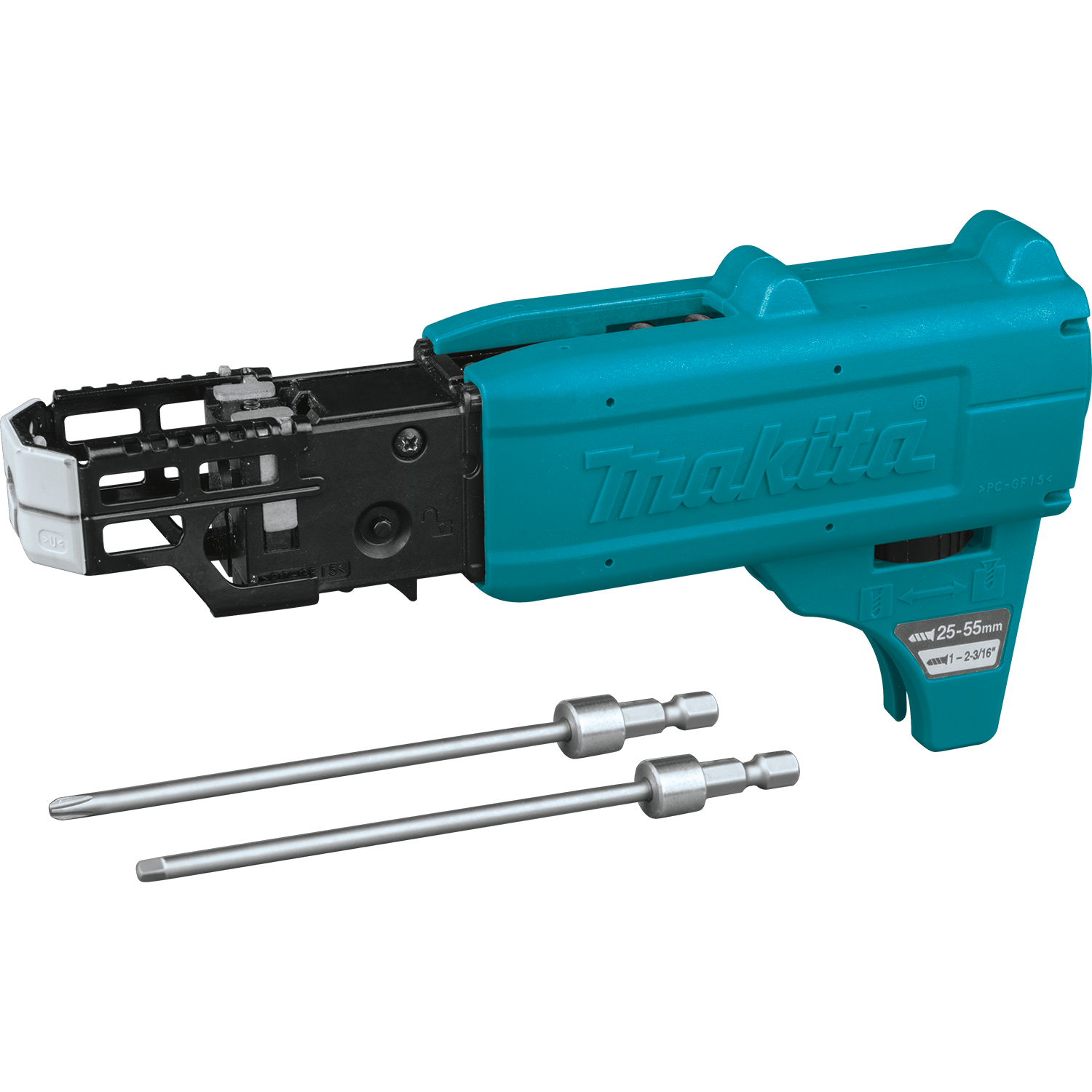

| Model: | DFR452 | DFR551 |
| Screw strip | ø3.5 mm x 20 mm – ø4.2 mm x 41 mm | ø3.5 mm x 25 mm – ø4.2 mm x 55 mm |
| No-load speed (RPM) | 0 – 6,000 min-1 | |
| Overall length | 360 mm | 396 mm |
| Rated voltage | D.C. 18 V | |
| Net weight | 1.9 – 2.2 kg | |
- Due to our continuing program of research and development, the specifications herein are subject to change without notice.
- Specifications may differ from country to country.
- The weight may differ depending on the attachment(s), including the battery cartridge. The lightest and heaviest combinations, according to EPTA-Procedure 01/2014, are shown in the table.
Applicable battery cartridge and charger
- Battery cartridge: BL1815N / BL1820B / BL1830B / BL1840B / BL1850B / BL1860B
- Charger: DC18RC / DC18RD / DC18RE / DC18SD / DC18SE / DC18SF / DC18SH
- Some of the battery cartridges and chargers listed above may not be available depending on your region of residence.
WARNING: Only use the battery cartridges and chargers listed above. Use of any other battery cartridges and chargers may cause injury and/or fire.
Symbols
The followings show the symbols which may be used for the equipment. Be sure that you understand their meaning before use. Read the instruction manual. Only EU countries
Due to the presence of hazardous components in the equipment, waste electrical and electronic equipment, accumulators and batteries may have a negative impact on the environment and human health. Do not dispose of electrical and electronic appliances or batteries with household waste! In accordance with the European Directive on waste electrical and electronic equipment and on accumulators and batteries and waste accumulators and batteries, as well as their adaptation to national law, waste electrical equipment, batteries, and accumulators should be stored separately and delivered to a separate collection point for municipal waste, operating in accordance with the regulations on environmental protection. This is indicated by the symbol of the crossed-out wheeled bin placed on the equipment.
Intended use
The tool is intended for screw driving in wood, metal, and plastic.
Noise
- The typical A-weighted noise level was determined according to EN62841-2-2: Model DFR452
Sound pressure level (LpA): 75 dB(A)
Uncertainty (K): 3 dB(A) Model DFR551
Sound pressure level (LpA): 74 dB(A)
Uncertainty (K): 3 dB(A) - The noise level under working may exceed 80 dB (A).
NOTE
- The declared noise emission value(s) has been measured in accordance with a standard test method and may be used for comparing one tool with another.
- The declared noise emission value(s) may also be used in a preliminary assessment of exposure.
WARNING
- Wear ear protection.
- The noise emission during actual use of the power tool can differ from the declared value(s) depending on the ways in which the tool is used especially what kind of workpiece is processed.
- Be sure to identify safety measures to protect the operator that is based on an estimation of exposure in the actual conditions of use (taking account of all parts of the operating cycle such as the times when the tool is switched off and when it is running idle in addition to the trigger time).
Vibration
- The vibration total value (tri-axial vector sum) determined according to EN62841-2-2: Model DFR452
- Work mode: screwdriving without impact Vibration emission (ah) : 2.5 m/s2 or less Uncertainty (K) : 1.5 m/s2 Model DFR551
Work mode: screwdriving without impact Vibration emission (ah) : 2.5 m/s2 or less Uncertainty (K) : 1.5 m/s2
NOTE
- The declared vibration total value(s) has been measured in accordance with a standard test method and may be used for comparing one tool with another.
- The declared vibration total value(s) may also be used in a preliminary assessment of exposure.
WARNING
The vibration emission during actual use of the power tool can differ from the declared value(s) depending on the ways in which the tool is used especially what kind of workpiece is processed. Be sure to identify safety measures to protect the operator that is based on an estimation of exposure in the actual conditions of use (taking account of all parts of the operating cycle such as the times when the tool is switched off and when it is running idle in addition to the trigger time).
EC Declaration of Conformity
For European countries only: The EC declaration of conformity is included as Annex A to this instruction manual.
SAFETY WARNINGS
General power tool safety warnings
WARNING
Read all safety warnings, instructions, illustrations, and specifications provided with this power tool. Failure to follow all instructions listed below may result in electric shock, fire, and/or serious injury.
Save all warnings and instructions for future reference
The term “power tool” in the warnings refers to your mains-operated (corded) power tool or battery-operated (cordless) power tool.
Work area safety
- Keep the work area clean and well-lit. Cluttered or dark areas invite accidents.
- Do not operate power tools in explosive atmospheres, such as in the presence of flammable liquids, gases, or dust. Power tools create sparks that may ignite dust or fumes.
- Keep children and bystanders away while operating a power tool. Distractions can cause you to lose control.
Electrical safety
- Power tool plugs must match the outlet. Never modify the plug in any way. Do not use any adapter plugs with earthed (grounded) power tools. Unmodified plugs and matching outlets will reduce the risk of electric shock.
- Avoid body contact with earthed or grounded surfaces, such as pipes, radiators, ranges, and refrigerators. There is an increased risk of electric shock if your body is earthed or grounded.
- Do not expose power tools to rain or wet conditions. Water entering a power tool will increase the risk of electric shock.
- Do not abuse the cord. Never use the cord for carrying, pulling, or unplugging the power tool. Keep cord away from heat, oil, sharp edges, or moving parts. Damaged or entangled cords increase the risk of electric shock.
- When operating a power tool outdoors, use an extension cord suitable for outdoor use. The use of a cord suitable for outdoor use reduces the risk of electric shock.
- If operating a power tool in a damp location is unavoidable, use a residual current device (RCD) protected supply. The use of an RCD reduces the risk of electric shock.
- Power tools can produce electromagnetic fields (EMF) that are not harmful to the user. However, users of pacemakers and other similar medical devices should contact the maker of their device and/or doctor for advice before operating this power tool.
Personal safety
- Stay alert, watch what you are doing, and use common sense when operating a power tool. Do not use a power tool while you are tired or under the influence of drugs, alcohol, or medication. A moment of inattention while operating power tools may result in serious personal injury.
- Use personal protective equipment. Always wear eye protection. Protective equipment such as a dust mask, non-skid safety shoes, hard hat, or hearing protection used for appropriate conditions will reduce personal injuries.
- Prevent unintentional starting. Ensure the switch is in the off-position before connecting to a power source and/or battery pack, picking up or carrying the tool. Carrying power tools with your finger on the switch or energizing power tools that have the switch on invites accidents.
- Remove any adjusting key or wrench before turning the power tool on. A wrench or a key left attached to a rotating part of the power tool may result in personal injury.
- Do not overreach. Keep proper footing and balance at all times. This enables better control of the power tool in unexpected situations.
- Dress properly. Do not wear loose clothing or jewelry. Keep your hair and clothing away from moving parts. Loose clothes, jewelry or long hair can be caught in moving parts. If devices are provided for the connection of dust extraction and collection facilities, ensure these are connected and properly used.
- The use of dust collection can reduce dust-related hazards
- Do not let familiarity gained from frequent use of tools allow you to become complacent and ignore tool safety principles. A careless action can cause severe injury within a fraction of a second.
- Always wear protective goggles to protect your eyes from injury when using power tools. The goggles must comply with ANSI Z87.1 in the USA, EN 166 in Europe, or AS/NZS 1336 in Australia/New Zealand. In Australia/New Zealand, it is legally required to wear a face shield to protect your face, too.
It is an employer’s responsibility to enforce the use of appropriate safety protective equipment by the tool operators and by other persons in the immediate working area.

Power tool use and care
- Do not force the power tool. Use the correct power tool for your application. The correct power tool will do the job better and safer at the rate at which it was designed.
- Do not use the power tool if the switch does not turn on and off. Any power tool that cannot be controlled with the switch is dangerous and must be repaired.
- Disconnect the plug from the power source and/or remove the battery pack, if detachable, from the power tool before making any adjustments, changing accessories, or storing power tools. Such preventive safety measures reduce the risk of starting the power tool accidentally.
- Store idle power tools out of the reach of children and do not allow persons unfamiliar with the power tool or these instructions to operate the power tool. Power tools are dangerous in the hands of untrained users.
- Maintain power tools and accessories. Check for misalignment or binding of moving parts, breakage of parts and any other condition that may affect the power tool’s operation. If damaged, have the power tool repaired before use. Many accidents are caused by poorly maintained power tools.
- Keep cutting tools sharp and clean. Properly maintained cutting tools with sharp cutting edges are less likely to bind and are easier to control.
- Use the power tool, accessories and tool bits, etc. in accordance with these instructions, taking into account the working conditions and the work to be performed. Use of the power tool for operations different from those intended could result in a hazardous situation.
- Keep handles and grasping surfaces dry, clean, and free from oil and grease. Slippery handles and grasping surfaces do not allow for safe handling and control of the tool in unexpected situations.
- When using the tool, do not wear cloth work gloves which may be entangled. The entanglement of cloth work gloves in the moving parts may result in personal injury.
Battery tool use and care
- Recharge only with the charger specified by the manufacturer. A charger that is suitable for one type of battery pack may create a risk of fire when used with another battery pack.
- Use power tools only with specifically designated battery packs. The use of any other battery packs may create a risk of injury and fire.
- When the battery pack is not in use, keep it away from other metal objects, like paper clips, coins, keys, nails, screws, or other small metal objects, that can make a connection from one terminal to another. Shorting the battery terminals together may cause burns or a fire.
- Under abusive conditions, liquid may be ejected from the battery; avoid contact. If contact accidentally occurs, flush with water. If liquid contacts the eyes, additionally seek medical help. Liquid ejected from the battery may cause irritation or burns.
- Do not use a battery pack or tool that is damaged or modified. Damaged or modified batteries may exhibit unpredictable behavior resulting in fire, explosion, or risk of injury.
- Do not expose a battery pack or tool to fire or excessive temperature. Exposure to fire or temperature above 130 °C may cause an explosion.
- Follow all charging instructions and do not charge the battery pack or tool outside the temperature range specified in the instructions. Charging improperly or at temperatures outside the specified range may damage the battery and increase the risk of fire.
Service
- Have your power tool serviced by a qualified repair person using only identical replacement parts. This will ensure that the safety of the power tool is maintained.
- Never service damaged battery packs. Service of battery packs should only be performed by the manufacturer or authorized service providers.
- Follow instructions for lubricating and changing accessories.
Cordless screwdriver safety warnings
- Hold the power tool by insulated gripping surfaces, when performing an operation where the fastener may contact hidden wiring. Fasteners contacting a “live” wire may make exposed metal parts of the power tool “live” and could give the operator an electric shock.
- Always be sure you have a firm footing. Be sure no one is below when using the tool in high locations.
- Hold the tool firmly.
- Keep hands away from rotating parts.
- Do not touch the bit or the workpiece immediately after operation; they may be extremely hot and could burn your skin.
- Always secure the workpiece in a vise or similar hold-down device.
- Make sure there are no electrical cables, water pipes, gas pipes, etc. that could cause a hazard if damaged by the use of the tool.
SAVE THESE INSTRUCTIONS
WARNING: DO NOT let comfort or familiarity with the product (gained from repeated use) replace strict adherence to safety rules for the subject product. MISUSE or failure to follow the safety rules stated in this instruction manual may cause serious personal injury.
Important safety instructions for battery cartridge
- Before using the battery cartridge, read all instructions and cautionary markings on (1) battery charger, (2) battery, and (3) product using the battery.
- Do not disassemble or tamper with the battery cartridge. It may result in a fire, excessive heat, or explosion.
- If the operating time has become excessively shorter, stop operating immediately. It may result in a risk of overheating, possible burns, and even an explosion.
- If electrolyte gets into your eyes, rinse them out with clear water and seek medical attention right away. It may result in loss of your eyesight.
- Do not short the battery cartridge:
- Do not touch the terminals with any conductive material.
- Avoid storing battery cartridges in a container with other metal objects such as nails, coins, etc.
- Do not expose the battery cartridge to water or rain.
- A battery short can cause a large current flow, overheating, possible burns, and even a breakdown.
- Do not store and use the tool and battery cartridge locations where the temperature may reach or exceed 50 °C (122 °F).
- Do not incinerate the battery cartridge even if it is severely damaged or is completely worn out. The battery cartridge can explode in a fire.
- Do not nail, cut, crush, throw, drop the battery cartridge, or hit against a hard object on the battery cartridge. Such conduct may result in a fire, excessive heat, or explosion.
- Do not use a damaged battery.
- The contained lithium-ion batteries are subject to the Dangerous Goods Legislation requirements. For commercial transports e.g. by third parties or forwarding agents, the special requirements on packaging and labeling must be observed.
- For commercial transport e.g. by third parties, or forwarding agents, the special requirement on packaging and labeling must be observed For the preparation of the item being shipped, consulting an expert for hazardous material is required. Please also observe possibly more detailed national regulations. Tape or mask off open contacts and pack up the battery in such a manner that it cannot move around in the packaging.
- When disposing of the battery cartridge, remove it from the tool and dispose of it in a safe place. Follow your local regulations relating to the disposal of batteries.
- Use the batteries only with the product specified by Makita. Installing the batteries to non-compliant products may result in a fire, excessive heat, explosion, or leak of electrolyte.
- If the tool is not used for a long period of time, the battery must be removed from the tool.
- During and after use, the battery cartridge may take on heat which can cause burns or low-temperature burns. Pay attention to the handling of hot battery cartridges.
- Do not touch the terminal of the tool immediately after use as it may get hot enough to cause burns.
- Do not allow chips, dust, or soil to stuck into the terminals, holes, and grooves of the battery cartridge. It may result in poor performance or breakdown of the tool or battery cartridge.
- Unless the tool supports the use of near high-voltage electrical power lines, do not use the battery cartridge near high-voltage electrical power lines. It may result in a malfunction or breakdown of the tool or battery cartridge.
- Keep the battery away from children.
SAVE THESE INSTRUCTIONS.
CAUTION
Only use genuine Makita batteries. Use of non-genuine Makita batteries, or batteries that have been altered, may result in the battery bursting causing fires, personal injury, and damage. It will also void the Makita warranty for the Makita tool and charger.
Tips for maintaining maximum battery life
- Charge the battery cartridge before completely discharged. Always stop tool operation and charge the battery cartridge when you notice less tool power.
- Never recharge a fully charged battery cartridge. Overcharging shortens the battery service life.
- Charge the battery cartridge at room temperature at 10 °C – 40 °C (50 °F – 104 °F). Let a hot battery cartridge cool down before charging it.
- When not using the battery cartridge, remove it from the tool or the charger.
- Charge the battery cartridge if you do not use it for a long period (more than six months)
FUNCTIONAL DESCRIPTION
CAUTION: Always be sure that the tool is switched off and the battery cartridge is removed before adjusting or checking the function of the tool.
Installing or removing the battery cartridge
- Red indicator
- Button
- Battery cartridge

CAUTION
- Always switch off the tool before installing or removing the battery cartridge.
- Hold the tool and the battery cartridge firmly when installing or removing the battery cartridge.
- Failure to hold the tool and the battery cartridge firmly may cause them to slip off your hands and result in damage to the tool and battery cartridge and a personal injury.
Tool/battery protection system
The tool is equipped with a tool/battery protection system. This system automatically cuts off power to the motor to extend tool and battery life. The tool will automatically stop during operation if the tool or battery is placed under one of the following conditions:
- Overload protection
When the tool/battery is operated in a manner that causes it to draw an abnormally high current, the tool stops automatically. In this situation, turn the tool off and stop the application that caused the tool to become overloaded. Then turn the tool on to restart. - Overheat protection
When the tool/battery is overheated, the tool stops automatically. In this situation, let the tool/battery cool before turning the tool on again. - Over-discharge protection
When the battery capacity is not enough, the tool stops automatically. In this case, remove the battery from the tool and charge the battery.
Alert indicator
The indicator lamp on the push drive mode selector raises an alert with flashing red lights when the tool works in the following operating conditions.
Indicator lamp

| Lamp status | Causes | Remedies |
| Fast flashing (approx. one-third second intervals) | Battery getting low |
Charge the battery at your earliest opportunity. |
| Delayed flashing (approx. second intervals) | Overheated |
Let the tool cool down before turning it on again. |
Indicating the remaining battery capacity
Only for battery cartridges with the indicator

- Indicator lamps
- Check button
Press the check button on the battery cartridge to indicate the remaining battery capacity. The indicator lamps light up for a few seconds.

NOTE
- Depending on the conditions of use and the ambient temperature, the indication may differ slightly from the actual capacity.
- The first (far left) indicator lamp will blink when the battery protection system works.
The setting for desired screw lengths
For model DFR452
The tool provides 4 positive-lock screw length settings. Slide the stopper base out and in while depressing the levers on the top surface of the stopper base so the number for desired screw length (indicated on the label) appears in the reading window. See the following table for details on the numbers allocated to your desired screw lengths.

- Stopper base
- Levers
- Label
- Reading window
| numbers indicated on the label | Screw length ranges |
| 20 | 20 mm (3/4″) |
| 25 | 25 mm – 28 mm (1″ – 1-1/8″) |
| 32 | 28 mm – 35 mm (1-1/8″ – 1-3/8″) |
| 41 | 35 mm – 41 mm (1-3/8″ – 1-5/8″) |
For model DFR551
The tool provides 7 positive-lock screw length settings. Slide the stopper base out and in while depressing the levers on the top surface of the stopper base so the number for desired screw length (indicated on the label) appears in the reading window. See the following table for details on the numbers allocated to your desired screw lengths.

- Stopper base
- Levers
- Label
- Reading window
| NumbersThe numbers indicated on the label | Screw length ranges |
| 25 | 25 mm (1″) |
| 30 | 25 mm – 30 mm (1″ – 1-3/16″) |
| 35 | 30 mm – 35 mm (1-3/16″ – 1-3/8″) |
| 40 | 35 mm – 40 mm (1-3/8″ – 1-9/16″) |
| 45 | 40 mm – 45 mm (1-9/16″ – 1-3/4″) |
| 50 | 45 mm – 50 mm (1-3/4″ – 2″) |
| 55 | 50 mm – 55 mm (2″ – 2-3/16″) |
Adjusting driving depths
Press the front face of the stopper base and hold the feeder box down into the casing as far as it will go. While keeping it in that position, turn the adjusting dial so that the driver bit tip comes out approximately 6 mm from the front face of the stopper base. Drive a trial screw. If the screw head stands above the workpiece surface, turn the adjusting dial in the A direction; if the screw head sits below the surface, turn the adjusting dial in the B direction.

- Approx 6 mm
- Stopper base
- Feeder box
- Casing
- Adjusting dial
Switch action
WARNING: Before installing the battery cartridge into the tool, always check to see that the switch trigger actuates properly and returns to the “OFF” position when released. To start the tool, pull the switch trigger. Tool speed is increased by increasing pressure on the switch trigger. Release the switch trigger to stop. For continuous operation, pull the switch trigger, push the lock button and then release the trigger. To stop the tool from the locked position, pull the switch trigger fully, and then release it.

- Switch trigger
- Lock button
CAUTION
Reversing switch action
- Always check the direction of rotation before operation.
- Use the reversing switch only after the tool comes to a complete stop. Changing the direction of rotation before the tool stops may damage the tool.
- When not operating the tool, always set the reversing switch lever to the neutral position.
This tool has a reversing switch to change the direction of rotation. Depress the reversing switch lever from the A-side for clockwise rotation or from the B-side for counterclockwise rotation. When the reversing switch lever is in the neutral position, the switch trigger cannot be pulled.

- Reversing switch lever
Push drive mode
In push drive mode, the driver bit only rotates by applying pressure onto the driving surface with the stopper base, allowing the tool to cut off power to the motor to save battery power at idle. To select push drive mode, pull the switch trigger slightly, then release it and quickly press the mode select button. The indicator lamp on the push drive mode selector will then light up.

- Mode select button
- Indicator lamp
NOTE: Push drive mode will automatically be deactivated after eight hours with the switch trigger locked on and no further switch operation. To restart the tool, pull the switch trigger fully to release the lock button, and pull the trigger again.
ASSEMBLY
CAUTION: Always be sure that the tool is switched off and the battery cartridge is removed before carrying out any work on the tool.
Removing and installing driver bit
- CAUTION: Be careful not to touch the sharp edges of screws while reassembling the components and attachments.
- CAUTION: Handle accessories and attachments with care. Always be sure to hold accessories and attachments body firmly when install-location and uninstallation to avoid them falling or slipping off from your hands.

- Press and hold the release buttons on each side of the casing, and then pull the casing apart.
- Release buttons
- Casing
- To remove the driver bit, pull it off while pushing and holding the spindle into the gear housing.
- Driver bit
- Spindle
- Gear housing
- To install a driver bit, place it into the spindle hole as far as it will go while pushing and holding the spindle into the gear housing. Then release the spindle to secure the driver bit.
- Reset the casing back onto the gear housing while holding its body firmly until the release buttons on each side of the casing lock in place.

Installing screw strip
Insert a screw strip through the screw strip guide on the casing, and then insert it through the screw loading guide in the feeder box.

- Screw strip
- Screw strip guide
- Casing
- Screw loading guide
- Feeder box
NOTICE: Make sure to set the first screw in the second row next to the driving position.

- First screw
- Driving position
Removing screw strip
To remove the screw strip, pull it upwards out of the feeder box.

The screw strip can be pulled downwards out of the feeder box while pressing the reverse button on the feeder box.

- Reverse button
- Feeder box
Installing hook
CAUTION: When installing the hook, always secure it with the screw firmly. If not, the hook may come off from the tool and result in personal injury.

- Groove
- Hook
- Screw
The hook is convenient for temporarily hanging the tool. This can be installed on either side of the tool. To install the hook, insert it into a groove in the tool housing on either side and then secure it with a screw. To remove, loosen the screw and then take it out.
OPERATION
Driving operation
NOTICE
- Always check the driver bit carefully for wear before driving operations. Replace a worn driver bit or poor fastening may result.
- Always hold the tool squarely against the driving surface. Holding it at an angle may damage the screw heads and cause wear on the driver bit. This may also lead to poor fastening.
- Always keep the tool firmly against the driving surface until the driving is over. Failure to do so may cause insufficient fastening of screws.
- Be careful not to drive a screw onto another screw already fastened.
- Do not operate the tool without screws. It will damage the driving surface.
- If the feeder box does not work smoothly when driving screws, spray car wax (spray type) on the sliding surfaces. Never lubricate it.
Switch on the tool by pulling the switch trigger. Hold the tool squarely and firmly up against the driving surface. A screw will be automatically carried to the driving position and fastened.

Driving operation in push drive mode
- Pull the switch trigger slightly and release it. Then quickly press the mode select button. The indicator lamp on the push drive mode selector lights up, and push drive mode becomes activated.
- Mode select button
- Indicator lamp
- Depress the lock button while pulling the switch trigger, and then release the switch trigger.
- Lock button
- Switch trigger
- NOTE: While selecting push drive mode and locking the trigger on, the motor does not rotate under no load to minimize power consumption.
- Hold the tool squarely against the driving surface and apply forward pressure to the tool. The screw will be automatically carried to the driving position and driven at full speed.


Driving in corner
CAUTION: Driving at a position closer than 15 mm to the wall or driving with the stopper base in contact with the wall may damage the screw heads and cause wear on the driver bit. This may also lead to the poor fastening of screws and malfunction of the tool. This tool can be used to drive at a position 15 mm away from the wall as shown in the figure.

- Wall
- Stopper base
- 15 mm
Unfastening operation
CAUTION
- Always check the direction of rotation before operation.
- Use the reversing switch only after the tool comes to a complete stop. Changing the direction of rotation before the tool stops may damage the tool.
The tool allows you to change the direction of driver bit rotation with ease, either towards the right (clockwise) to tighten a screw or towards the left (counterclockwise) to loosen a screw.
- Depress the reversing switch lever from the B side for counterclockwise rotation.

Press and hold the release buttons on each side of the casing, and then pull the casing apart.

- Release buttons
- Casing
- Place the tip of the driver bit into the head of the screw to be loosened.
- Hold the tool firmly against the screw and squeeze the switch trigger to start.

- Driver bit
- Screw head
- Switch trigger
Reset the casing back onto the gear housing until it locks in place after finishing the operation.
MAINTENANCE
- CAUTION: Always be sure that the tool is switched off and the battery cartridge is removed before attempting to perform inspection or maintenance.
- NOTICE: Never use gasoline, benzene, thinner, alcohol, or the like. Discoloration, deformation, or cracks may result.
To maintain product SAFETY and RELIABILITY, repairs, and any other maintenance or adjustment should be performed by Makita Authorized or Factory Service Centers, always using Makita replacement parts.
After use
Wipe off the tool using a dry cloth or cloth slightly moistened with soapy water at regular intervals.
OPTIONAL ACCESSORIES
CAUTION: These accessories or attachments are recommended for use with your Makita tool specified in this manual. The use of any other accessories or attachments might present a risk of injury to persons. Only use accessory or attachment for its stated purpose. If you need any assistance with more details regarding these accessories, ask your local Makita Service Center.
- Drywall screw strip
- Phillips bit
- Square bit
- Pozidriv bit
- Feeder box
- Casing
- Makita genuine battery and charger
NOTE: Some items in the list may be included in the tool package as standard accessories. They may differ from country to country www.makita.com