LG Digital Signage (MONITOR SIGNAGE) webOS 4.0 User Manual


To obtain the source code that is contained in this product, under GPL, LGPL, MPL, and other open source licenses that have the obligation to disclose source code, and to access all referred license terms, copyright notices and other relevant documents, please visit https://opensource.lge.com.
LG Electronics will also provide open source code to you on CD-ROM for a charge covering the cost of performing such distribution (such as the cost of media, shipping, and handling) upon email request to
This offer is valid to anyone in receipt of this information for a period of three years after our last shipment of this product.
How To Access LG System Controller Page
- Enter https://System Controller’s IP Address:3737 into the address field of the web browser.
- Select Advanced, and select Move to SetIP (unsafe).
- Enter the password into the password field. (Default set value: serial number followed by LGe12#)
For example, the password for serial number ABCD123456789 would be ABCD123456789LGe12#. - Enter CAPTCHA (auto-input prevention).
- When you sign in for the first time, a password change pop-up will appear and you’ll be required to change the password.
- The password should consist of more than 8 characters, including numbers, upper and lowercase alphabets, and special characters. The new password cannot be the same as the old password.


NOTE
If you’re setting up more than one System Controller, configure local networks (router, hub, etc.) that are separate from each other to prevent the same power unit from being registered more than once.
LG System Controller Menu
Menu
Language
You can set the language used for the System Controller. Or you can change the language by using the RS-232C command below. (See the section of “Language” on page 16.)

| No. | Item | Description |
| 1 | Select language window | You can change the language via the select box. |
| 2 | Done | Applies the selected language. |
Network
You can change the network configuration environment of the System Controller. You can access the System Controller page via the set value. (See the section of “Network” on page 17.)

| No. | Item | Description |
| 1 | Select language window | You can change the language via the select box. |
| 2 | Done | Applies the selected language. |
| 6 | DNS Server | You can manually set the address of the Domain Name System (DNS) server. |
| 7 | 802.1X EAP | Authentication based on IEEE 802.1X can be used for wired connections. |
|
8 |
802.1X EAP Settings |
Select the desired EAP type and Phase 2 Authentication, enter the ID/ password registered in the authentication server, and click the ‘Connect’ button to save the connection settings. |
|
9 |
Download Certificate |
This is the function for downloading the certificate and key required for 802.1X EAP authentication. It supports certificates and keys with a pem extension. |
| 10 | Ping Test | It is performed by the two methods: the IP address and URL address methods. It receives/transmits a ping for the input address 10 times, conducts a Ping Test, and outputs the results. |
| 11 | Apply | You can apply the set value via the Apply button. |


LED Assistant
You can connect to the System Controller by changing the configuration environment of the network connected to the LED Assistant page. You can access the LED Assistant page via the set value.

| No. | Item | Description |
| 1 | Activate | You can activate/deactivate via the Activate button. If you deactivate the Activate button, the connection with the server will be lost. |
| 2 | Advanced Options | You can select either IPv4 or IPv6 method for the LED Assistant Server’s IP address. |
| 3 | IP Address | If you select IPv4 method for the LED Assistant Server’s IP address system, you can enter four-digit decimal numbers separated by “.”. If you select IPv6 method for the LED Assistant Server’s IP address system, you can enter eight-digit hexadecimal numbers separated by “:”. |
| 4 | Port Number | You can set it by receiving an input of Port numbers in the decimal number. The default port number is 3001. |
| 5 | Status | Displays the connection status. (When connected: Connected/when not connected: Not Connected) |
| 6 | Apply | You can apply the set value via the [Apply] button. |
Numbers 7 to 9 are only supported by some models.
LED Assistant
| No. | Item | Description |
| 1 | Activate | You can activate/deactivate via the Activate button. If you deactivate the Activate button, the connection with the server will be lost. |
| 2 | Advanced Options | You can select either IPv4 or IPv6 method for the LED Assistant Server’s IP address. |
| 3 | IP Address | If you select IPv4 method for the LED Assistant Server’s IP address system, you can enter four-digit decimal numbers separated by “.”. If you select IPv6 method for the LED Assistant Server’s IP address system, you can enter eight-digit hexadecimal numbers separated by “:”. |
| 4 | Port Number | You can set it by receiving an input of Port numbers in the decimal number. The default port number is 3001. |
| 5 | Status | Displays the connection status. (When connected: Connected/when not connected: Not Connected) |
| 6 | Apply | You can apply the set value via the [Apply] button. |
You can connect to the System Controller by changing the configuration environment of the network connected to the LED Assistant page. You can access the LED Assistant page via the set value.
LG ConnectedCare (Signage 365 Care)
- The following method applies only to some models.
- A pop-up for network settings is displayed.
- Click the [Network Settings] button to be redirected to the network page. – Click the [NO] button to close the pop-up.
NOTE
- The pop-up only appears if the network settings have not been set.

LG ConnectedCare App Not Installed

| No. | Item | Description |
| 1 | Install | Proceeds with the installation of the LG ConnectedCare app. |
LG ConnectedCare App Installed

| No. | Item | Description |
| 1 | LG ConnectedCare App | You can activate/deactivate via the LG ConnectedCare app button. |
| 2 | Account | Displays the account number and name. |
| 3 | Version | Displays the version of the LG ConnectedCare app. |
| 4 | Server Status | Displays the status of the LG ConnectedCare app. There are four states: Waiting for Approval, Connected, Not Connected, and Rejected. |
| 5 | Reset | Deletes the LG ConnectedCare app. |

LG ConnectedCare App Installation Process
- A pop-up for entering the account number is displayed. – Enter the 6-digit account number and click the [OK] button.
- A pop-up that informs the difference between the current time and the time set in the LG ConnectedCare app is displayed.
- Click the [Yes] button to automatically set the current time.
NOTE - The pop-up is displayed only when there is a discrepancy between the current time of Signage and the time set in the LG ConnectedCare app.
- Click the [Yes] button to automatically set the current time.
- A pop-up for confirming the account is displayed.
- Confirm your account number and name.
- Click the [Confirm] button to proceed with the installation of the LG ConnectedCare app.
- A pop-up for the installation progress is displayed.
- For Successful Installation
- A pop-up will indicate that the app was successfully installed. The pop-up will close automatically in 5
- For Failed Installation
- A pop-up will indicate that the app installation has failed. Clicking the [OK] button will close the pop-up.


Enterprise Settings
The following method applies only to some models.
The Enterprise Settings can be applied by entering the company account code.

Enterprise code Application Process

- Press the [Enter] button to display a pop-up, and enter the company account code.
- After the code is entered, the enterprise settings will take effect when the set reboots.
- When Applying Enterprise Code
- If a code has already been entered, it cannot be changed to another code.


System
You can initialize and restart the System Controller. In addition, you can perform S/W Update.

| No. | Item | Description |
| 1 | Change Password | Enter current and new passwords to change the password. |
| 2 | Factory Reset | Applies the initial set value via the Reset button. |
| 3 | System Reboot | If you select the Reboot button, the System Controller is rebooted. |
| 4 | S/W Update | The current version refers to the current version of the SW. • You can activate/deactivate an Update via the Micom Update button, and you can force an update. • You can upload a firmware file (*.epk) via the Upload button on a right side. • When you upload, the Update button and Delete button will be activated, and when you select Update, you can update the S/W. If you select the Delete button, you can delete the uploaded file. |
To Control Multiple Products
The following method applies only to some models.
You can connect multiple products to a single PC by using this method. You can connect multiple products to a single PC and control them at the same time.
In the General menu, non-repeated values between 1 and 1000 must be assigned as the set ID.
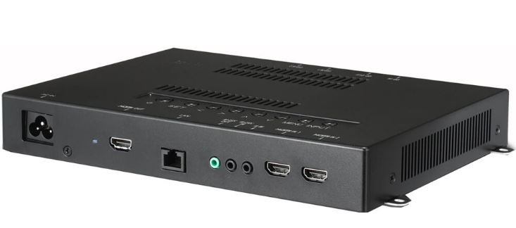
Cable Connection
- The image may vary according to the model.
Connect the RS-232C cable as in the figure.
The RS-232C protocol is used for communication between a PC and the product. It controls the power of the product, selects an input source in a PC, or controls the OSD menu.

Communication Parameter
- Board speed: 9600 BPS
- Data length: 8 bit
- Parity bit: None
- Stop bit: 1 bit
- Flow control: None
- Communication code: ASCII code
Reception/Transmission Protocol
Language
(Command: f i)
- A specific language may not be supported according to the model.
Network
(Command: s n, 80 or 81 or 82)
Transmission
- [s][n][ ][Set ID][ ][Data1][ ][Data2][ ]
- [Data3][ ][Data4][ ][Data5][Cr]
Data 1 80: Set/check the temporary IP mode (auto/manual), subnet mask, and gateway
- 81: Set/check a temporary DNS address.
- 82: Save the temporary set value, and check the current network information
- When Data 1 equals 80,
Data 2 00: Auto
- 01: Manual
- FF: Check the temporary IP mode (auto/manual), subnet mask, and gateway
- When Data 2 equals 01 (Manual),
Data 3 Manual IP address
Data 4 Subnet mask address
Data 5 Gateway address
- When Data 1 equals 81, Data 2 DNS address
- FF: Check a temporary DNS address
- When Data 1 equals 82, Data 2 80: Apply the temporarily saved IP mode (auto/manual), subnet mask, and gateway 81: Apply the temporary DNS
FF: Current network information (IP, subnet gateway,
DNS)
Setting examples:
- Auto setting: sn 01 80 00
- Manual setting: sn 01 80 01 010177223241 255255254000 010177222001 (IP:10.177.223.241, subnet: 255.255.254.0, gateway: 10.177.222.1)
- Network Reader: sn 01 80 ff
- DNS setting: sn 01 81 156147035018 (DNS: 156.147.35.18)
- Applying the set value: sn 01 82 80 (apply the saved IP mode (auto/manual), subnet mask, and gateway), sn 01 82 81 (apply the saved DSN)
Each IP address is a 12-digit decimal number.
- Acknowledgement
- [n][ ][Set ID][ ][OK/NG][Data1][Data][x]
- The feature is supported only for a wired LAN.
- It may not be supported according to the model.