Honeywell H700 Full Body Harness User Manual


Honeywell H700 Full Body Harness

FULL BODY HARNESSES AND BODY BELTS This user instruction manual covers all Miller and Miller Titan full-body harnesses, as well as body belts (excluding Line- men’s Belts). Thank you for your purchase of Honeywell Miller fall protection equipment manufactured by Honeywell Industrial Safety.
WARNING
All persons using this equipment must read, understand and follow all instructions. Failure to do so may result in serious injury or death. Do not use this equipment unless you are properly trained.
It is crucial that the authorized person/user of this equipment read and understand these instructions. Additionally, federal law requires employers to ensure that all users are trained in the proper installation, use, inspection, and maintenance of fall protection equipment. Fall protection training should be an integral part of a comprehensive safety program.
Proper use of fall arrest systems can save lives and reduce the potential of serious injuries from a fall. The user must be aware that forces experienced during the arrest of a fall or prolonged suspension may cause bodily injury. Consult a physician if there is any question about the user’s ability to use this product. Pregnant women and minor children must not use this product.
Purpose
Honeywell Industrial Safety offers a wide array of full-body harnesses for every application. While full-body harnesses may be used for positioning, travel restraint and rescue, they are the only acceptable form of body wear for fall arrest. Harness designs offer superior safety and functionality with features developed to meet key user needs, such as comfort, fit, ease-of-use, style, durability, compliance, flexibility and convenience.
WARNING
Always use a full-body harness for fall arrest. Body belts may be used for positioning and travel restraint only.
General Fall Protection Requirements
General Requirements
The user’s organization shall retain the manufacturer’s instructions and make them readily available to all users. All authorized persons/users must reference the regulations governing occupational safety, as well as applicable ANSI or CSA standards. Please refer to product labeling for information on specific OSHA regulations, and ANSI and CSA standards met by product. It is essential that the users of this type of equipment receive proper training and instruction, including detailed procedures for the safe use of such equipment in their work applicatn.io AANNSIS/I/AASSSSEP Z359.2, Minimum Requirements for a Managed Fall Protection Program, establishes guidelines and requirements for an employer’s managed fall protection program, in- cluding policies, duties, and training; fall protection procedures; eliminating and controlling fall hazards; rescue proce- dures; incident investigations; and evaluating program effectiveness.
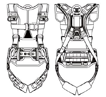
Wearing a FullgBody Harness
(Refer to “How to wear the harness” in Appendix B) Correct fit of a full-body harness is essential to proper performance. Users must be trained to select the size and maintain the fit of their full-body harness. Users must follow these instructions for proper fit and sizing, paying particular attention to ensure that buckles are connected and aligned correctly, leg straps and shoulder straps are kept snug at all times, chest straps are located in the middle chest area, and leg straps are positioned and snug to avoid contact with the genitalia should a fall occur. It is extremely important to maintain a proper fitting harness through the entire duration of a work shift Full-body harnesses which meet OSHA and current AANNSSII//AASSSSPEa nd CSA standards are intended to be used with other compo- nents of a Personal Fall Arrest System that limit maximum arrest forces to 1800 lbs (8kN) or less. Proper precautions should always be taken to remove any obstructions, debris, material, or other recognized hazards from the work area that could cause injuries or interfere with the operation of the system. Always check for obstructions below the work area to make sure potential fall path is clear. Allow adequate fall clearance below the work surface. To minimize the potential for accidental disengagement, a competent person must ensure system compatibility. All equipment must be inspected before each use according to the manufacturer’s instructions. Additionally, equipment must be inspected by a competent person, other than the user, on a regular basis, at least annually. Any product exhibiting defor- mities, unusual wear, or deterioration must be immediately discarded in such a manner as to prevent inadvertent further use.
WARNING
Any equipment subject to a fall must be removed from service. The authorized person/user shall have a rescue plan and the means at hand to implement it when using this equipment.
Equipment must not be altered in any way. Repairs must be performed only by the manufacturer, or persons or entities authorized in writing by the manufacturer. Never use fall protection equipment for purposes other than those for which it was designed. Fall protection equipment should never be used for towing or hoisting. Environmental hazards should be considered when selecting fall protection equipment. Equipment must not be exposed to chemicals, heat, flames, or other environmental conditions which may produce a harm- ful effect. Polyester should not be used in certain chemical or acidic environments. All synthetic material must be protected from slag, hot sparks, open flames, or other heat sources. The use of heat resistant materials is recommended in these ap- plications. Do not allow equipment to come in contact with anything that will damage it including, but not limited to, sharp, abrasive, rough or high-temperature surfaces, heat sources, electrical hazards, or moving machinery. Do not expose the equipment to any hazard which it is not designed to withstand. Consult the manufacturer in cases of doubt. Never remove product labels, which include important warnings and information for the authorized person/user.
Warnings and Limitations
Capacity [See TABLE 1] The allowable capacity of Miller and Miller Titan harnesses varies among the requirements of ANSI, CSA and OSHA. Based on the requirements of these fall protection standards and on Honeywell’s internal test program, the harness capacity rating for Miller and Miller Titan harnesses is as shown in TABLE 1. Users must refer to the variable harness identification label included on the harness at the time of shipping to verify the standards to which the specific harness model complies. (Refer to sample variable label in Appendix C) *Includes body weight, clothing and tools.
CSA Z259.10 does not specify a capacity range for harnesses; therefore, the manufacturer may establish the maximum capacity based on testing in accordance with CSA requirements and their internal test program. Honeywell, as the manufacturer, rates the harnesses to a maximum 420 lb (190.5 kg); however, it is ultimately the responsibility of the user and the user’s employer to determine if they elect to comply with the ANSI standards which limit capacity range to 130 310 lb (59 140 kg). Note: For compliance with OSHA 1926.502(d)(16) — If the system is used by an employee having a combined tool and body weight be- tween 310 lbs (140.6 kg) and 420 lb (190.5 kg), then the employer must appropriately modify the criteria and protocols to provide proper protection for such heavier weights, or the system will not be deemed to be in compliance with the requirements of OSHA 1926.502(d)(16).
System Compatibility
Miller full-body harnesses and body belts are designed for use with Honeywell-approved components only. Substitution or replacement with non-approved component combinations or subsystems or both may affect or interfere with the safe function of each other and endanger the compatibility within the system. This incompatibility may affect the reliability and safety of the total system.
WARNING
Always refer to the regulations and standards regarding personal fall arrest system component requirements and the instructions provided with each component being used as part of the personal fall arrest system.+
Limits of Use
Fall arrest connecting devices shall be attached to the dorsal attachment element (back D-ring) of the full-body harness unless the application allows for the use of an alternate attachment.
Anchorage Requirements
Anchorage must be capable of supporting 5,000 lbs (22.2 kN) per worker or meet OSHA 1926.502 requirements for a safety factor of two. ANSI anchorage requirements are as follows:
- For fall arrest systems, anchorages must withstand a static load of 5,000 lb (22.2 kN) for non-certified anchorag- es or two times the maximum arresting force for certified anchorages.
- For positioning systems, anchorages must withstand a static load of 3,000 lb (13.3 kN) for non-certified anchor- ages or two times the foreseeable force for certified anchorages.
- For travel restraint, anchorages must withstand a static load of 1,000 lb (4.5 kN) for non-certified anchorages or two times the foreseeable force for certified anchorages.
- When more than one personal fall arrest system is attached to an anchorage, the above anchorage strengths must be multiplied by the number of personal fall arrest systems attached to the anchorage.
Donning a Harness
- Hold harness by back D-ring. Shake harness to allow all straps to fall in place.
- If chest, waist and/or leg straps are connected, release straps by unbuckling.
- Slip straps over shoulders so D-ring is located in middle of back between shoulder blades.
- Pull leg strap between legs and connect to corresponding end. Repeat with second leg strap. Tighten leg straps so that they are snug, without obstructing normal blood circulation in the legs. Connect waist strap/belt, if present. Waist strap/ belt should be snug but not binding.
- Connect chest strap and position in midchest area 6” (152mm) to 8” (203mm) below the trachea but not below the ster- num. If adjustable, tighten chest strap to keep shoulder straps taut.
Note: If the chest strap is positioned too high, it may move upward during a fall arrest causing the user to risk strangulation. If the chest strap is positioned too low, or not connected at all, the user will be at risk of falling out of the harness during a fall. - Tighten shoulder straps until snug.
- After all webbing straps have been buckled, readjust harness fit as needed so that harness is snug but allows full range of movement. Secure excess strap in elastic loop keepers.
- Verify correct harness fit using the following checklist:
- All buckles are properly connected.
- Webbing straps are not twisted and are snug with excess webbing secured in elastic loop keepers. Back D-ring is located in middle of back between shoulder blades.
- Chest strap is positioned in mid-chest area as specified.
Helpful Hint: When not in use, Honeywell recommends hanging the harness by its back D-ring to help it keep its shape and provide the worker with a starting point when next donning the harness.
Donning a Pullover Front D Ring Harness
- If leg straps are connected, release straps by unbuckling.
- Hold harness by back D-ring and rotate so that the front D-ring is facing you.
- Grasp shoulder straps directly below the front D-ring with both hands. Place head through center of harness between the front and back D-rings.
- Spin the harness 180 degrees and adjust harness so that the shoulder straps run vertically over the chest, the front D-ring is positioned in the mid-chest area, and the back D-ring is located in the middle of the back between the shoulder blades.
- Pull leg strap between legs and connect to corresponding end. Repeat with second leg strap. Tighten leg straps so that they are snug without obstructing normal blood circulation in the legs.
- Using the friction buckles, adjust shoulder straps until snug.
- Readjust harness fit as needed so that harness is snug but allows full range of movement. Secure excess strap in elastic loop keepers.
Donning a Ms. Miller Harness (570 / E570)
- Hold harness by back D-ring. Shake harness to allow all straps to fall in place.
- If chest and leg straps are connected, release straps by unbuckling.
- Holding harness by the shoulder straps, step through the waist strap and slip shoulder straps over shoulders so that the back D-ring is located in the middle of the back between shoulder blades.
- Pull leg strap between legs and connect to corresponding end. Repeat with second leg strap. Tighten leg straps so that they are snug without obstructing normal blood circulation in the legs.
- Tighten waist strap. Waist strap should be snug, but not binding.
- Connect chest strap and position in midchest area 6” (152mm) to 8” (203mm) below the trachea but not below the sternum. Tighten to keep shoulder straps taut.
- After all webbing straps have been buckled, readjust harness fit as needed so that the harness is snug but allows full range of movement. Secure excess strap in elastic loop keepers.
Using a FullgBody Harness
Use of Attachment Elements (D Rings/Web Loops) [See Table 2]
The dorsal attachment element or back Dring/ web loop shall be used as the primary fall arrest attachment, unless the ap- plication allows for the use of an alternate attachment. The dorsal attachment may also be used for travel restraint or rescue.
When supported by the dorsal attachment during a fall, the design of the full-body harness shall distribute the load through the shoulder and leg straps, supporting the user, and through the thighs. Supporting the user, post fall, by the dorsal attachment will result in an upright body position with a slight lean to the front with some slight pressure to the lower chest. Considerations should be made when choosing a sliding or fixed dorsal attachment design. Sliding dorsal attachments are generally easier to adjust to different user sizes than a fixed design, and a allow a more vertical rest position post fall, but can increase full-body harness stretch.
CAUTION: Due to the nature of soft loop connections, it is recommended that only soft loops and carabiners be used to connect to soft loop attachments. Connecting snap hooks to soft loops is not a preferred connection. However, if a snap hook is used to connect to a soft loop, the snap hook must be ANSI compliant with a gate strength of at least 3,600 lb (16 kN). (Current CSA standards do not allow the use of snap hooks with soft loops.)
Sternal Attachment Element – Chest Area Front D Ring
The sternal attachment may be used as an alternative fall arrest attachment in applications where the dorsal attachment is determined to be inappropriate by a competent person and where there is no chance to fall in a direction other than feet first. Free fall shall be limited to 2 ft. (0.6m). Accepted practical uses for a sternal attachment include, but are not limited to, ladder climbing with a guided type fall arrester, ladder climbing with an overhead self-retracting lifeline for fall arrest, work positioning, and rope access. The sternal attach- ment may also be used for travel restraint or rescue.
*This table provides a quick reference guide for approved uses of harness attachment elements; however, all information provided for each different attachment element must be read, understood and followed to ensure proper use and safety.
When supported by the sternal attachment during a fall, the design of the full-body harness shall direct load through the shoulder straps, supporting the user, and around the leg straps and thighs. Supporting the user, post fall, by the sternal attachment will likely result in a sitting or cradled body position with weight concentrated on the thighs, buttocks and lower back. Supporting the user during work positioning by this sternal attachment will result in an almost upright body position.
If the sternal attachment is used for fall arrest, the competent person evaluating the application should take measures to ensure that a fall can only occur feet first. This may include limiting the allowable free fall distance. It may be possible for a sternal attachment incorporated into an adjustable style chest strap to cause the chest strap to slide up and pos- sibly choke the user during a fall, extraction, suspension, etc. The competent person should consider full-body harness models with a fixed sternal attachment for these applications.
WARNING
Always ensure that the connecting device snap hook (or other connector) is compatible with the harness D-ring, is properly engaged, and is closed and locked.
Shoulder Attachment – Elements and Shoulder D Rings
The shoulder attachment elements shall be used as a pair and are an acceptable attachment for rescue and entry/ retrieval. It is recommended that the shoulder attachment elements be used in conjunction with a yoke which incorpo- rates a spreader element to keep the full-body harness shoulder straps separate.
Rear Waist Attachment – Element
The rear-waist attachment element shall be used solely for travel restraint. The rear-waist attachment shall only be subjected to minimal loading through the waist of the user and shall never be used to support the full weight of the user.
WARNING
Do not use the rear-waist attachment element for any purpose other than travel restraint.
Proper and Compatible Connection to Attachment Elements
WARNING
Always ensure that the connecting device snap hook (or other connector) is compatible with the harness D-ring, is properly engaged, and is closed and locked.
IMPORTANT NOTE
An improper or incomplete engagement is possible when the inside diameter of the D-ring is very close to the width of the snap hook. As a result, when attempting to engage the snap hook of a connecting device with a D-ring at the back of a harness, the user experiences a feeling of proper engagement, while in fact, the snap hook sits only inside the D-ring. This improper or incomplete engagement is unsafe and is likely to come apart during a fall arrest.
Use of Other Harness Features
Harnesses are equipped with pull-free lanyard rings, also known as lanyard parking attachments. When a connecting device or lanyard is attached to a harness D-ring, but a lanyard leg is not currently in use, the unused lanyard leg shall be stored by connecting it to the lanyard parking attachment. The lanyard parking attachment is generally located in the sternal area to help reduce tripping and entanglement hazards.
CAUTION: Do not attach an unused lanyard leg to a work positioning element or any other structural element on the full- body harness unless deemed acceptable by the competent person and manufacturer of the harness and lanyard. This is especially important when using some types of “Y” style or double-leg lanyards as some load may be transmitted to the user through the unused leg if it is not able to release from the harness.
Elastic Keepers and Web Finials
All full-body harnesses shall include keepers or other components which serve to control loose ends of webbing straps. Miller harnesses are equipped with elastic keepers to store the loose or excess webbing straps. Some harnesses are also equipped with web finials on the ends of each webbing strap to further help secure webbing straps in place. Simply hook the clip of the web finial to the underlying harness strap.
CAUTION: Do not allow webbing straps to hang freely as loose ends of straps can get caught in machinery or cause acci- dental disengagement of an adjuster.
D Ring Extension
Some specialty harnesses may be equipped with a dorsal D-ring extension. This dorsal D-ring extension may be used as the fall arrest attachment element in place of the dorsal D-ring. When not in use, the D-ring extension shall be stored in the designated elastic keeper.
CAUTION: Do not use dorsal D-ring and dorsal D-ring extension simultaneously for fall arrest; only one fall arrest at- tachment element may be used at a given time. Always account for the additional length of the D-ring extension when calculating fall clearance (refer to 6.0).
Using a Body Belt
A body belt shall be used for positioning or travel restraint only. Body belts may be used in conjunction with a full-body harness; however, the fall arrest attachment elements designated on the harness must be used for fall protection.
WARNING
Do not use the rear-waist attachment element for any purpose other than travel restraint.
Calculating Fall Clearance Distance
It is essential to understand how to calculate the fall clearance distance required for each work application to avoid contact with a lower level. The basic calculations shown in this section and the related diagrams in Appendix A may be used to determine Required Fall Clearance when using a shock-absorbing lanyard or self-retracting lifeline in an overhead application. As many addi- tional variables or factors can affect fall clearance, it is imperative that the user also refer to the instructions provided with the connecting device for more comprehensive information. For a more automated approach to calculating Required Fall Clearance, access the Miller Fall Clearance Calculator online:
Fall Clearance Calculation Guidelines:
- Full-body harness stretch is limited to 18 in. (457.2mm) or less. Full-body harness stretch, the amount the full-body harness component of a personal fall arrest system will stretch and deform during a fall, can contribute to the overall elongation of the system in stopping a fall. It is important to include the increase in fall distance created by full-body harness stretch, as well as the full-body harness connector length, the settling of the user’s body in the full-body harness, and all other contributing factors when calculating total clearance required for a particular fall arrest system. Honeywell Safety Products recommends and includes a 3 ft. (0.9m) safety/stretch factor in its calculations.
- When a D-ring extension is used, add the length of the extension to the fall clearance calculation.
- Shock absorbers will elongate when subjected to fall arrest forces. Refer to the labels provided with the connecting de- vice to determine the maximum elongation distance, and be sure to use the maximum elongation distance to calculate required fall clearance.
NOTE: The shock-absorbing lanyard calculation determines required fall clearance from the connection point of the lanyard (to the anchorage connector or anchorage) to the next lower level or obstruction below the work surface. The self-retracting lifeline calculation determines required fall clearance from the work level to the next lower level or obstruction.
SHOCK ABSORBING LANYARD FALL CLEARANCE CALCULATION [Calculation taken from connection point of lanyard to anchorage connector or anchorage] Length of Lanyard (LL) SELF RETRACTING LIFELINE FALL CLEARANCE CALCULATION (see Fig. 17b in Appendix A) [Calculation taken from work level] Maximum Arrest Distance (MAD)
- Max. Elongation/Deceleration Distance (MED)
- Height to Worker’s Back D Ring (H)
- 3 ft. (0.9m) Safety/Stretch Factor (SF)
- Required Fall Clearance (RFC)
- [Non Standing Work Position Factor (NSF)]*
- [Swing Fall Factor (SFF)]*
- 3 ft. (0.9m) Safety/Stretch Factor (SF)
- Required Fall Clearance (RFC)
Inspection and Maintenance
Users of personal fall arrest systems shall, at a minimum, comply with all manufacturer instructions regarding the in- spection, maintenance and storage of the equipment. (See AANNSSII//AASSSSPE Z359.2, Minimum Requirements for a Managed Fall Protection Program regarding user inspection, maintenance and storage of equipment.)
Harness and Body Belt Inspection
Honeywell Safety Products’ inspection requirements incorporate the criteria established by current safety standards. The inspection criteria for the equipment shall be set by the user’s organization, such that it equals or exceeds the criteria re- quired by the manufacturer and the standards with which the organziation elects to comply. Equipment shall be thoroughly inspected by the user before each use, and additionally, by a competent person, other than the user, at regular intervals of no more than one year for: Absence or illegibility of markings/labels.Refer to Appendix B: Product Labels for details on accessing harness labels. Absence of any elements affecting the equipment form, fit or function. To inspect, grasp webbing with hands 6 8 inches (152 203mm) apart and bend webbing in an inverted “U”. The result- ing surface tension makes damaged fibers or cuts easier to detect. Follow this procedure the entire length of webbing, inspecting both sides of each strap. Evidence of defects in or damage to hardware elements including cracks, breaks, rough or sharp edges, deforma- tion, corrosion, chemical attack, excessive heating, alteration, and excessive wear. Additionally, perform the following hardware checks:
D Ring: D-ring should pivot freely.
Tongue Buckles/Grommets: Buckle tongues should be free of distortion in shape and motion. They should overlap the buckle frame and move freely back and forth in their socket. Roller should turn freely on frame. Inspect for loose, distorted or broken grommets. Webbing should not have additional punched holes.
Cam Buckles: Make sure the cam mechanism is free of debris and engages the webbing properly.
Friction and Slotted Mating Buckles: The outer bars and center bars must be straight. Pay special attention to corners and attachment points at the center bar.
Quick Connect Buckles: Make sure dual-tab release mechanism is free of debris and engages properly. Double-check the buckle locking mechanism by tugging on both halves of the buckle to make sure it is firmly connected and will not disengage without the use of the release levers.
Lifecycle
The estimated lifespan of the products or harness is 5 years. However, the following factors may reduce the performance of the product and its lifespan: incorrect storage, improper use, fall arrest, deformation, contact with chemical products (alkali and acid), and exposure to sources of heat >60°C (cf. 9).
Cleaning and maintenance
The harness should be cleaned with with wet rag to remove dirtyness and dust. Never use acid, solvents or any solvent-based product, Leave to dry in a well-ventilated area, away from sources of heat. Store the harness away from humidity and ultraviolet light, Avoid storage with direct sun exposure Avoid any atmosphere that is corrosive or excessively hot or refrigerated.
Transport
Transportation, storage and packaging
During transport, check that your PPE is stored well away from any source of heat, damp, corrosive atmosphere, ultraviolet rays, etc. This harness is sold in rot proof and waterproof plastic packaging, with its instructions for use.