Makita DBO180 Cordless Random Orbit Sander Instruction Manual


Cordless Random Orbit Sander

Instruction Manual
DBO140
DBO180


(Original instructions)
Explanation of general view
| 1 Red indicator 2 Button 3 Battery cartridge 4 Star marking 5 Stop button 6 Start/speed adjusting button |
7Pad 8 Abrasive disc 9 Dustbag 10 Dust nozzle 11 Holding tab 12 Dust box |
13 Latch 14 Skirt 15 Screw 16 Sponge pad 17 Felt pad 18 Wool pad |
SPECIFICATIONS
| Model | DB0140 | DB0180 | |
| Paper size | 125 mm | ||
| Orbits per minute (min-1) | Low speed | 7,000 | |
| Middle speed | 9,500 | ||
| High speed | 11,000 | ||
| Dimensions | 175 mm x 123 mm x 153 mm | ||
| Net weight | 1.6 kg | 1.7 kg | |
| Rated voltage | D.C. 14.4 V | D.C. 18 V | |
- Due to our continuing program of research and development, the specifications herein are subject to change without notice.
- Specifications and battery cartridges may differ from country to country.
- Weight, with battery cartridge, according to EPTA-Procedure 01/2003
ENE052-1
Intended use
The tool is intended for the sanding of large surfaces of wood, plastic, and metal materials as well as painted surfaces.
GEA010-1
General Power Tool Safety Warnings
Save all warnings and instructions for future reference. GEB021-4

SANDER SAFETY WARNINGS
- Always use safety glasses or goggles. Ordinary eyes or sunglasses are NOT safety glasses.
- Hold the tool firmly.
- Do not leave the tool running. Operate the tool only when hand-held.
- This tool has not been waterproofed, so do not use water on the workpiece surface.
- Ventilate your work area adequately when you perform sanding operations.
- Some material contains chemicals that may be toxic. Take caution to prevent dust inhalation and skin contact. Follow material supplier safety data.
- The use of this tool to sand some products, paints, and wood could expose users to dust containing hazardous substances. Use appropriate respiratory protection.
- Be sure that there are no cracks or breakage on the pad before use. Cracks or breakage may cause a personal injury.
SAVE THESE INSTRUCTIONS.
DO NOT let comfort or familiarity with the product (gained from repeated use) replace strict adherence to safety rules for the subject product. MISUSE or failure to follow the safety rules stated in this instruction manual may cause serious personal injury. ENC007-7
IMPORTANT SAFETY INSTRUCTIONS
FOR BATTERY CARTRIDGE
- Before using the battery cartridge, read all instructions and cautionary markings on (1) battery charger, (2) battery, and (3) product using the battery.
- Do not disassemble the battery cartridge.
- If the operating time has become excessively shorter, stop operating immediately. It may result in a risk of overheating, possible burns, and even an explosion.
- If electrolyte gets into your eyes, rinse them out with clear water and seek medical attention right away. It may result in loss of your eyesight.
- Do not short the battery cartridge:
(1) Do not touch the terminals with any conductive material.
(2) Avoid storing battery cartridges in a container with other metal objects such as nails, coins, etc.
(3) Do not expose the battery cartridge to water or rain.
A battery short can cause a large current flow, overheating, possible burns, and even a breakdown. - Do not store the tool and battery cartridge in locations where the temperature may reach or exceed 50°C (122°F).
- Do not incinerate the battery cartridge even if it is severely damaged or is completely worn out.
The battery cartridge can explode in a fire. - Be careful not to drop or strike the battery.
- Do not use a damaged battery.
SAVE THESE INSTRUCTIONS.
Tips for maintaining maximum battery life
- Charge the battery cartridge before completely discharged. Always stop tool operation and charge the battery cartridge when you notice less tool power.
- Never recharge a fully charged battery cartridge. Overcharging shortens the battery service life.
- Charge the battery cartridge at room temperature at 10°C – 40°C (50°F – 104°F). Let a hot battery cartridge cool down before charging it.
- Charge the battery cartridge once every six months if you do not use it for a long period of time.
FUNCTIONAL DESCRIPTION
- Always be sure that the tool is switched off and the battery cartridge is removed before adjusting or checking the function of the tool.
Installing or removing the battery cartridge (Fig. 1) - Always switch off the tool before installing or removing the battery cartridge.
- Hold the tool and the battery cartridge firmly when installing or removing the battery cartridge. Failure to hold the tool and the battery cartridge firmly may cause them to slip off your hands and result in damage to the tool and battery cartridge and a personal injury.
To remove the battery cartridge, slide it from the tool while sliding the button on the front of the cartridge.
To install the battery cartridge, align the tongue on the battery cartridge with the groove in the housing and slip it into place. Insert it all the way until it locks in place with a little click. If you can see the red indicator on the upper side of the button, it is not locked completely.
- Always install the battery cartridge fully until the red indicator cannot be seen. If not, it may accidentally fall out of the tool, causing injury to you or someone around you.
- Do not install the battery cartridge forcibly. If the cartridge does not slide in easily, it is not being inserted correctly.
Battery protection system (Lithium-ion battery with star marking) (Fig. 2)
Lithium-ion batteries with a star marking are equipped with a protection system. This system automatically cuts off power to the tool to extend battery life.
The tool will automatically stop during operation if the tool and/or battery are placed under one of the following conditions:
- Overloaded:
The tool is operated in a manner that causes it to draw an abnormally high current.
In this situation, stop the application that caused the tool to become overloaded. Then press the start/speed adjusting button again to restart.
If the tool does not start, the battery is overheated. In this situation, let the battery cool before pressing the start/speed adjusting button. - Low battery voltage:
The remaining battery capacity is too low and the tool will not operate. In this situation, remove and recharge the battery.
Switch action and speed adjusting button (Fig. 3)
To start the tool, press the start/speed adjusting button. The tool starts with high-speed mode. Each time you press the start/speed adjusting button, the speed mode changes in an order of hi-speed, middle speed, and low speed.
To stop the tool, press the stop button.
Refer to the table for the relationship between the speed mode and the kind of work.
| Speed mode | Number of rotations | Usage |
| High | 11,000 | Regular sanding |
| Middle | 9,500 | Finish sanding |
| Low | 7,000 | Polishing |
012897
NOTE:
- The table shows standard applications. They may differ under certain conditions.
ASSEMBLY
- Always be sure that the tool is switched off and the battery cartridge is removed before carrying out any work on the tool.
Installing abrasive disc (Fig. 4)
To install the abrasive disc, first, remove all dirt or foreign matter from the pad. Then attach the abrasive disc to the pad. Be careful to align the holes in the abrasive disc with those in the pad.
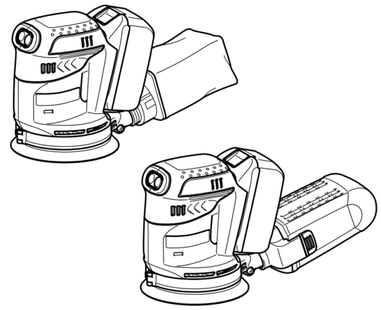
Installing dust bag (optional accessory) (Fig. 5)
Install the dust bag on the tool with its mouth directing downwards.
Emptying dust bag (Fig. 6 & 7)
When the dust bag is about half full, switch off the tool, and remove the dust bag from the tool. Then remove the dust nozzle from the dust bag after unlocking the dust nozzle by turning it slightly counterclockwise. Empty the dust bag by tapping it lightly.
After emptying the dust bag, install the dust nozzle on the dust bag. Turn the dust nozzle slightly clockwise to lock it in place. Then install the dust bag on the tool as described in “Installing dust bag”.
Installing a paper filter bag (optional accessory) (Fig. 8 & 9)
Make sure that the logo on the cardboard lip and the logo on the dust box is on the same side, then install the paper filter bag by fitting the cardboard lip in the groove of each holding tab.
Make sure that the logo on the cardboard lip and the logo on the dust nozzle is on the same side, then install the dust nozzle on the dust box.
Removing dust box and paper filter bag (Fig. 10 & 11)
Remove the dust nozzle by pushing the two latches.
Remove the paper filter bag first by pinching the logo side of its cardboard lip, then by pulling the cardboard lip downwards to move it out of the holding tab of the dust box.
Removing and reinstalling the skirt (Fig. 12, 13 & 14)
- Do not use the tool without the skirt. Otherwise, dust is scattered all over. You can choose one of the 12 directions of the skirt in accordance with your purpose. To remove the skirt, remove the screw and remove the skirt by slightly opening it on both sides. To reinstall the skirt, install it by slightly opening it on both sides. And fasten the screw.
- Do not set the skirt other than the designated angle. Otherwise, the tool may be damaged.
OPERATION
- Never switch on the tool when it is in contact with the workpiece, it may cause an injury to the operator.
Sanding operation (Fig. 15)
- Never run the tool without the abrasive disc. You may seriously damage the pad.
- Never force the tool. Excessive pressure may decrease the sanding efficiency, damage the abrasive disc or shorten tool life.
- Using the tool with the pad edge contacting the workpiece may damage the pad.
Hold the tool firmly. Turn the tool on and wait until it attains full speed. Then gently place the tool on the workpiece surface. Keep the pad flush with the workpiece and apply slight pressure on the tool.
- The sanding pad rotates clockwise during the loaded operation, but it may rotate counterclockwise during the no-load operation.
Polishing operation (optional)
- Use only a Makita genuine sponge pad, felt pad, or wool pad (optional accessories).
- Always operate the tool at low speed to prevent work surfaces from heating abnormally.
- Never force the tool. Excessive pressure may decrease the polishing efficiency and cause motor overload, resulting in tool malfunction.
- Applying wax (Fig. 16)
Use an optional sponge pad. Apply wax to the sponge pad or work surface. Run the tool at a low speed to smooth out the wax.
NOTE:
• First, wax a not conspicuous portion of the work surface to make sure that the tool will not scratch the sur- face or result in uneven waxing.
• The tool starts with high-speed mode. Be careful when you start the tool. The wax may bespatter. It is recommended that you spread wax with the tool stopped before starting up the tool. Change the speed mode to low immediately after you start the tool.
• Always run the tool at low speed. Running it at high speed may cause the wax to spatter. - Removing wax (Fig. 17)
Use an optional felt pad. Run the tool at low speed to remove wax. - Polishing (Fig. 18)
Use an optional wool pad. Run the tool at low speed and apply the wool pad gently to the work surface.
MAINTENANCE
- Always be sure that the tool is switched off and the battery cartridge is removed before attempting to perform inspection or maintenance.
- Never use gasoline, benzene, thinner, alcohol, or the like. Discoloration, deformation, or cracks may result. To maintain product SAFETY and RELIABILITY, repairs, carbon brush inspection, and replacement, any other maintenance or adjustment should be performed by Makita Authorized Service Centers, always using Makita replacement parts.
OPTIONAL ACCESSORIES
- These accessories or attachments are recommended for use with your Makita tool specified in this manual. The use of any other accessories or attachments might present a risk of injury to persons. Only use accessory or attachment for its stated purpose. If you need any assistance with more details regarding For these accessories, ask your local Makita Service Center.
- Hook-and-loop type abrasive discs (with pre-punched holes)
- Hook-and-loop type sponge pad
- Hook-and-loop type felt pad
- Hook-and-loop type wool pad
- Makita genuine battery and charger
- Dust box
- Paper filter bag
- Dust bag
NOTE:
- Some items in the list may be included in the tool package as standard accessories. They may differ from country to country.
ENG905-1
Noise
The typical A-weighted noise level is determined according to EN60745:
Model DBO140
Sound pressure level (LpA): 78 dB (A)
Uncertainty (K): 3 dB (A)
The noise level under working may exceed 80 dB (A).
Model DBO180
Sound pressure level (LpA): 77 dB (A)
Uncertainty (K): 3 dB (A)
The noise level under working may exceed 80 dB (A).
Wear ear protection
ENG900-1
Vibration
The vibration total value (tri-axial vector sum) determined according to EN60745:
Model DBO140
Work mode: sanding metal plate Vibration emission (ah): 2.5 m/s2 or less
Uncertainty (K): 1.5 m/s2
Model DBO180
Work mode: sanding metal plate
Vibration emission (ah): 2.5 m/s² or less
Uncertainty (K): 1.5 m/s²
ENG901-1
- The declared vibration emission value has been measured in accordance with the standard test method and may be used for comparing one tool with another.
- The declared vibration emission value may also be used in a preliminary assessment of exposure.
- WARNING:
- The vibration emission during actual use of the power tool can differ from the declared emission value depending on the ways in which the tool is used.
- Be sure to identify safety measures to protect the operator that is based on an estimation of exposure in the actual conditions of use (taking account of all parts of the operating cycle such as the times when the tool is switched off and when it is running idle in addition to the trigger time).
For European countries only
EC Declaration of Conformity
We Makita Corporation as the responsible manufacturer declares that the following Makita machine(s):
Designation of Machine: Cordless Random Orbit Sander Model No./ Type: DBO140, DBO180 are of series production and
Conforms to the following European Directives:
2006/42/EC
And are manufactured in accordance with the following standards or standardized documents:
EN60745
The technical documentation is kept by our authorized representative in Europe who is:
Makita International Europe Ltd.
Michigan Drive, Tongwell,
Milton Keynes, Bucks MK15 8JD, England
14.9.2011
Tomoyasu Kato
Director
Makita Corporation
3-11-8, Sumiyoshi-cho,
Anjo, Aichi, 446-8502, JAPAN

Makita Corporation
Anjo, Aichi, Japan
www.makita.com